EP1126196B1 - Housing for a manual automotive gearbox - Google Patents
Housing for a manual automotive gearbox Download PDFInfo
- Publication number
- EP1126196B1 EP1126196B1 EP01400302A EP01400302A EP1126196B1 EP 1126196 B1 EP1126196 B1 EP 1126196B1 EP 01400302 A EP01400302 A EP 01400302A EP 01400302 A EP01400302 A EP 01400302A EP 1126196 B1 EP1126196 B1 EP 1126196B1
- Authority
- EP
- European Patent Office
- Prior art keywords
- housing
- sealing cover
- transmission gear
- housing part
- supporting shaft
- Prior art date
- Legal status (The legal status is an assumption and is not a legal conclusion. Google has not performed a legal analysis and makes no representation as to the accuracy of the status listed.)
- Expired - Lifetime
Links
Images

Classifications
-
- F—MECHANICAL ENGINEERING; LIGHTING; HEATING; WEAPONS; BLASTING
- F16—ENGINEERING ELEMENTS AND UNITS; GENERAL MEASURES FOR PRODUCING AND MAINTAINING EFFECTIVE FUNCTIONING OF MACHINES OR INSTALLATIONS; THERMAL INSULATION IN GENERAL
- F16H—GEARING
- F16H57/00—General details of gearing
- F16H57/02—Gearboxes; Mounting gearing therein
- F16H57/031—Gearboxes; Mounting gearing therein characterised by covers or lids for gearboxes
-
- F—MECHANICAL ENGINEERING; LIGHTING; HEATING; WEAPONS; BLASTING
- F16—ENGINEERING ELEMENTS AND UNITS; GENERAL MEASURES FOR PRODUCING AND MAINTAINING EFFECTIVE FUNCTIONING OF MACHINES OR INSTALLATIONS; THERMAL INSULATION IN GENERAL
- F16H—GEARING
- F16H57/00—General details of gearing
- F16H57/02—Gearboxes; Mounting gearing therein
- F16H57/023—Mounting or installation of gears or shafts in the gearboxes, e.g. methods or means for assembly
-
- F—MECHANICAL ENGINEERING; LIGHTING; HEATING; WEAPONS; BLASTING
- F16—ENGINEERING ELEMENTS AND UNITS; GENERAL MEASURES FOR PRODUCING AND MAINTAINING EFFECTIVE FUNCTIONING OF MACHINES OR INSTALLATIONS; THERMAL INSULATION IN GENERAL
- F16H—GEARING
- F16H57/00—General details of gearing
- F16H57/02—Gearboxes; Mounting gearing therein
- F16H2057/02039—Gearboxes for particular applications
- F16H2057/02043—Gearboxes for particular applications for vehicle transmissions
-
- F—MECHANICAL ENGINEERING; LIGHTING; HEATING; WEAPONS; BLASTING
- F16—ENGINEERING ELEMENTS AND UNITS; GENERAL MEASURES FOR PRODUCING AND MAINTAINING EFFECTIVE FUNCTIONING OF MACHINES OR INSTALLATIONS; THERMAL INSULATION IN GENERAL
- F16H—GEARING
- F16H57/00—General details of gearing
- F16H57/02—Gearboxes; Mounting gearing therein
- F16H2057/02086—Measures for reducing size of gearbox, e.g. for creating a more compact transmission casing
-
- F—MECHANICAL ENGINEERING; LIGHTING; HEATING; WEAPONS; BLASTING
- F16—ENGINEERING ELEMENTS AND UNITS; GENERAL MEASURES FOR PRODUCING AND MAINTAINING EFFECTIVE FUNCTIONING OF MACHINES OR INSTALLATIONS; THERMAL INSULATION IN GENERAL
- F16H—GEARING
- F16H57/00—General details of gearing
- F16H57/02—Gearboxes; Mounting gearing therein
- F16H2057/02091—Measures for reducing weight of gearbox
-
- F—MECHANICAL ENGINEERING; LIGHTING; HEATING; WEAPONS; BLASTING
- F16—ENGINEERING ELEMENTS AND UNITS; GENERAL MEASURES FOR PRODUCING AND MAINTAINING EFFECTIVE FUNCTIONING OF MACHINES OR INSTALLATIONS; THERMAL INSULATION IN GENERAL
- F16H—GEARING
- F16H57/00—General details of gearing
- F16H57/02—Gearboxes; Mounting gearing therein
- F16H57/023—Mounting or installation of gears or shafts in the gearboxes, e.g. methods or means for assembly
- F16H2057/0235—Mounting or installation of gears or shafts in the gearboxes, e.g. methods or means for assembly specially adapted to allow easy accessibility and repair
Definitions
- the present invention relates to a gearbox housing manual gearbox for motor vehicle according to the preamble of claim 1 and as known of document FR 2 492 033.
- reverse gear In the current architecture of a box of manual gears, reverse gear is located at the bottom of the gearbox housing and the presence of the pinion reverse gear often requires having a large housing at the end to be able to wrap this intermediate gear.
- the present invention proposes to remedy the above drawback.
- the gearbox housing manual gearbox for motor vehicle including a housing part of the intermediate gear rear, is characterized in that it comprises a closing cover of the housing housing part of the intermediate pinion which is removably attached to this part by a clip whose ends engage respectively in two blind holes in the part of the casing.
- the closing cover is fixed to the part of the casing by means of a gasket in support on the peripheral edge of the housing opening of the intermediate pinion which projects in part at through this opening in the closing cover.
- the closing cover is of general shape rectangular and its curved closing wall towards the outside and the fastening clip is a rod U-shaped metal with elongated base resting on the curved outer face of the cover wall longitudinally to it and whose branches have their free ends curved substantially at an angle right engaging the two blind holes in the part of the casing.
- the curved outer face of the wall of the cover closure includes a notch for receiving the central portion of the elongated base of the stem metallic.
- the intermediate gear is mounted idly on an axis of support fixed in the part of the housing, housed at its ends respectively in two bores of the part of the casing and retained therein by a plug of closing of one of the two bores and accessible from the exterior to allow the assembly and disassembly of the idler support axis.
- the intermediate gear is mounted on the axis of support via a plain bearing and a needle sleeve and friction washers are mounted on the support axis on either side of the pinion intermediate.
- the reference 1 designates a manual gearbox housing for vehicle automobile and only the housing part of the pinion reverse gear 2 and located at the bottom of the housing 1, is shown.
- Intermediate pinion 2 is meshed with a reverse gear 3 and the shaft primary AP as shown in Figure 5 and is mounted at rotation on a support axis 4 fixed in the part of the housing serving as an intermediate pinion housing 2.
- an external cover is provided. 5 for closing the part of the housing casing intermediate gear 2 and which is removably attached to the part by an elastic clip 6, the ends of which engage respectively in two opposite blind holes and aligned 7 of the part of the casing 1a.
- the closure cover 5 is generally rectangular in shape and has a wall of closure 5a which is curved outwards, in particular in its central part.
- the fastening clip 6 is consisting of a U-shaped metal rod based 6a elongated and resting on the curved external face of the central part of the wall 5a of the cover 5 in extending longitudinally to this wall. Branches 6b of the U-shaped rod have their free ends 6c curved substantially at right angles engaging in the two blind holes 7.
- the curved external face of the central part of the wall 5a of the cover 5 comprises a notch 5b extending longitudinally at cover 5 and intended to receive the central portion of the elongated base 6a of the rod 6 in the shape of a U.
- the cover 5 has a peripheral rim 5c of form fitting into a conjugate form peripheral of a seal 8 made of a material to rubber base of generally rectangular shape and coming to rest on the peripheral edge 1c delimiting the opening of the pinion housing intermediate 2 which projects in part through this opening, a rectangular opening 8a of the joint 8 and in the internal hollow part of the cover 5.
- the seal is pressed between the cover 5 and the peripheral edge 1c of the housing part the by the elastic holding force exerted by the clip fixing 6.
- the intermediate gear 2 is mounted idly on the axis 4 which has its two ends fixed respectively in two coaxial bores 9 machined in the part of the casing la, one end of the axis 4 being in abutment at the bottom of the corresponding bore 9 while the other end of this axis is retained in the other bore 9 by a plug 10 fixed at the entrance to bore 9 and accessible from the exterior to allow possible disassembly of the axis support 4.
- the intermediate pinion 2 is rotatably mounted on the support axis 4 by means of a plain bearing.
- tubular 11 or a needle socket and two friction washers 13 are mounted on the axis 4 on the and other of the intermediate pinion 2.
- a needle stopper as shown in Figure 1 in the right part thereof.
- the arrangement described above of the invention allows to get a less gearbox housing bulky, therefore less mass, mounting and easy removal of the intermediate reverse gear and a simple demoulding of the gearbox housing, while remaining extremely simple in design.
Abstract
Description
La présente invention concerne un carter de boíte
de vitesses manuelle pour véhicule automobile
selon le préambule de la revendication 1 et comme connu
du document FR 2 492 033.The present invention relates to a gearbox housing
manual gearbox for motor vehicle
according to the preamble of claim 1 and as known
of
Dans l'architecture actuelle d'une boíte de vitesses manuelle, la marche arrière est située au fond du carter de boíte de vitesses et la présence du pignon intermédiaire de marche arrière oblige souvent à avoir un carter volumineux en extrémité pour pouvoir envelopper ce pignon intermédiaire.In the current architecture of a box of manual gears, reverse gear is located at the bottom of the gearbox housing and the presence of the pinion reverse gear often requires having a large housing at the end to be able to wrap this intermediate gear.
La présente invention propose de remédier à l'inconvénient ci-dessus.The present invention proposes to remedy the above drawback.
A cet effet, selon l'invention, le carter de boíte de vitesses manuelle pour véhicule automobile comprenant une partie de logement du pignon intermédiaire de marche arrière, est caractérisé en ce qu'il comprend un couvercle de fermeture de la partie du carter de logement du pignon intermédiaire qui est fixé amoviblement à cette partie par une agrafe dont les extrémités s'engagent respectivement dans deux trous borgnes de la partie du carter.To this end, according to the invention, the gearbox housing manual gearbox for motor vehicle including a housing part of the intermediate gear rear, is characterized in that it comprises a closing cover of the housing housing part of the intermediate pinion which is removably attached to this part by a clip whose ends engage respectively in two blind holes in the part of the casing.
Le couvercle de fermeture est fixé à la partie du carter par l'intermédiaire d'un joint d'étanchéité en appui sur le bord périphérique de l'ouverture du logement du pignon intermédiaire qui fait en partie saillie à travers cette ouverture dans le couvercle.de fermeture.The closing cover is fixed to the part of the casing by means of a gasket in support on the peripheral edge of the housing opening of the intermediate pinion which projects in part at through this opening in the closing cover.
Le couvercle de fermeture est de forme générale rectangulaire et a sa paroi de fermeture bombée vers l'extérieur et l'agrafe de fixation est une tige métallique en forme de U à base allongée en appui sur la face externe bombée de la paroi du couvercle longitudinalement à celle-ci et dont les branches ont leurs extrémités libres recourbées sensiblement à angle droit s'engageant dans les deux trous borgnes de la partie du carter.The closing cover is of general shape rectangular and its curved closing wall towards the outside and the fastening clip is a rod U-shaped metal with elongated base resting on the curved outer face of the cover wall longitudinally to it and whose branches have their free ends curved substantially at an angle right engaging the two blind holes in the part of the casing.
La face externe bombée de la paroi du couvercle de fermeture comporte une échancrure de réception de la portion centrale de la base allongée de la tige métallique. The curved outer face of the wall of the cover closure includes a notch for receiving the central portion of the elongated base of the stem metallic.
Le pignon intermédiaire est monté fou sur un axe de support fixé dans la partie du carter, logé à ses extrémités respectivement dans deux alésages de la partie du carter et retenu dans ceux-ci par un bouchon de fermeture de l'un des deux alésages et accessible de l'extérieur pour permettre le montage et le démontage de l'axe de support du pignon fou.The intermediate gear is mounted idly on an axis of support fixed in the part of the housing, housed at its ends respectively in two bores of the part of the casing and retained therein by a plug of closing of one of the two bores and accessible from the exterior to allow the assembly and disassembly of the idler support axis.
Le pignon intermédiaire est monté sur l'axe de support par l'intermédiaire d'un palier lisse et d'une douille à aiguilles et des rondelles de friction sont montées sur l'axe de support de part et d'autre du pignon intermédiaire.The intermediate gear is mounted on the axis of support via a plain bearing and a needle sleeve and friction washers are mounted on the support axis on either side of the pinion intermediate.
L'invention sera mieux comprise et d'autres buts, caractéristiques, détails et avantages de celle-ci apparaítront plus clairement dans la description explicative qui va suivre faite en référence aux dessins annexés donnés uniquement à titre d'exemple illustrant un mode de réalisation de l'invention et dans lesquels :
- la figure 1 est une vue en coupe partielle du carter de boíte de vitesses d'un véhicule automobile et dans une partie duquel est logé le pignon intermédiaire de marche arrière ;
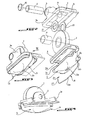
- la figure 2 2 est une vue en perspective éclatée représentant les différents composants de montage du pignon intermédiaire de marche arrière dans la partie du carter de boíte de vitesses ;
- la figure 3 est une vue en perspective semblable à celle de la figure 2 et représentant le pignon intermédiaire de marche arrière en position montée dans la partie du carter ;
- la figure 4 est une vue en perspective de côté suivant la flèche IV de la figure 3 ; et
- la figure 5 est une vue en coupe suivant la ligne V-V de la figure 1.
- Figure 1 is a partial sectional view of the gearbox housing of a motor vehicle and in a part of which is housed the intermediate reverse gear;
- Figure 2 2 is an exploded perspective view showing the various mounting components of the intermediate reverse gear in the part of the gearbox housing;
- Figure 3 is a perspective view similar to that of Figure 2 and showing the intermediate reverse gear in the mounted position in the part of the housing;
- Figure 4 is a side perspective view along arrow IV of Figure 3; and
- FIG. 5 is a sectional view along the line VV in FIG. 1.
En se reportant aux figures, la référence 1 désigne
un carter d'une boíte de vitesses manuelle pour véhicule
automobile et dont seule la partie de logement du pignon
intermédiaire de marche arrière 2 et située au fond du
carter 1, est représentée.Referring to the figures, the reference 1 designates
a manual gearbox housing for vehicle
automobile and only the housing part of the pinion
Le pignon intermédiaire 2 est en engrènement avec
un pignon récepteur de marche arrière 3 et l'arbre
primaire AP comme représenté en figure 5 et est monté à
rotation sur un axe de support 4 fixé dans la partie du
carter la servant de logement au pignon intermédiaire 2.
Selon l'invention, on prévoit un couvercle externe
5 de fermeture de la partie du carter de logement la du
pignon intermédiaire 2 et qui est amoviblement fixé à la
partie la par une agrafe élastique 6, dont les extrémités
s'engagent respectivement dans deux trous borgnes opposés
et alignés 7 de la partie du carter 1a.According to the invention, an external cover is provided.
5 for closing the part of the housing casing
Plus précisément, le couvercle de fermeture 5 est
de forme générale rectangulaire et a sa paroi de
fermeture 5a qui est bombée vers l'extérieur, notamment
dans sa partie centrale. L'agrafe de fixation 6 est
constituée par une tige métallique en forme de U à base
6a allongée et en appui sur la face externe bombée de la
partie centrale de la paroi 5a du couvercle 5 en
s'étendant longitudinalement à cette paroi. Les branches
6b de la tige en forme de U ont leurs extrémités libres
6c recourbées sensiblement à angle droit s'engageant dans
les deux trous borgnes 7. La face externe bombée de la
partie centrale de la paroi 5a du couvercle 5 comporte
une échancrure 5b s'étendant longitudinalement au
couvercle 5 et destinée à recevoir la portion centrale de
la base allongée 6a de la tige 6 en forme de U.More specifically, the
Le couvercle 5 comporte un rebord périphérique 5c
de forme s'emboítant dans une forme conjuguée
périphérique d'un joint d'étanchéité 8 en un matériau à
base de caoutchouc de forme générale rectangulaire et
venant en appui sur le bord plan périphérique 1c
délimitant l'ouverture du logement du pignon
intermédiaire 2 qui fait saillie en partie à travers
cette ouverture, une ouverture rectangulaire 8a du joint
d'étanchéité 8 et dans la partie creuse interne du
couvercle 5. Ainsi, en position de fermeture du couvercle
5, le joint d'étanchéité est plaqué entre le couvercle 5
et le bord périphérique 1c de la partie de carter la par
la force élastique de maintien exercée par l'agrafe de
fixation 6.The
Le pignon intermédiaire 2 est monté fou sur l'axe 4
qui a ses deux extrémités fixées respectivement dans deux
alésages coaxiaux 9 usinés dans la partie du carter la,
l'une des extrémités de l'axe 4 étant en appui au fond de
l'alésage correspondant 9 tandis que l'autre extrémité de
cet axe est retenue dans l'autre alésage 9 par un bouchon
10 fixé à l'entrée de l'alésage 9 et accessible de
l'extérieur pour permettre un démontage éventuel de l'axe
de support 4.The
Le pignon intermédiaire 2 est monté à rotation sur
l'axe de support 4 par l'intermédiaire d'un palier lisse.
tubulaire 11 ou d'une douille à aiguilles et deux
rondelles de friction 13 sont montées sur l'axe 4 de part
et d'autre du pignon intermédiaire 2. A la place de l'une
et/ou l'autre des rondelles de friction 13, il est
possible de prévoir une butée à aiguilles comme
représenté en figure 1 en partie droite de celle-ci.The
L'agencement ci-dessus décrit de l'invention permet d'obtenir un carter de boíte de vitesses moins volumineux, donc d'une masse moindre, un montage et un démontage aisés du pignon intermédiaire de marche arrière et un démoulage simple du carter de boíte de vitesses, tout en restant d'une conception extrêmement simple.The arrangement described above of the invention allows to get a less gearbox housing bulky, therefore less mass, mounting and easy removal of the intermediate reverse gear and a simple demoulding of the gearbox housing, while remaining extremely simple in design.
Claims (6)
- A manual gearbox housing for an automobile vehicle, comprising a housing part (1a) for the reverse idler transmission gear (2), characterised in that it comprises a sealing cover (5) for the housing part (1a) which houses the transmission gear (2), which sealing cover is removably fixed to said part by a clip (6), the ends (6c) of which fit respectively into two blind holes (7) in the housing part (18).
- A housing according to claim 1, characterised in that the sealing cover (5) is fixed to the housing part (1a) via a gasket (8) which bears against the peripheral edge (1c) of the opening in the housing for the transmission gear (2) and which protrudes in part across the opening in the sealing cover (5).
- A housing according to claim 1 or 2, characterised in that the sealing cover (5) is generally rectangular in shape and has its closing wall (5a) bellied towards the outside, and that the fixing clip (6) is a U-shaped metal rod with an elongated base (6a) which bears against the external bellied face of the wall (5a) of the cover (5) longitudinally in relation thereto, and the limbs (6b) of which clip have their free ends (6c) bent back substantially at right angles so that they fit into two blind holes (7) in the housing part (1a).
- A housing according to claim 3, characterised in that the bellied external face of the wall (5a) of the sealing cover (5) comprises an indentation (5b) for receiving the central portion of the elongated base (6a) of the metal rod (6).
- A housing according to any one of the preceding claims, characterised in that it is suitable for receiving the transmission gear (2) which is mounted as an idler gear on a fixed supporting shaft (4) in the housing part (1a), which supporting shaft is mounted at its respective ends in two bores (9) in the housing part (1a) and which is retained therein by a closure plug (10) on one of the two bores (9), which plug is accessible from the outside to enable the supporting shaft (4) for the idler gear (2) to be removed.
- A housing according to claim 5, characterised in that it is suitable for receiving the transmission gear (2) which is mounted on the supporting shaft (4) via a plain bearing (11) and a needle bush, and via friction washers (13) or one or more needle bush stops which are mounted on the supporting shaft (4) on both sides of the transmission gear (2).
Applications Claiming Priority (2)
| Application Number | Priority Date | Filing Date | Title |
|---|---|---|---|
| FR0001635A FR2805019B1 (en) | 2000-02-10 | 2000-02-10 | MANUAL GEARBOX FOR MOTOR VEHICLE |
| FR0001635 | 2000-02-10 |
Publications (2)
| Publication Number | Publication Date |
|---|---|
| EP1126196A1 EP1126196A1 (en) | 2001-08-22 |
| EP1126196B1 true EP1126196B1 (en) | 2003-11-12 |
Family
ID=8846833
Family Applications (1)
| Application Number | Title | Priority Date | Filing Date |
|---|---|---|---|
| EP01400302A Expired - Lifetime EP1126196B1 (en) | 2000-02-10 | 2001-02-07 | Housing for a manual automotive gearbox |
Country Status (5)
| Country | Link |
|---|---|
| EP (1) | EP1126196B1 (en) |
| AT (1) | ATE254252T1 (en) |
| DE (1) | DE60101170T2 (en) |
| ES (1) | ES2210101T3 (en) |
| FR (1) | FR2805019B1 (en) |
Families Citing this family (3)
| Publication number | Priority date | Publication date | Assignee | Title |
|---|---|---|---|---|
| JP2006316866A (en) * | 2005-05-12 | 2006-11-24 | Mazda Motor Corp | Transmission structure |
| DE102006059347A1 (en) | 2006-12-15 | 2008-06-19 | Robert Bosch Gmbh | gearbox |
| DE102014101994A1 (en) * | 2014-02-18 | 2015-08-20 | Getrag Getriebe- Und Zahnradfabrik Hermann Hagenmeyer Gmbh & Cie Kg | Motor vehicle transmission and clamping element |
Family Cites Families (3)
| Publication number | Priority date | Publication date | Assignee | Title |
|---|---|---|---|---|
| GB974944A (en) * | 1962-10-16 | 1964-11-11 | Smith & Sons Ltd S | Improvements in or relating to valve mechanism for placing an induction manifold or a low pressure zone of a carburettor into communication with the crank-case of an internal combustion engine |
| DE2529248C3 (en) * | 1975-07-01 | 1978-10-12 | Zahnradfabrik Friedrichshafen Ag, 7990 Friedrichshafen | Multi-speed reversing gear that can be shifted under load |
| FR2492033A1 (en) * | 1980-10-10 | 1982-04-16 | Renault | Watertight seal for gearbox casing - has flexible sealing ring compressed between body and cover of cast casing |
-
2000
- 2000-02-10 FR FR0001635A patent/FR2805019B1/en not_active Expired - Fee Related
-
2001
- 2001-02-07 DE DE60101170T patent/DE60101170T2/en not_active Expired - Fee Related
- 2001-02-07 EP EP01400302A patent/EP1126196B1/en not_active Expired - Lifetime
- 2001-02-07 AT AT01400302T patent/ATE254252T1/en not_active IP Right Cessation
- 2001-02-07 ES ES01400302T patent/ES2210101T3/en not_active Expired - Lifetime
Also Published As
| Publication number | Publication date |
|---|---|
| DE60101170D1 (en) | 2003-12-18 |
| EP1126196A1 (en) | 2001-08-22 |
| DE60101170T2 (en) | 2004-07-15 |
| ES2210101T3 (en) | 2004-07-01 |
| FR2805019A1 (en) | 2001-08-17 |
| FR2805019B1 (en) | 2002-05-17 |
| ATE254252T1 (en) | 2003-11-15 |
Similar Documents
| Publication | Publication Date | Title |
|---|---|---|
| FR2665507A1 (en) | DEVICE FOR THE RAPID ASSEMBLY OF HOSES TO A HEAT EXCHANGER OF A MOTOR VEHICLE. | |
| FR2662403A1 (en) | ACTUATOR, IN PARTICULAR FOR THE ORIENTATION CONTROL OF A MOTOR VEHICLE PROJECTOR. | |
| CH676156A5 (en) | ||
| EP0459867B1 (en) | Pivot link between a windshield wiper arm and a windshield wiper blade | |
| EP1687526B1 (en) | Internal combustion engine starter comprising a cylinder head and speed reducer centring means on the case | |
| EP1126196B1 (en) | Housing for a manual automotive gearbox | |
| FR2614169A1 (en) | Case for a small electrical appliance | |
| FR2505010A1 (en) | End seal for air conditioning pivoted damper - has shutter provided with resilient tubular sealing lips to run against bearing ends | |
| FR2670726A1 (en) | HEADLIGHT FOR VEHICLE. | |
| FR2625141A1 (en) | Fuel filler spout equipped with an improved closure device controlled from inside the vehicle | |
| FR2764010A1 (en) | Support plate for accessories mounted on panel in motor vehicle | |
| EP0742329B1 (en) | Vehicle locking device comprising improved mounting means for trim cap | |
| EP1728697A1 (en) | Arrangement of a motor vehicle for retaining a window-cleaning-liquid supply pipe | |
| EP1655430B1 (en) | Device for preventing unauthorised operation of the bonnet closure cable of a motor vehicle | |
| FR2739816A1 (en) | PROJECTOR FOR VEHICLES | |
| FR3049016B1 (en) | DEVICE FOR FASTENING A BELLOW ON A GEARBOX CONTROL LEVER. | |
| FR2511738A1 (en) | Detachable vacuum actuator cylinder - has two piece housing with separate housings for actuator rod and piston | |
| FR2708982A1 (en) | Driving device for adjusting pieces of equipment of motor vehicles | |
| FR2674491A1 (en) | Positioning device for pipeline connectors of hydraulic installations for motor vehicles, particularly for hydraulic power-assisted steering units | |
| EP2022921B1 (en) | Device for fixing a glassholder of the screw and nut type | |
| EP0296961A1 (en) | Fixing means | |
| FR2912357A1 (en) | Motor vehicle seat, has unit connecting casing on armature and including trunnion maintained on end of transversal shaft, and casing bowl mounted on trunnion and arranged for being locked in groove, where bowl is connected with casing | |
| FR2618864A1 (en) | GUIDE TUBE FOR CLUTCH LEVERAGE OF MOTOR VEHICLE GEARBOX | |
| FR2478176A1 (en) | Prop for car bonnet - has stop attached to one end by bayonet fixing engaging housing in bonnet | |
| FR2863018A1 (en) | Internal combustion engine starter for use in e.g. tourism vehicle, has crown with central flange having support face, and cylinder head having support face in contact with support face of pinion drive support |
Legal Events
| Date | Code | Title | Description |
|---|---|---|---|
| PUAI | Public reference made under article 153(3) epc to a published international application that has entered the european phase |
Free format text: ORIGINAL CODE: 0009012 |
|
| AK | Designated contracting states |
Kind code of ref document: A1 Designated state(s): AT BE CH CY DE DK ES FI FR GB GR IE IT LI LU MC NL PT SE TR |
|
| AX | Request for extension of the european patent |
Free format text: AL;LT;LV;MK;RO;SI |
|
| 17P | Request for examination filed |
Effective date: 20020208 |
|
| AKX | Designation fees paid |
Free format text: AT BE CH CY DE DK ES FI FR GB GR IE IT LI LU MC NL PT SE TR |
|
| GRAH | Despatch of communication of intention to grant a patent |
Free format text: ORIGINAL CODE: EPIDOS IGRA |
|
| GRAS | Grant fee paid |
Free format text: ORIGINAL CODE: EPIDOSNIGR3 |
|
| GRAA | (expected) grant |
Free format text: ORIGINAL CODE: 0009210 |
|
| AK | Designated contracting states |
Kind code of ref document: B1 Designated state(s): AT BE CH CY DE DK ES FI FR GB GR IE IT LI LU MC NL PT SE TR |
|
| PG25 | Lapsed in a contracting state [announced via postgrant information from national office to epo] |
Ref country code: TR Free format text: LAPSE BECAUSE OF FAILURE TO SUBMIT A TRANSLATION OF THE DESCRIPTION OR TO PAY THE FEE WITHIN THE PRESCRIBED TIME-LIMIT Effective date: 20031112 Ref country code: CY Free format text: LAPSE BECAUSE OF FAILURE TO SUBMIT A TRANSLATION OF THE DESCRIPTION OR TO PAY THE FEE WITHIN THE PRESCRIBED TIME-LIMIT Effective date: 20031112 Ref country code: AT Free format text: LAPSE BECAUSE OF FAILURE TO SUBMIT A TRANSLATION OF THE DESCRIPTION OR TO PAY THE FEE WITHIN THE PRESCRIBED TIME-LIMIT Effective date: 20031112 Ref country code: NL Free format text: LAPSE BECAUSE OF FAILURE TO SUBMIT A TRANSLATION OF THE DESCRIPTION OR TO PAY THE FEE WITHIN THE PRESCRIBED TIME-LIMIT Effective date: 20031112 Ref country code: IE Free format text: LAPSE BECAUSE OF FAILURE TO SUBMIT A TRANSLATION OF THE DESCRIPTION OR TO PAY THE FEE WITHIN THE PRESCRIBED TIME-LIMIT Effective date: 20031112 Ref country code: FI Free format text: LAPSE BECAUSE OF FAILURE TO SUBMIT A TRANSLATION OF THE DESCRIPTION OR TO PAY THE FEE WITHIN THE PRESCRIBED TIME-LIMIT Effective date: 20031112 |
|
| REG | Reference to a national code |
Ref country code: GB Ref legal event code: FG4D Free format text: NOT ENGLISH |
|
| REG | Reference to a national code |
Ref country code: CH Ref legal event code: EP |
|
| REF | Corresponds to: |
Ref document number: 60101170 Country of ref document: DE Date of ref document: 20031218 Kind code of ref document: P |
|
| REG | Reference to a national code |
Ref country code: IE Ref legal event code: FG4D Free format text: FRENCH |
|
| PG25 | Lapsed in a contracting state [announced via postgrant information from national office to epo] |
Ref country code: LU Free format text: LAPSE BECAUSE OF NON-PAYMENT OF DUE FEES Effective date: 20040207 |
|
| PG25 | Lapsed in a contracting state [announced via postgrant information from national office to epo] |
Ref country code: GR Free format text: LAPSE BECAUSE OF FAILURE TO SUBMIT A TRANSLATION OF THE DESCRIPTION OR TO PAY THE FEE WITHIN THE PRESCRIBED TIME-LIMIT Effective date: 20040212 Ref country code: DK Free format text: LAPSE BECAUSE OF FAILURE TO SUBMIT A TRANSLATION OF THE DESCRIPTION OR TO PAY THE FEE WITHIN THE PRESCRIBED TIME-LIMIT Effective date: 20040212 Ref country code: SE Free format text: LAPSE BECAUSE OF FAILURE TO SUBMIT A TRANSLATION OF THE DESCRIPTION OR TO PAY THE FEE WITHIN THE PRESCRIBED TIME-LIMIT Effective date: 20040212 |
|
| PG25 | Lapsed in a contracting state [announced via postgrant information from national office to epo] |
Ref country code: BE Free format text: LAPSE BECAUSE OF NON-PAYMENT OF DUE FEES Effective date: 20040228 Ref country code: MC Free format text: LAPSE BECAUSE OF NON-PAYMENT OF DUE FEES Effective date: 20040228 |
|
| GBT | Gb: translation of ep patent filed (gb section 77(6)(a)/1977) |
Effective date: 20040218 |
|
| NLV1 | Nl: lapsed or annulled due to failure to fulfill the requirements of art. 29p and 29m of the patents act | ||
| REG | Reference to a national code |
Ref country code: IE Ref legal event code: FD4D |
|
| REG | Reference to a national code |
Ref country code: ES Ref legal event code: FG2A Ref document number: 2210101 Country of ref document: ES Kind code of ref document: T3 |
|
| BERE | Be: lapsed |
Owner name: S.A. *PEUGEOT CITROEN AUTOMOBILES Effective date: 20040228 |
|
| PLBE | No opposition filed within time limit |
Free format text: ORIGINAL CODE: 0009261 |
|
| STAA | Information on the status of an ep patent application or granted ep patent |
Free format text: STATUS: NO OPPOSITION FILED WITHIN TIME LIMIT |
|
| 26N | No opposition filed |
Effective date: 20040813 |
|
| PG25 | Lapsed in a contracting state [announced via postgrant information from national office to epo] |
Ref country code: LI Free format text: LAPSE BECAUSE OF NON-PAYMENT OF DUE FEES Effective date: 20050228 Ref country code: CH Free format text: LAPSE BECAUSE OF NON-PAYMENT OF DUE FEES Effective date: 20050228 |
|
| REG | Reference to a national code |
Ref country code: CH Ref legal event code: PL |
|
| REG | Reference to a national code |
Ref country code: GB Ref legal event code: 746 Effective date: 20070119 |
|
| PG25 | Lapsed in a contracting state [announced via postgrant information from national office to epo] |
Ref country code: PT Free format text: LAPSE BECAUSE OF NON-PAYMENT OF DUE FEES Effective date: 20040412 |
|
| PGFP | Annual fee paid to national office [announced via postgrant information from national office to epo] |
Ref country code: ES Payment date: 20080206 Year of fee payment: 8 |
|
| PGFP | Annual fee paid to national office [announced via postgrant information from national office to epo] |
Ref country code: DE Payment date: 20080208 Year of fee payment: 8 Ref country code: GB Payment date: 20080129 Year of fee payment: 8 Ref country code: IT Payment date: 20080212 Year of fee payment: 8 |
|
| PGFP | Annual fee paid to national office [announced via postgrant information from national office to epo] |
Ref country code: FR Payment date: 20080228 Year of fee payment: 8 |
|
| GBPC | Gb: european patent ceased through non-payment of renewal fee |
Effective date: 20090207 |
|
| REG | Reference to a national code |
Ref country code: FR Ref legal event code: ST Effective date: 20091030 |
|
| PG25 | Lapsed in a contracting state [announced via postgrant information from national office to epo] |
Ref country code: DE Free format text: LAPSE BECAUSE OF NON-PAYMENT OF DUE FEES Effective date: 20090901 |
|
| REG | Reference to a national code |
Ref country code: ES Ref legal event code: FD2A Effective date: 20090209 |
|
| PG25 | Lapsed in a contracting state [announced via postgrant information from national office to epo] |
Ref country code: GB Free format text: LAPSE BECAUSE OF NON-PAYMENT OF DUE FEES Effective date: 20090207 Ref country code: FR Free format text: LAPSE BECAUSE OF NON-PAYMENT OF DUE FEES Effective date: 20090302 |
|
| PG25 | Lapsed in a contracting state [announced via postgrant information from national office to epo] |
Ref country code: ES Free format text: LAPSE BECAUSE OF NON-PAYMENT OF DUE FEES Effective date: 20090209 |
|
| PG25 | Lapsed in a contracting state [announced via postgrant information from national office to epo] |
Ref country code: IT Free format text: LAPSE BECAUSE OF NON-PAYMENT OF DUE FEES Effective date: 20090207 |