EP1123463B1 - Systeme d'injection de carburant pour moteur a combustion interne - Google Patents
Systeme d'injection de carburant pour moteur a combustion interne Download PDFInfo
- Publication number
- EP1123463B1 EP1123463B1 EP00958211A EP00958211A EP1123463B1 EP 1123463 B1 EP1123463 B1 EP 1123463B1 EP 00958211 A EP00958211 A EP 00958211A EP 00958211 A EP00958211 A EP 00958211A EP 1123463 B1 EP1123463 B1 EP 1123463B1
- Authority
- EP
- European Patent Office
- Prior art keywords
- pressure
- fuel
- injection system
- fuel injection
- valve
- Prior art date
- Legal status (The legal status is an assumption and is not a legal conclusion. Google has not performed a legal analysis and makes no representation as to the accuracy of the status listed.)
- Expired - Lifetime
Links
Images


Classifications
-
- F—MECHANICAL ENGINEERING; LIGHTING; HEATING; WEAPONS; BLASTING
- F02—COMBUSTION ENGINES; HOT-GAS OR COMBUSTION-PRODUCT ENGINE PLANTS
- F02M—SUPPLYING COMBUSTION ENGINES IN GENERAL WITH COMBUSTIBLE MIXTURES OR CONSTITUENTS THEREOF
- F02M57/00—Fuel-injectors combined or associated with other devices
- F02M57/02—Injectors structurally combined with fuel-injection pumps
- F02M57/022—Injectors structurally combined with fuel-injection pumps characterised by the pump drive
- F02M57/025—Injectors structurally combined with fuel-injection pumps characterised by the pump drive hydraulic, e.g. with pressure amplification
- F02M57/026—Construction details of pressure amplifiers, e.g. fuel passages or check valves arranged in the intensifier piston or head, particular diameter relationships, stop members, arrangement of ports or conduits
-
- F—MECHANICAL ENGINEERING; LIGHTING; HEATING; WEAPONS; BLASTING
- F02—COMBUSTION ENGINES; HOT-GAS OR COMBUSTION-PRODUCT ENGINE PLANTS
- F02M—SUPPLYING COMBUSTION ENGINES IN GENERAL WITH COMBUSTIBLE MIXTURES OR CONSTITUENTS THEREOF
- F02M41/00—Fuel-injection apparatus with two or more injectors fed from a common pressure-source sequentially by means of a distributor
- F02M41/02—Fuel-injection apparatus with two or more injectors fed from a common pressure-source sequentially by means of a distributor the distributor being spaced from pumping elements
- F02M41/06—Fuel-injection apparatus with two or more injectors fed from a common pressure-source sequentially by means of a distributor the distributor being spaced from pumping elements the distributor rotating
-
- F—MECHANICAL ENGINEERING; LIGHTING; HEATING; WEAPONS; BLASTING
- F02—COMBUSTION ENGINES; HOT-GAS OR COMBUSTION-PRODUCT ENGINE PLANTS
- F02M—SUPPLYING COMBUSTION ENGINES IN GENERAL WITH COMBUSTIBLE MIXTURES OR CONSTITUENTS THEREOF
- F02M45/00—Fuel-injection apparatus characterised by having a cyclic delivery of specific time/pressure or time/quantity relationship
-
- F—MECHANICAL ENGINEERING; LIGHTING; HEATING; WEAPONS; BLASTING
- F02—COMBUSTION ENGINES; HOT-GAS OR COMBUSTION-PRODUCT ENGINE PLANTS
- F02M—SUPPLYING COMBUSTION ENGINES IN GENERAL WITH COMBUSTIBLE MIXTURES OR CONSTITUENTS THEREOF
- F02M47/00—Fuel-injection apparatus operated cyclically with fuel-injection valves actuated by fluid pressure
- F02M47/02—Fuel-injection apparatus operated cyclically with fuel-injection valves actuated by fluid pressure of accumulator-injector type, i.e. having fuel pressure of accumulator tending to open, and fuel pressure in other chamber tending to close, injection valves and having means for periodically releasing that closing pressure
- F02M47/027—Electrically actuated valves draining the chamber to release the closing pressure
-
- F—MECHANICAL ENGINEERING; LIGHTING; HEATING; WEAPONS; BLASTING
- F02—COMBUSTION ENGINES; HOT-GAS OR COMBUSTION-PRODUCT ENGINE PLANTS
- F02M—SUPPLYING COMBUSTION ENGINES IN GENERAL WITH COMBUSTIBLE MIXTURES OR CONSTITUENTS THEREOF
- F02M57/00—Fuel-injectors combined or associated with other devices
- F02M57/02—Injectors structurally combined with fuel-injection pumps
- F02M57/022—Injectors structurally combined with fuel-injection pumps characterised by the pump drive
- F02M57/025—Injectors structurally combined with fuel-injection pumps characterised by the pump drive hydraulic, e.g. with pressure amplification
-
- F—MECHANICAL ENGINEERING; LIGHTING; HEATING; WEAPONS; BLASTING
- F02—COMBUSTION ENGINES; HOT-GAS OR COMBUSTION-PRODUCT ENGINE PLANTS
- F02M—SUPPLYING COMBUSTION ENGINES IN GENERAL WITH COMBUSTIBLE MIXTURES OR CONSTITUENTS THEREOF
- F02M59/00—Pumps specially adapted for fuel-injection and not provided for in groups F02M39/00 -F02M57/00, e.g. rotary cylinder-block type of pumps
- F02M59/02—Pumps specially adapted for fuel-injection and not provided for in groups F02M39/00 -F02M57/00, e.g. rotary cylinder-block type of pumps of reciprocating-piston or reciprocating-cylinder type
- F02M59/10—Pumps specially adapted for fuel-injection and not provided for in groups F02M39/00 -F02M57/00, e.g. rotary cylinder-block type of pumps of reciprocating-piston or reciprocating-cylinder type characterised by the piston-drive
- F02M59/105—Pumps specially adapted for fuel-injection and not provided for in groups F02M39/00 -F02M57/00, e.g. rotary cylinder-block type of pumps of reciprocating-piston or reciprocating-cylinder type characterised by the piston-drive hydraulic drive
-
- F—MECHANICAL ENGINEERING; LIGHTING; HEATING; WEAPONS; BLASTING
- F02—COMBUSTION ENGINES; HOT-GAS OR COMBUSTION-PRODUCT ENGINE PLANTS
- F02M—SUPPLYING COMBUSTION ENGINES IN GENERAL WITH COMBUSTIBLE MIXTURES OR CONSTITUENTS THEREOF
- F02M63/00—Other fuel-injection apparatus having pertinent characteristics not provided for in groups F02M39/00 - F02M57/00 or F02M67/00; Details, component parts, or accessories of fuel-injection apparatus, not provided for in, or of interest apart from, the apparatus of groups F02M39/00 - F02M61/00 or F02M67/00; Combination of fuel pump with other devices, e.g. lubricating oil pump
- F02M63/02—Fuel-injection apparatus having several injectors fed by a common pumping element, or having several pumping elements feeding a common injector; Fuel-injection apparatus having provisions for cutting-out pumps, pumping elements, or injectors; Fuel-injection apparatus having provisions for variably interconnecting pumping elements and injectors alternatively
- F02M63/0225—Fuel-injection apparatus having a common rail feeding several injectors ; Means for varying pressure in common rails; Pumps feeding common rails
Definitions
- the invention is based on a fuel injection system for an internal combustion engine according to the preamble of the claim 1.
- Such an injection system is for example by the DE 41 18 237 A has become known.
- a pressure-controlled fuel injection system is controlled by the pressure prevailing in the nozzle chamber of an injector fuel pressure valve body (eg a nozzle needle) against the action of a closing force and thus released the injection port for injection of the fuel.
- the pressure with which fuel exits the nozzle chamber into the cylinder is referred to as injection pressure.
- a stroke-controlled fuel injection system is understood to mean that the opening and closing of the injection opening of an injector take place by means of a displaceable valve member due to the hydraulic interaction of the fuel pressures in a nozzle space and in a control space.
- an arrangement will be referred to as central if it is common to all cylinders, and local if provided for only a single cylinder.
- a disadvantage of this known fuel injection system is that first of all the fuel only to the higher Pressure level must be compressed, then one Part of the fuel back to the lower pressure level relieve.
- two pressure accumulators are required to store the two fuel pressures.
- the high pressure pump is because it is driven by the camshaft of the engine is, permanently in the enterprise and also then, if the desired pressure in the respective accumulator already is constructed. This permanent high pressure generation and the subsequent relief to the low pressure level a better efficiency.
- High pressure accumulator is the fuel pressure for strength reasons currently limited to a maximum of about 1800 bar.
- WO 98/09068 From WO 98/09068 is a stroke-controlled injection system known, in which also two pressure accumulator for storage the two fuel pressures are provided. For each Accumulator is provided its own high-pressure pump, which is permanently in operation and even if the desired pressure already built up in the respective accumulator is.
- the invention is defined by the features of claim 1.
- a second higher pressure level by means of a pressure booster generated. Because this translated pressure is not in one Pressure accumulator is stored, can be a higher injection pressure be achieved. Both pressure levels can be used for Representation of a flexible injection such as a boat-shaped Injection, pre and post injection used become.
- first embodiment of a pressure-controlled fuel injection system 1 promotes a high pressure pump 2 fuel 3 from a storage tank 4 via a feed line 5 to a central pressure booster unit 6 at high pressure, which is constructed by energizing a 2/2-way valve 7 ,
- the high-pressure pump 2 can produce a first (lower) fuel pressure of about 300 to about 1000 bar and, for example, be a cam pump with injection adjuster similar to the distributor injection pump known from DE 35 16 867 A1.
- an even higher fuel pressure can be generated via the central pressure booster unit 6.
- an injection pressure of more than 2000 bar can be realized.
- the respectively present fuel pressure is then distributed from a central distribution device 8 to a plurality of high-pressure lines 9 corresponding to the number of individual cylinders, which discharge to the individual injectors 10 (injection device) projecting into the combustion chamber of the internal combustion engine to be supplied.
- a central distribution device 8 to a plurality of high-pressure lines 9 corresponding to the number of individual cylinders, which discharge to the individual injectors 10 (injection device) projecting into the combustion chamber of the internal combustion engine to be supplied.
- Fig. 1 only one of the injectors 10 is shown in more detail.
- the central pressure booster unit 6 comprises a pressure booster 11 with a pressure means 12 in the form of a displaceable piston element, which can be connected at one end to the delivery line 5 by means of a valve unit 13 , so that it is pressurized by the fuel located in a primary chamber 14 at one end.
- a differential space 15 is depressurized by means of a leakage line 16 , so that the pressure medium 12 can be displaced in the compression direction to reduce the volume of a pressure chamber 17 .
- the fuel in the pressure chamber 17 is compressed corresponding to the area ratio of the primary chamber 14 and the pressure chamber 17 to the higher fuel pressure.
- the pressure booster 11 can be bypassed by a parallel bypass line 19 , which can be activated or deactivated by means of the valve unit 13.
- the valve unit 13 is formed in front of the pressure booster 11 and as a 3/2-way valve.
- the parts 11, 13 and 19 form the central pressure booster unit 6.
- the respectively present at the manifold 8 fuel pressure is passed through the pressure line 9 into a nozzle chamber 20 of the injector 10.
- the injection is pressure-controlled by means of an axially displaceable in a guide bore piston-shaped valve member 21 (nozzle needle), the conical valve sealing surface 22 cooperates with a valve seat surface on the injector and thus closes the injection openings 23 provided there.
- the nozzle chamber 20 a in the opening direction of the valve member 21 facing pressure surface of the valve member 21 is exposed to the pressure prevailing there, wherein the nozzle chamber 20 continues through an annular gap between the valve member 21 and the guide bore to the valve sealing surface 22 of the injector 10.
- each injector 10 By the pressure prevailing in the nozzle chamber 20 pressure, the injection openings 23 sealing valve member 21 is controlled against the action of a closing force (closing spring 24 ), wherein the spring chamber 25 is depressurized by means of a leakage line 26 .
- a check valve assembly 27 Behind the manifold 8 for each injector 10 each still a check valve assembly 27 is provided which allows the fuel in the direction of the injector 10 via a first check valve 28 and the return of fuel from the injector 10 by means of a throttle 29 and a second check valve 30 to relieve the Distributor 8 and the pressure reduction permits.
- a pre-injection with the lower fuel pressure takes place in de-energized valve unit 13 by energizing the 2/2-way valve 7. By energizing also the valve unit 13 then takes the main injection with the higher Fuel pressure. For a post-injection with the deeper Fuel pressure, the valve unit 13 back in switched back to the de-energized state. Will the primary chamber 14 with the help of the valve unit 13 at no-current 2/2-way valve 7 connected to the input of the high pressure pump 2, so the provision of the pressure medium done 12 and the refilling of the pressure chamber 17, over the check valve 18 is connected to the delivery line 5 is.
- valve unit 13a is formed behind the pressure booster 11 and a 2/2-way valve, which is decoupled from the bypass line 19 via a check valve 31 .
- the parts 11, 13a, 19 and 31 form the central pressure booster unit 6a.
- the pressure booster unit 41 is not provided centrally but locally for each injector 10 individually.
- the local pressure booster unit 41 like the central pressure booster unit 6 shown in FIG. 1 a, comprises a pressure booster 42 with a check valve 43 and a valve unit 44 for switching between the pressure booster 42 and the bypass duct 45.
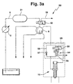
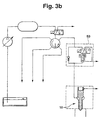
- the high-pressure pump 2 conveys the fuel via the delivery line 5 into a central pressure accumulator 51 (common rail), in which the fuel is stored under a pressure of approximately 300 to approximately 600 bar.
- a central valve unit 52 eg, a 3/2-way valve
- the fuel from the pressure accumulator 51 via the central distribution device 8 is forwarded to the individual pressure-controlled injectors 10.
- Each injector 10 is associated with a local pressure booster unit 53 with a pressure booster 54 , by means of which, if necessary from the lower fuel pressure of the pressure accumulator 51, a higher fuel pressure can be generated.
- the local pressure booster 54 Via the valve unit 55 (3/2-way valve), the local pressure booster 54, which is constructed analogously to the central pressure booster 11, are activated.
- the pressure chamber 56 of the local pressure booster 54 is filled with fuel from the pressure accumulator 51, wherein a check valve 57 in a bypass line 58 parallel to the pressure booster 54 prevents the return of compressed fuel back into the pressure accumulator 51.
- the parts 54, 55, 57 and 58 form the local pressure booster unit 53, which may be either inside the injector housing ( FIG. 3a ) or outside ( FIG. 3b ).
- a pilot injection with the lower fuel pressure of the central pressure accumulator 51 takes place with currentless valve unit 55 by energizing the central 3/2-way valve 52. By energizing the valve unit 55 and then the main injection with the higher fuel pressure. For a post-injection with the lower fuel pressure, the valve unit 55 is switched back to the de-energized state. At the end of the injection, the central valve unit 52 is switched back to leakage 59 and thus the manifold 8 and the injector 10 relieved.
- the injection system 60 shown in Fig. 4 differs by the use of stroke-controlled injectors 61 and the formation of the central valve unit 62 as a 2/2-way valve.
- the pressure-controlled injector 10 of FIG. 1 engages in a stroke-controlled injector 61 on the valve member 21 coaxial with the valve spring 23 to a pressure piece 63 , which limits the valve sealing surface 22 remote from the end face 64 a control chamber 65.
- the control chamber 65 has a fuel inlet from the pressure line 9 with a first throttle 66 and a fuel outlet to a pressure relief line 67 with a second throttle 68, which is controllable by a 2/2-way valve 69 to 70 leakage.
- the pressure piece 63 is pressurized in the closing direction. Under the lower or higher fuel pressure stagnant fuel constantly fills the nozzle chamber 20 and the control chamber 65.
- the pressure in the control chamber 65 can be reduced, so that in the sequence on the opening direction the valve member 21 acting pressure force in the nozzle chamber 20 exceeds the force acting in the closing direction on the valve member 21 pressing force.
- the valve sealing surface 22 lifts off the valve seat surface and fuel is injected. In this case, the pressure relief process of the control chamber 65 and thus the stroke control of the valve member 21 via the dimensioning of the two throttles 66 and 68 can be influenced.
- the end of the injection is initiated by renewed actuation (closing) of the 2/2-way valve 69, which decouples the control chamber 65 again from the leakage line 70, so that in the control chamber 65 again a pressure builds up, the pressure piece 63 in the closing direction can move.
- the switching of the fuel to either the lower or the higher fuel pressure occurs for each injector 61 in the local pressure booster unit 53 through the valve unit 55.
- the pressure booster unit 53 can be arranged either inside the injector housing ( FIG. 4a ) or outside ( FIG. 4b ).
- a fuel injection system 1 for an internal combustion engine different with the fuel with at least two high fuel pressures via injectors 10 in the combustion chamber of the internal combustion engine to be injected can, parallel to a bypass line 19 is a hydraulic Pressure booster 11 for generating the higher fuel pressure provided, wherein the pressure booster 11 via a valve unit 13 can be activated and deactivated. Since the intensifier is not permanently in operation and even the losses are reduced by friction, is the Improved efficiency.
Landscapes
- Engineering & Computer Science (AREA)
- Chemical & Material Sciences (AREA)
- Combustion & Propulsion (AREA)
- Mechanical Engineering (AREA)
- General Engineering & Computer Science (AREA)
- Physics & Mathematics (AREA)
- Fluid Mechanics (AREA)
- Fuel-Injection Apparatus (AREA)
Claims (7)
- Système d'injection de carburant (1) pour un moteur à combustion interne, dans lequel du carburant qui a au moins deux pressions de niveau différent peut être injecté dans la chambre de combustion du moteur à combustion interne par l'intermédiaire d'injecteurs (10) ; en prévoyant alors en parallèle à une conduite de dérivation (19) un amplificateur de pression (11) hydraulique pour produire la pression la plus élevée du carburant, l'amplificateur de pression (11) pouvant être activé et désactivé par l'intermédiaire d'une unité de soupapes (13 ; 13a),
caractérisé en ce qu'
l'amplificateur de pression (11) est central pour tous les injecteurs (10) et une installation de distribution (8) répartit la pression du carburant sur chaque injecteur (10). - Système d'injection de carburant selon la revendication 1,
caractérisé en ce que
la conduite de dérivation (19) est fermée lorsque l'amplificateur de pression (11) est activé. - Système d'injection de carburant selon la revendication 1 ou 2,
caractérisé en ce que
l'unité de soupapes (13) est en amont de l'amplificateur de pression (11). - Système d'injection de carburant selon la revendication 1 ou 2,
caractérisé en ce que
l'unité de soupapes (13a) est en aval de l'amplificateur de pression (11). - Système d'injection de carburant selon l'une des revendications précédentes,
caractérisé en ce qu'
au moins un réservoir de pression central stocke la pression la plus basse de carburant. - Système d'injection de carburant selon l'une des revendications précédentes,
caractérisé en ce que
les injecteurs (10) sont commandés par pression. - Système d'injection de carburant selon l'une des revendications précédentes,
caractérisé en ce que
les injecteurs sont commandés en course de déplacement.
Applications Claiming Priority (3)
| Application Number | Priority Date | Filing Date | Title |
|---|---|---|---|
| DE19939423A DE19939423A1 (de) | 1999-08-20 | 1999-08-20 | Kraftstoffeinspritzsystem für eine Brennkraftmaschine |
| DE19939423 | 1999-08-20 | ||
| PCT/DE2000/002581 WO2001014727A1 (fr) | 1999-08-20 | 2000-08-02 | Systeme d'injection de carburant pour moteur a combustion interne |
Publications (2)
| Publication Number | Publication Date |
|---|---|
| EP1123463A1 EP1123463A1 (fr) | 2001-08-16 |
| EP1123463B1 true EP1123463B1 (fr) | 2005-03-30 |
Family
ID=7918958
Family Applications (1)
| Application Number | Title | Priority Date | Filing Date |
|---|---|---|---|
| EP00958211A Expired - Lifetime EP1123463B1 (fr) | 1999-08-20 | 2000-08-02 | Systeme d'injection de carburant pour moteur a combustion interne |
Country Status (6)
| Country | Link |
|---|---|
| US (1) | US6688277B1 (fr) |
| EP (1) | EP1123463B1 (fr) |
| JP (1) | JP2003507651A (fr) |
| AT (1) | ATE292238T1 (fr) |
| DE (2) | DE19939423A1 (fr) |
| WO (1) | WO2001014727A1 (fr) |
Cited By (3)
| Publication number | Priority date | Publication date | Assignee | Title |
|---|---|---|---|---|
| DE102007010495A1 (de) | 2007-03-05 | 2008-09-11 | Robert Bosch Gmbh | Kraftstoffeinspritzsystem sowie Druckverstärkungseinrichtung für ein Kraftstoffeinspritzsystem |
| DE102007014455A1 (de) | 2007-03-21 | 2008-09-25 | Iav Gmbh Ingenieurgesellschaft Auto Und Verkehr | Kraftstoffeinspritzsystem für eine Brennkraftmaschine |
| DE102007021327A1 (de) | 2007-05-07 | 2008-11-13 | Robert Bosch Gmbh | Kraftstoffeinspritzsystem mit Druckverstärkung |
Families Citing this family (12)
| Publication number | Priority date | Publication date | Assignee | Title |
|---|---|---|---|---|
| DE19939422A1 (de) * | 1999-08-20 | 2001-03-01 | Bosch Gmbh Robert | Kraftstoffeinspritzsystem für eine Brennkraftmaschine |
| DE10060089A1 (de) * | 2000-12-02 | 2002-06-20 | Bosch Gmbh Robert | Kraftstoffeinspritzeinrichtung |
| US6568369B1 (en) * | 2000-12-05 | 2003-05-27 | Caterpillar Inc | Common rail injector with separately controlled pilot and main injection |
| DE10229419A1 (de) * | 2002-06-29 | 2004-01-29 | Robert Bosch Gmbh | Druckübersetzter Kraftstoffinjektor mit schnellem Druckabbau bei Einspritzende |
| JP4308487B2 (ja) * | 2002-07-11 | 2009-08-05 | 株式会社豊田中央研究所 | 燃料噴射装置における燃料噴射方法 |
| WO2004072470A1 (fr) * | 2003-02-12 | 2004-08-26 | Robert Bosch Gmbh | Systeme de pompe d'injection de carburant comportant un mecanisme de post-injection haute pression |
| DE102004010760A1 (de) * | 2004-03-05 | 2005-09-22 | Robert Bosch Gmbh | Kraftstoffeinspritzeinrichtung für Brennkraftmaschinen mit Nadelhubdämpfung |
| JP3994990B2 (ja) | 2004-07-21 | 2007-10-24 | 株式会社豊田中央研究所 | 燃料噴射装置 |
| EP1717434A1 (fr) * | 2005-04-28 | 2006-11-02 | Delphi Technologies, Inc. | Amélioration d'un système d'injection de carburant |
| DE102005033123B3 (de) * | 2005-07-15 | 2006-12-21 | L'orange Gmbh | Kraftstoffinjektor |
| US7693984B2 (en) * | 2005-12-29 | 2010-04-06 | Panasonic Electric Works Co., Ltd. | Systems and methods for providing current status data to a requesting device |
| GB201117160D0 (en) * | 2011-10-05 | 2011-11-16 | Rolls Royce Goodrich Engine Control Systems Ltd | Fuel system |
Citations (1)
| Publication number | Priority date | Publication date | Assignee | Title |
|---|---|---|---|---|
| WO2000055496A1 (fr) * | 1999-03-12 | 2000-09-21 | Robert Bosch Gmbh | Systeme d'injection de carburant |
Family Cites Families (10)
| Publication number | Priority date | Publication date | Assignee | Title |
|---|---|---|---|---|
| US4142497A (en) * | 1975-11-06 | 1979-03-06 | Allied Chemical Corporation | Fuel pressure booster and regulator |
| DE3618447A1 (de) * | 1986-05-31 | 1987-12-03 | Bosch Gmbh Robert | Kraftstoffeinspritzvorrichtung fuer brennkraftmaschinen |
| DE3629754C2 (de) | 1986-09-01 | 1994-07-14 | Bosch Gmbh Robert | Vorrichtung zur Erzeugung von Voreinspritzungen bei Pumpedüsen |
| AT408133B (de) * | 1990-06-08 | 2001-09-25 | Avl Verbrennungskraft Messtech | Einspritzsystem für brennkraftmaschinen |
| US5355856A (en) * | 1992-07-23 | 1994-10-18 | Paul Marius A | High pressure differential fuel injector |
| JP2885076B2 (ja) * | 1994-07-08 | 1999-04-19 | 三菱自動車工業株式会社 | 蓄圧式燃料噴射装置 |
| GB9422864D0 (en) * | 1994-11-12 | 1995-01-04 | Lucas Ind Plc | Fuel system |
| JP3476202B2 (ja) * | 1996-08-29 | 2003-12-10 | 三菱ふそうトラックバス株式会社 | 燃料噴射装置 |
| DE19716221B4 (de) | 1997-04-18 | 2007-06-21 | Robert Bosch Gmbh | Kraftstoffeinspritzeinrichtung mit Vor- und Haupteinspritzung bei Brennkraftmaschinen, insbesondere für schwer zündbare Kraftstoffe |
| DE19939429A1 (de) * | 1999-08-20 | 2001-03-01 | Bosch Gmbh Robert | Kraftstoffeinspritzeinrichtung |
-
1999
- 1999-08-20 DE DE19939423A patent/DE19939423A1/de not_active Ceased
-
2000
- 2000-08-02 JP JP2001518576A patent/JP2003507651A/ja active Pending
- 2000-08-02 WO PCT/DE2000/002581 patent/WO2001014727A1/fr active IP Right Grant
- 2000-08-02 DE DE50009918T patent/DE50009918D1/de not_active Expired - Lifetime
- 2000-08-02 EP EP00958211A patent/EP1123463B1/fr not_active Expired - Lifetime
- 2000-08-02 US US09/807,881 patent/US6688277B1/en not_active Expired - Fee Related
- 2000-08-02 AT AT00958211T patent/ATE292238T1/de not_active IP Right Cessation
Patent Citations (1)
| Publication number | Priority date | Publication date | Assignee | Title |
|---|---|---|---|---|
| WO2000055496A1 (fr) * | 1999-03-12 | 2000-09-21 | Robert Bosch Gmbh | Systeme d'injection de carburant |
Cited By (5)
| Publication number | Priority date | Publication date | Assignee | Title |
|---|---|---|---|---|
| DE102007010495A1 (de) | 2007-03-05 | 2008-09-11 | Robert Bosch Gmbh | Kraftstoffeinspritzsystem sowie Druckverstärkungseinrichtung für ein Kraftstoffeinspritzsystem |
| WO2008107220A1 (fr) | 2007-03-05 | 2008-09-12 | Robert Bosch Gmbh | Système d'injection de carburant et dispositif d'amplification de pression pour un système d'injection de carburant |
| EP2402588A1 (fr) | 2007-03-05 | 2012-01-04 | Robert Bosch GmbH | Système d'injection de carburant |
| DE102007014455A1 (de) | 2007-03-21 | 2008-09-25 | Iav Gmbh Ingenieurgesellschaft Auto Und Verkehr | Kraftstoffeinspritzsystem für eine Brennkraftmaschine |
| DE102007021327A1 (de) | 2007-05-07 | 2008-11-13 | Robert Bosch Gmbh | Kraftstoffeinspritzsystem mit Druckverstärkung |
Also Published As
| Publication number | Publication date |
|---|---|
| EP1123463A1 (fr) | 2001-08-16 |
| ATE292238T1 (de) | 2005-04-15 |
| DE50009918D1 (de) | 2005-05-04 |
| US6688277B1 (en) | 2004-02-10 |
| JP2003507651A (ja) | 2003-02-25 |
| WO2001014727A1 (fr) | 2001-03-01 |
| DE19939423A1 (de) | 2001-03-01 |
Similar Documents
| Publication | Publication Date | Title |
|---|---|---|
| EP1125046B1 (fr) | System d'injection de carburant pour un moteur à combustion interne avec un multiplicateur de pression | |
| EP1125049B1 (fr) | Procede et systeme d'injection de carburant combinee par levee/pression pour moteur a combustion interne | |
| EP1078160B1 (fr) | Systeme d'injection de carburant | |
| EP1125058B1 (fr) | Systeme d'injection de carburant pour moteur a combustion interne | |
| EP1123462B1 (fr) | Dispositif d'injection de carburant | |
| DE19939420B4 (de) | Kraftstoffeinspritzverfahren und -system für eine Brennkraftmaschine | |
| DE10065103C1 (de) | Kraftstoffeinspritzeinrichtung | |
| EP1123463B1 (fr) | Systeme d'injection de carburant pour moteur a combustion interne | |
| DE102007021327A1 (de) | Kraftstoffeinspritzsystem mit Druckverstärkung | |
| EP1125045B1 (fr) | Systeme d'injection de carburant pour un moteur a combustion interne | |
| EP1370762B1 (fr) | Dispositif d'injection de carburant | |
| EP1273797B1 (fr) | Dispositif d'injection de combustible | |
| DE19939428A1 (de) | Verfahren und Vorrichtung zur Durchführung einer Kraftstoffeinspritzung | |
| EP1121527B1 (fr) | Dispositif d'injection de carburant | |
| DE19939425B4 (de) | Kraftstoffeinspritzsystem für eine Brennkraftmaschine | |
| WO2004020817A1 (fr) | Dispositif d'injection de carburant | |
| EP1354133A2 (fr) | Dispositif d'injection de carburant | |
| EP1125044B1 (fr) | Systeme d'injection de carburant pour moteur a combustion interne | |
| WO2002055869A1 (fr) | Dispositif d'injection de carburant | |
| EP1144840A1 (fr) | Systeme d'injection de carburant |
Legal Events
| Date | Code | Title | Description |
|---|---|---|---|
| PUAI | Public reference made under article 153(3) epc to a published international application that has entered the european phase |
Free format text: ORIGINAL CODE: 0009012 |
|
| AK | Designated contracting states |
Kind code of ref document: A1 Designated state(s): AT BE CH CY DE DK ES FI FR GB GR IE IT LI LU MC NL PT SE |
|
| 17P | Request for examination filed |
Effective date: 20010903 |
|
| 17Q | First examination report despatched |
Effective date: 20040415 |
|
| GRAP | Despatch of communication of intention to grant a patent |
Free format text: ORIGINAL CODE: EPIDOSNIGR1 |
|
| GRAS | Grant fee paid |
Free format text: ORIGINAL CODE: EPIDOSNIGR3 |
|
| GRAA | (expected) grant |
Free format text: ORIGINAL CODE: 0009210 |
|
| AK | Designated contracting states |
Kind code of ref document: B1 Designated state(s): AT BE CH CY DE DK ES FI FR GB GR IE IT LI LU MC NL PT SE |
|
| PG25 | Lapsed in a contracting state [announced via postgrant information from national office to epo] |
Ref country code: IT Free format text: LAPSE BECAUSE OF FAILURE TO SUBMIT A TRANSLATION OF THE DESCRIPTION OR TO PAY THE FEE WITHIN THE PRE;WARNING: LAPSES OF ITALIAN PATENTS WITH EFFECTIVE DATE BEFORE 2007 MAY HAVE OCCURRED AT ANY TIME BEFORE 2007. THE CORRECT EFFECTIVE DATE MAY BE DIFFERENT FROM THE ONE RECORDED.SCRIBED TIME-LIMIT Effective date: 20050330 Ref country code: IE Free format text: LAPSE BECAUSE OF FAILURE TO SUBMIT A TRANSLATION OF THE DESCRIPTION OR TO PAY THE FEE WITHIN THE PRESCRIBED TIME-LIMIT Effective date: 20050330 Ref country code: FI Free format text: LAPSE BECAUSE OF FAILURE TO SUBMIT A TRANSLATION OF THE DESCRIPTION OR TO PAY THE FEE WITHIN THE PRESCRIBED TIME-LIMIT Effective date: 20050330 Ref country code: GB Free format text: LAPSE BECAUSE OF FAILURE TO SUBMIT A TRANSLATION OF THE DESCRIPTION OR TO PAY THE FEE WITHIN THE PRESCRIBED TIME-LIMIT Effective date: 20050330 Ref country code: NL Free format text: LAPSE BECAUSE OF FAILURE TO SUBMIT A TRANSLATION OF THE DESCRIPTION OR TO PAY THE FEE WITHIN THE PRESCRIBED TIME-LIMIT Effective date: 20050330 |
|
| REG | Reference to a national code |
Ref country code: GB Ref legal event code: FG4D Free format text: NOT ENGLISH |
|
| REG | Reference to a national code |
Ref country code: CH Ref legal event code: EP |
|
| REF | Corresponds to: |
Ref document number: 50009918 Country of ref document: DE Date of ref document: 20050504 Kind code of ref document: P |
|
| REG | Reference to a national code |
Ref country code: IE Ref legal event code: FG4D Free format text: LANGUAGE OF EP DOCUMENT: GERMAN |
|
| PG25 | Lapsed in a contracting state [announced via postgrant information from national office to epo] |
Ref country code: DK Free format text: LAPSE BECAUSE OF FAILURE TO SUBMIT A TRANSLATION OF THE DESCRIPTION OR TO PAY THE FEE WITHIN THE PRESCRIBED TIME-LIMIT Effective date: 20050630 Ref country code: GR Free format text: LAPSE BECAUSE OF FAILURE TO SUBMIT A TRANSLATION OF THE DESCRIPTION OR TO PAY THE FEE WITHIN THE PRESCRIBED TIME-LIMIT Effective date: 20050630 |
|
| PG25 | Lapsed in a contracting state [announced via postgrant information from national office to epo] |
Ref country code: ES Free format text: LAPSE BECAUSE OF FAILURE TO SUBMIT A TRANSLATION OF THE DESCRIPTION OR TO PAY THE FEE WITHIN THE PRESCRIBED TIME-LIMIT Effective date: 20050711 |
|
| PG25 | Lapsed in a contracting state [announced via postgrant information from national office to epo] |
Ref country code: LU Free format text: LAPSE BECAUSE OF NON-PAYMENT OF DUE FEES Effective date: 20050802 Ref country code: AT Free format text: LAPSE BECAUSE OF NON-PAYMENT OF DUE FEES Effective date: 20050802 Ref country code: CY Free format text: LAPSE BECAUSE OF FAILURE TO SUBMIT A TRANSLATION OF THE DESCRIPTION OR TO PAY THE FEE WITHIN THE PRESCRIBED TIME-LIMIT Effective date: 20050802 |
|
| PG25 | Lapsed in a contracting state [announced via postgrant information from national office to epo] |
Ref country code: CH Free format text: LAPSE BECAUSE OF NON-PAYMENT OF DUE FEES Effective date: 20050831 Ref country code: BE Free format text: LAPSE BECAUSE OF NON-PAYMENT OF DUE FEES Effective date: 20050831 Ref country code: LI Free format text: LAPSE BECAUSE OF NON-PAYMENT OF DUE FEES Effective date: 20050831 Ref country code: MC Free format text: LAPSE BECAUSE OF NON-PAYMENT OF DUE FEES Effective date: 20050831 |
|
| PG25 | Lapsed in a contracting state [announced via postgrant information from national office to epo] |
Ref country code: PT Free format text: LAPSE BECAUSE OF FAILURE TO SUBMIT A TRANSLATION OF THE DESCRIPTION OR TO PAY THE FEE WITHIN THE PRESCRIBED TIME-LIMIT Effective date: 20050907 |
|
| NLV1 | Nl: lapsed or annulled due to failure to fulfill the requirements of art. 29p and 29m of the patents act | ||
| GBV | Gb: ep patent (uk) treated as always having been void in accordance with gb section 77(7)/1977 [no translation filed] |
Effective date: 20050330 |
|
| REG | Reference to a national code |
Ref country code: IE Ref legal event code: FD4D |
|
| PLBE | No opposition filed within time limit |
Free format text: ORIGINAL CODE: 0009261 |
|
| STAA | Information on the status of an ep patent application or granted ep patent |
Free format text: STATUS: NO OPPOSITION FILED WITHIN TIME LIMIT |
|
| 26N | No opposition filed |
Effective date: 20060102 |
|
| REG | Reference to a national code |
Ref country code: CH Ref legal event code: PL |
|
| EN | Fr: translation not filed | ||
| BERE | Be: lapsed |
Owner name: ROBERT BOSCH G.M.B.H. Effective date: 20050831 |
|
| PG25 | Lapsed in a contracting state [announced via postgrant information from national office to epo] |
Ref country code: SE Free format text: LAPSE BECAUSE OF FAILURE TO SUBMIT A TRANSLATION OF THE DESCRIPTION OR TO PAY THE FEE WITHIN THE PRESCRIBED TIME-LIMIT Effective date: 20050630 |
|
| PG25 | Lapsed in a contracting state [announced via postgrant information from national office to epo] |
Ref country code: FR Free format text: LAPSE BECAUSE OF NON-PAYMENT OF DUE FEES Effective date: 20050831 |
|
| PG25 | Lapsed in a contracting state [announced via postgrant information from national office to epo] |
Ref country code: FR Free format text: LAPSE BECAUSE OF NON-PAYMENT OF DUE FEES Effective date: 20050330 |
|
| PGFP | Annual fee paid to national office [announced via postgrant information from national office to epo] |
Ref country code: DE Payment date: 20141024 Year of fee payment: 15 |
|
| REG | Reference to a national code |
Ref country code: DE Ref legal event code: R119 Ref document number: 50009918 Country of ref document: DE |
|
| PG25 | Lapsed in a contracting state [announced via postgrant information from national office to epo] |
Ref country code: DE Free format text: LAPSE BECAUSE OF NON-PAYMENT OF DUE FEES Effective date: 20160301 |