EP1122386A2 - Klobenschloss - Google Patents
Klobenschloss Download PDFInfo
- Publication number
- EP1122386A2 EP1122386A2 EP01101978A EP01101978A EP1122386A2 EP 1122386 A2 EP1122386 A2 EP 1122386A2 EP 01101978 A EP01101978 A EP 01101978A EP 01101978 A EP01101978 A EP 01101978A EP 1122386 A2 EP1122386 A2 EP 1122386A2
- Authority
- EP
- European Patent Office
- Prior art keywords
- lock
- block
- locking block
- cushion element
- locking
- Prior art date
- Legal status (The legal status is an assumption and is not a legal conclusion. Google has not performed a legal analysis and makes no representation as to the accuracy of the status listed.)
- Granted
Links
- 230000006835 compression Effects 0.000 claims description 7
- 238000007906 compression Methods 0.000 claims description 7
- 239000006260 foam Substances 0.000 claims description 4
- 230000000694 effects Effects 0.000 claims description 3
- 229920005830 Polyurethane Foam Polymers 0.000 claims description 2
- 239000011496 polyurethane foam Substances 0.000 claims description 2
- 238000004519 manufacturing process Methods 0.000 description 2
- 239000000853 adhesive Substances 0.000 description 1
- 230000001070 adhesive effect Effects 0.000 description 1
- 238000013016 damping Methods 0.000 description 1
- 238000007688 edging Methods 0.000 description 1
- 230000008030 elimination Effects 0.000 description 1
- 238000003379 elimination reaction Methods 0.000 description 1
- 230000002045 lasting effect Effects 0.000 description 1
- 239000000463 material Substances 0.000 description 1
- 230000036316 preload Effects 0.000 description 1
Images

Classifications
-
- E—FIXED CONSTRUCTIONS
- E05—LOCKS; KEYS; WINDOW OR DOOR FITTINGS; SAFES
- E05B—LOCKS; ACCESSORIES THEREFOR; HANDCUFFS
- E05B67/00—Padlocks; Details thereof
- E05B67/06—Shackles; Arrangement of the shackle
- E05B67/063—Padlocks with removable shackles
-
- E—FIXED CONSTRUCTIONS
- E05—LOCKS; KEYS; WINDOW OR DOOR FITTINGS; SAFES
- E05B—LOCKS; ACCESSORIES THEREFOR; HANDCUFFS
- E05B17/00—Accessories in connection with locks
- E05B17/0045—Silencing devices; Noise reduction
-
- Y—GENERAL TAGGING OF NEW TECHNOLOGICAL DEVELOPMENTS; GENERAL TAGGING OF CROSS-SECTIONAL TECHNOLOGIES SPANNING OVER SEVERAL SECTIONS OF THE IPC; TECHNICAL SUBJECTS COVERED BY FORMER USPC CROSS-REFERENCE ART COLLECTIONS [XRACs] AND DIGESTS
- Y10—TECHNICAL SUBJECTS COVERED BY FORMER USPC
- Y10T—TECHNICAL SUBJECTS COVERED BY FORMER US CLASSIFICATION
- Y10T70/00—Locks
- Y10T70/40—Portable
- Y10T70/413—Padlocks
- Y10T70/437—Key-controlled
- Y10T70/446—Rigid shackle
- Y10T70/452—Sliding
Definitions
- the invention relates to a block lock, in particular a shackle or cable lock with one in a locking block receptacle of a lock body lockable locking block.
- block locks are used, for example, to secure two-wheelers used in their unused condition, being desirable is to carry these block locks with you when using the two-wheeler, so that the motorcycle is secured at any location can be.
- block locks are made according to State of the art when using the two-wheeler by means of special holders attached to this.
- An object of the invention is to provide a block lock at the beginning mentioned type in such a way that rattling noises when shaken can be reduced or even avoided.
- This object is achieved in that the locking block over its face in the locked state of the lock by one Upholstery element in the direction of its unlocked position under tension is set.
- the cushion element according to the invention is preferably made of foam, especially made of fine-pored polyurethane foam. This On the one hand, the choice of material enables cost-effective production. on the other hand this makes it possible for the upholstery element the following to explain advantageous properties.
- the elasticity of the cushion element is preferably chosen such that it after lasting or slower, especially within more than 0.5 s compression is slow, especially within more than 20 s, preferably more than 60 s in its relaxed state returns. Through this slow spring back of the cushion element is achieved that the cushion element when the Only slightly extends the lock, so that when you lock it only very small manual forces are applied to the lock need to compress the cushion element again.
- the ease of use increased because a two-wheel lock when locking or unlocking the Two-wheelers are usually only opened briefly to get a two-wheeler Loosen bracket and then shut off the bike or vice versa.
- the slow spring back of the cushion element continues to cause advantageous way that when opening a lock according to the invention no strong forces on the locking block in the direction of its unlocked position act so that the locking block when opening the The lock does not suddenly pop out of the locking block receptacle.
- the elasticity of the cushion element is such is chosen to be faster or more sudden, in particular fast, in particular, within less than 0.1 s of compression within less than 0.2 s, preferably less than 0.1 s, in returns to his relaxed state.
- the cushioning element with rapid or sudden compression practically has the effect of a spring. Because of this property of the cushion element is, for example, when the lock is "shaken" achieved during a two-wheeler ride, a damping function leads to only very slight relative movements between the locking block and locking block admission are possible, so that ultimately a "Rattling" of the lock greatly reduced or even when shaken is completely avoided.
- the cushion element consists of a highly compressible Foam is made, especially if the cushion element is under manual Force applied to less than 20% of its relaxed volume is compressible.
- the cushion element with little force in particular with a force of 0.2 N to 5 N, in particular from 1 N to 2 N is compressible, because in this way the invention Lock particularly comfortable due to the low effort required can be operated.
- the elasticity of the cushion element is chosen in this way is that it is in the locked state of the lock the end face and in particular also to those adjacent to the end face Mantle areas of the locking block.
- the cushion element on the bottom of the Locking block receptacle is fixed in the lock body.
- the fixation can thereby at least by an elastic clamping of the regionally compressed Upholstery element between adjacent to the compressed areas Components of the lock body can be realized.
- a cushioning element Fix the adhesive connection in the lock body.
- the Locking block with one from the front end of the locking block as well provided from the bolt receptacle stop element, which in the locked state of the lock on a stop surface of the Castle body adjoins.
- the stop element is preferably in the locked state of the Lock at least in some areas outside the locking block receptacle coming to formed sleeve formed.
- the edging of the locking block admission can then in this case as a stop surface for the stop element or be designed for the sleeve.
- the sleeve or at least part of the Sleeve arranged in the axial direction of the locking block on this is.
- the sleeve can be so close the outline of the locking block receptacle are moved in that a Existing game between the locking block and the locking block holder is completely turned off. In this way you can also Closing block and closing block holder existing manufacturing tolerances compensate easily.
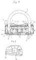
- the U-lock shown in Fig. 1 is conventional Constructed and has a lockable in a lock body 1, U-shaped bow 2, which on its two legs 3, 4 each has a bolt receptacle 5, 6, in which locking elements 7, 8 in the illustrated locking position of the lock intervention.
- the locking elements 7, 8 are by an actuating mechanism in a perpendicular to the longitudinal axis of the stirrup legs 3, 4 extending direction can be acted upon, said operating mechanism is moved via a lock cylinder 9.
- the lock body 1 has two locking block receptacles 10, 11, in which each a bracket leg 3, 4 with its front end first can be introduced. In the locking position shown in Fig. 1 are the both bracket legs 3, 4 completely in the locking block receptacles 10, 11 inserted, and the lock is due to the engagement of the locking elements 7, 8 locked in the bolt receptacles 5, 6.
- the two ends of the stirrup legs 3, 4 each have their own tapered conical element 12 at the front ends, 13 on, to which two cylindrical extensions 14, 15 are connected their, the frustoconical elements 12, 13 opposite Ends are chamfered.
- the attachment of the cushion elements 18, 19 in the cavities 16, 17 can, for example, simply be caused thereby be that the cushion elements 18, 19 in compressed form in the Cavities 16, 17 are "shot in”, whereupon the upholstery elements 18, 19 then by their expansion in the cavities 16, 17 Clamp.
- the cushion elements 18, 19 are positioned so that they are completely in the Lock body 1 locked bracket 2 through the front ends of the cylindrical Extensions 14, 15 in the direction of the longitudinal axis of the stirrup legs 3, 4 are compressed so that ultimately the cushion elements 18, 19th in the manner already described in the unlocked position of the Exercise bracket 2 acting prestressing force on the bracket legs 3, 4 to to prevent the lock from rattling in the event of vibrations.
- FIG. 2 The detail view of FIG. 2 can be seen that the elasticity the cushion element 19 is chosen such that it is complete in the locking bolt receptacle 11 inserted bracket leg 4 to the Form of the cylindrical extension 15 hugs form-fitting, so that play of the stirrup leg 4 perpendicular to its longitudinal axis is also avoided becomes.
- FIGS. 3 and 4 show the lock according to FIGS. 1 and 2 shortly after the bracket 2 has been unlocked from the lock body 1. Because the elasticity of the Upholstery elements 18, 19 selected in the illustrated embodiment is that the cushion elements 18, 19 after permanent compression, after locking the Castle, only slowly return to their relaxed starting position, have the cushion elements 18, 19 according to FIGS. 3 and 4 essentially still the same, adapted to the cylindrical extensions 14, 15 Shape as in FIGS. 1 and 2, which in addition to those already explained above Advantages leads.
Landscapes
- Vibration Dampers (AREA)
- Details Of Connecting Devices For Male And Female Coupling (AREA)
- Connection Of Plates (AREA)
- Mattresses And Other Support Structures For Chairs And Beds (AREA)
- Flexible Shafts (AREA)
- Endoscopes (AREA)
- Supporting Of Heads In Record-Carrier Devices (AREA)
- Mechanical Operated Clutches (AREA)
Abstract
Description
- Fig. 1
- eine Seitenansicht eines erfindungsgemäßen Klobenschlosses in seiner Verriegelungsstellung, wobei ein Bügel des Klobenschlosses in Seitenansicht und der Schloßkörper in einer Schnittansicht dargestellt sind,
- Fig. 2
- eine geschnittene Detailansicht des mit X gekennzeichneten Bereichs gemäß Fig. 1,
- Fig. 3
- eine Darstellung gemäß Fig. 1 mit in Öffnungsstellung befindlichem Bügel, und
- Fig. 4
- eine geschnittene Detailansicht des mit X gekennzeichneten Bereichs gemäß Fig. 3.
- 1
- Schloßkörper
- 2
- Bügel
- 3
- Bügelschenkel
- 4
- Bügelschenkel
- 5
- Riegelaufnahme
- 6
- Riegelaufnahme
- 7
- Verriegelungselement
- 8
- Verriegelungselement
- 9
- Schließzylinder
- 10
- Schließklobenaufnahme
- 11
- Schließklobenaufnahme
- 12
- kegelstumpfförmiges Element
- 13
- kegelstumpfförmiges Element
- 14
- zylindrischer Fortsatz
- 15
- zylindrischer Fortsatz
- 16
- Hohlraum
- 17
- Hohlraum
- 18
- Polsterelement
- 19
- Polsterelement
Claims (17)
- Klobenschloß, insbesondere Bügel- oder Kabelschloß mit einem in einer Schließklobenaufnahme (10, 11) eines Schloßkörpers (1) verriegelbaren Schließkloben (3, 4),
dadurch gekennzeichnet,
daß der Schließkloben (3, 4) über seine Stirnseite im verriegelten Zustand des Schlosses von einem Polsterelement (18, 19) in Richtung seiner Entriegelungsstellung unter Vorspannung gesetzt ist. - Klobenschloß nach Anspruch 1,
dadurch gekennzeichnet,
daß das Polsterelement (18, 19) aus Schaumstoff, insbesondere aus feinporigem Polyurethanschaumstoff, besteht. - Klobenschloß nach einem der vorhergehenden Ansprüche,
dadurch gekennzeichnet,
daß die Elastizität des Polsterelements (18, 19) derart gewählt ist, daß es nach dauerhafter oder langsamer, insbesondere innerhalb von mehr als 0,1 s erfolgender Kompression nur langsam, insbesondere innerhalb von mehr als 20 s, vorzugsweise mehr als 60 s, in seinen entspannten Zustand zurückkehrt. - Klobenschloß nach einem der vorhergehenden Ansprüche,
dadurch gekennzeichnet,
daß die Elastizität des Polsterelements (18, 19) derart gewählt ist, daß es nach schneller oder schlagartiger, insbesondere innerhalb von weniger als 0,1 s erfolgender Kompression schnell, insbesondere innerhalb von weniger als 0,2 s, vorzugsweise weniger als 0,1 s, in seinen entspannten Zustand zurückkehrt. - Klobenschloß nach Anspruch 5,
dadurch gekennzeichnet,
daß das Polsterelement (18, 19) nach schneller oder schlagartiger, insbesondere innerhalb von weniger als 0,1 s erfolgender Kompression zumindest annähernd die Wirkung einer Feder besitzt. - Klobenschloß nach einem der vorhergehenden Ansprüche,
dadurch gekennzeichnet,
daß das Polsterelement (18, 19) aus einem stark kompressiblen Schaumstoff besteht. - Klobenschloß nach Anspruch 6,
dadurch gekennzeichnet,
daß das Polsterelement (18, 19) unter manueller Krafteinwirkung auf weniger als 20 % seines entspannten Volumens komprimierbar ist. - Klobenschloß nach einem der vorhergehenden Ansprüche,
dadurch gekennzeichnet,
daß das Polsterelement (18, 19) mit geringer Kraft, insbesondere mit einer Kraft von 0,2 N bis 5 N, insbesondere 1 N bis 2 N komprimierbar ist. - Klobenschloß nach einem der vorhergehenden Ansprüche,
dadurch gekennzeichnet,
daß die Elastizität des Polsterelements (18, 19) derart gewählt ist, daß es sich im verriegelten Zustand des Schlosses formschlüssig an die Stirnseite und insbesondere auch an an die Stirnseite angrenzende Mantelbereiche des Schließklobens (3, 4) anlegt. - Klobenschloß nach einem der vorhergehenden Ansprüche,
dadurch gekennzeichnet,
daß das Polsterelement (18, 19) am Boden der Schließklobenaufnahme (10, 11) im Schloßkörper (1) fixiert ist. - Klobenschloß nach Anspruch 10,
dadurch gekennzeichnet,
daß die Fixierung zumindest durch eine elastische Klemmung des bereichsweise komprimierten Polsterelements (18, 19) zwischen an die komprimierten Bereiche angrenzenden Bauteilen des Schloßkörpers realisiert ist. - Klobenschloß nach einem der vorhergehenden Ansprüche,
dadurch gekennzeichnet,
daß der Schließkloben (3, 4) mit einem vom stirnseitigen Ende des Schließklobens (3, 4) sowie von einer Riegelaufnahme (5, 6) beabstandeten Anschlagelement versehen ist, welches im verriegelten Zustand des Schlosses an eine Anschlagfläche des Schloßkörpers (1) angrenzt. - Klobenschloß nach Anspruch 12,
dadurch gekennzeichnet,
daß das Anschlagelement als im verriegeltem Zustand des Schlosses zumindest bereichsweise außerhalb der Schließklobenaufnahme (10, 11) zu liegen kommende Hülse ausgebildet ist. - Klobenschloß nach einem der Ansprüche 12 oder 13,
dadurch gekennzeichnet,
daß die Umrandung der Schließklobenaufnahme (10, 11) als Anschlagfläche für das Anschlagelement oder die Hülse ausgebildet ist. - Klobenschloß nach einem der Ansprüche 12 bis 14,
dadurch gekennzeichnet,
daß die Hülse in Axialrichtung des Schließklobens (3, 4) verstellbar an diesem angeordnet ist. - Klobenschloß nach einem der vorherigen Ansprüche,
dadurch gekennzeichnet,
daß beide Bügelenden bzw. Schließkloben (3, 4) eines Bügelschlosses über ihre Stirnseiten im verriegelten Zustand des Schlosses von je einem Polsterelement (18, 19) in Richtung ihrer Entriegelungsstellung unter Vorspannung gesetzt ist. - Klobenschloß nach einem der vorherigen Ansprüche,
dadurch gekennzeichnet,
daß beide Bügelenden (3, 4) eines Bügelschlosses mit je einer Hülse nach einem der Ansprüche 13 bis 15 versehen sind.
Applications Claiming Priority (2)
| Application Number | Priority Date | Filing Date | Title |
|---|---|---|---|
| DE10004602A DE10004602A1 (de) | 2000-02-03 | 2000-02-03 | Klobenschloß |
| DE10004602 | 2000-02-03 |
Publications (3)
| Publication Number | Publication Date |
|---|---|
| EP1122386A2 true EP1122386A2 (de) | 2001-08-08 |
| EP1122386A3 EP1122386A3 (de) | 2001-10-17 |
| EP1122386B1 EP1122386B1 (de) | 2003-12-10 |
Family
ID=7629615
Family Applications (1)
| Application Number | Title | Priority Date | Filing Date |
|---|---|---|---|
| EP01101978A Expired - Lifetime EP1122386B1 (de) | 2000-02-03 | 2001-01-29 | Klobenschloss |
Country Status (5)
| Country | Link |
|---|---|
| US (1) | US20010022097A1 (de) |
| EP (1) | EP1122386B1 (de) |
| AT (1) | ATE256235T1 (de) |
| DE (2) | DE10004602A1 (de) |
| ES (1) | ES2207570T3 (de) |
Families Citing this family (3)
| Publication number | Priority date | Publication date | Assignee | Title |
|---|---|---|---|---|
| WO2008137575A1 (en) * | 2007-05-03 | 2008-11-13 | Jonathon Hocut | Bump resistant pin tumbler lock |
| US7921682B1 (en) * | 2009-12-15 | 2011-04-12 | Jieh-Jung Chang | Padlock with alarm function |
| ES2859999T3 (es) | 2018-04-03 | 2021-10-04 | Knox Ass Inc Dba Knox Company | Protector y absorbedor de fluidos para dispositivos de bloqueo |
Family Cites Families (6)
| Publication number | Priority date | Publication date | Assignee | Title |
|---|---|---|---|---|
| EP0550412A3 (de) * | 1988-05-06 | 1993-07-28 | Aug. Winkhaus GmbH & Co. KG | Langbügelschloss |
| US5394712A (en) * | 1994-01-11 | 1995-03-07 | Nigostar Industry Co., Ltd. | Motorcycle lock |
| US5440904A (en) * | 1994-06-27 | 1995-08-15 | Su; Shun-Chang | Cable lock assembly for bicycles |
| CA2161390C (en) * | 1995-10-25 | 1999-08-10 | Ludwig Piron | Locking device |
| DE19639684A1 (de) * | 1996-09-26 | 1998-04-02 | Winkhaus Fa August | Halterungseinrichtung zur Halterung eines Bügelschlosses |
| DE29618579U1 (de) * | 1996-10-24 | 1996-12-05 | Hsieh, Chen-Kuei, Chung Li, Taoyuan | U-Förmiges Hängeschloss |
-
2000
- 2000-02-03 DE DE10004602A patent/DE10004602A1/de not_active Withdrawn
-
2001
- 2001-01-29 DE DE50101097T patent/DE50101097D1/de not_active Expired - Lifetime
- 2001-01-29 AT AT01101978T patent/ATE256235T1/de not_active IP Right Cessation
- 2001-01-29 ES ES01101978T patent/ES2207570T3/es not_active Expired - Lifetime
- 2001-01-29 EP EP01101978A patent/EP1122386B1/de not_active Expired - Lifetime
- 2001-02-02 US US09/777,006 patent/US20010022097A1/en not_active Abandoned
Also Published As
| Publication number | Publication date |
|---|---|
| DE10004602A1 (de) | 2001-08-09 |
| US20010022097A1 (en) | 2001-09-20 |
| ATE256235T1 (de) | 2003-12-15 |
| EP1122386A3 (de) | 2001-10-17 |
| ES2207570T3 (es) | 2004-06-01 |
| EP1122386B1 (de) | 2003-12-10 |
| DE50101097D1 (de) | 2004-01-22 |
Similar Documents
| Publication | Publication Date | Title |
|---|---|---|
| EP1818563B1 (de) | Arretierbares Kolben-Zylinder-Aggregat | |
| EP1035286A2 (de) | Sicherheitsverriegelung, insbesondere für Türen in Einbauten von Wohnmobilen | |
| DE29700908U1 (de) | Gurtschloß mit Befestigungsbeschlag | |
| DE10228580A1 (de) | Träger für ein Fahrzeug | |
| EP1767808B1 (de) | Federsystem | |
| DE102017112766A1 (de) | Halterung für ein Zweirad-Schloss | |
| DE69030325T2 (de) | Positionierungseinrichtung | |
| DE3223778C2 (de) | ||
| DE10014675A1 (de) | Störungsdämpfer und Gehäuse für einen Störungsdämpfer | |
| DE60115864T2 (de) | Zylinderschlossanordnung | |
| DE202007011066U1 (de) | Sicherheitsgurtschloss | |
| EP1122386B1 (de) | Klobenschloss | |
| DE2916559A1 (de) | Lenkwellen-verriegelungsvorrichtung | |
| WO1991017678A1 (de) | Schocksicherer sicherheitsgurtverschluss | |
| DE10329997B4 (de) | Gleitschutzstift | |
| EP0831198B1 (de) | Bügelschloss | |
| DE2720603A1 (de) | Kopfstuetze fuer kraftfahrzeugsitze | |
| DE3120892C2 (de) | ||
| DE10142278A1 (de) | Bügelschloss, insbesondere Fahrradbügelschloss | |
| EP0641909B1 (de) | Langbügelschloss, mit selbsthemmender Verklemmung eines Riegelelements | |
| DE10343928B3 (de) | Ausstellfeder | |
| DE4405346C2 (de) | Vorrichtung zur Entriegelung und Verriegelung der Rücksitzlehne von Kfz | |
| DE69401294T2 (de) | Einrichtung zur Befestigung eines Schlosses in seinem Gehäuse | |
| DE69403344T2 (de) | Verbesserungen an oder betreffend lenksäulen in fahrzeugen | |
| EP0943487A2 (de) | Vorrichtung zum lösbaren Verbinden mit einem Bügel |
Legal Events
| Date | Code | Title | Description |
|---|---|---|---|
| PUAI | Public reference made under article 153(3) epc to a published international application that has entered the european phase |
Free format text: ORIGINAL CODE: 0009012 |
|
| AK | Designated contracting states |
Kind code of ref document: A2 Designated state(s): AT BE CH CY DE DK ES FI FR GB GR IE IT LI LU MC NL PT SE TR |
|
| AX | Request for extension of the european patent |
Free format text: AL;LT;LV;MK;RO;SI |
|
| PUAL | Search report despatched |
Free format text: ORIGINAL CODE: 0009013 |
|
| AK | Designated contracting states |
Kind code of ref document: A3 Designated state(s): AT BE CH CY DE DK ES FI FR GB GR IE IT LI LU MC NL PT SE TR |
|
| AX | Request for extension of the european patent |
Free format text: AL;LT;LV;MK;RO;SI |
|
| 17P | Request for examination filed |
Effective date: 20011107 |
|
| 17Q | First examination report despatched |
Effective date: 20020227 |
|
| AKX | Designation fees paid |
Free format text: AT BE CH CY DE DK ES FI FR GB GR IE IT LI LU MC NL PT SE TR |
|
| GRAH | Despatch of communication of intention to grant a patent |
Free format text: ORIGINAL CODE: EPIDOS IGRA |
|
| GRAS | Grant fee paid |
Free format text: ORIGINAL CODE: EPIDOSNIGR3 |
|
| GRAA | (expected) grant |
Free format text: ORIGINAL CODE: 0009210 |
|
| AK | Designated contracting states |
Kind code of ref document: B1 Designated state(s): AT BE CH CY DE DK ES FI FR GB GR IE IT LI LU MC NL PT SE TR |
|
| PG25 | Lapsed in a contracting state [announced via postgrant information from national office to epo] |
Ref country code: IE Free format text: LAPSE BECAUSE OF FAILURE TO SUBMIT A TRANSLATION OF THE DESCRIPTION OR TO PAY THE FEE WITHIN THE PRESCRIBED TIME-LIMIT Effective date: 20031210 Ref country code: TR Free format text: LAPSE BECAUSE OF FAILURE TO SUBMIT A TRANSLATION OF THE DESCRIPTION OR TO PAY THE FEE WITHIN THE PRESCRIBED TIME-LIMIT Effective date: 20031210 Ref country code: FI Free format text: LAPSE BECAUSE OF FAILURE TO SUBMIT A TRANSLATION OF THE DESCRIPTION OR TO PAY THE FEE WITHIN THE PRESCRIBED TIME-LIMIT Effective date: 20031210 Ref country code: CY Free format text: LAPSE BECAUSE OF FAILURE TO SUBMIT A TRANSLATION OF THE DESCRIPTION OR TO PAY THE FEE WITHIN THE PRESCRIBED TIME-LIMIT Effective date: 20031210 |
|
| REG | Reference to a national code |
Ref country code: GB Ref legal event code: FG4D Free format text: NOT ENGLISH |
|
| REG | Reference to a national code |
Ref country code: CH Ref legal event code: EP |
|
| REG | Reference to a national code |
Ref country code: IE Ref legal event code: FG4D Free format text: GERMAN |
|
| REF | Corresponds to: |
Ref document number: 50101097 Country of ref document: DE Date of ref document: 20040122 Kind code of ref document: P |
|
| PGFP | Annual fee paid to national office [announced via postgrant information from national office to epo] |
Ref country code: LU Payment date: 20040126 Year of fee payment: 4 |
|
| PGFP | Annual fee paid to national office [announced via postgrant information from national office to epo] |
Ref country code: BE Payment date: 20040127 Year of fee payment: 4 |
|
| PG25 | Lapsed in a contracting state [announced via postgrant information from national office to epo] |
Ref country code: AT Free format text: LAPSE BECAUSE OF NON-PAYMENT OF DUE FEES Effective date: 20040129 |
|
| PGFP | Annual fee paid to national office [announced via postgrant information from national office to epo] |
Ref country code: ES Payment date: 20040129 Year of fee payment: 4 |
|
| PG25 | Lapsed in a contracting state [announced via postgrant information from national office to epo] |
Ref country code: MC Free format text: LAPSE BECAUSE OF NON-PAYMENT OF DUE FEES Effective date: 20040131 |
|
| PG25 | Lapsed in a contracting state [announced via postgrant information from national office to epo] |
Ref country code: DK Free format text: LAPSE BECAUSE OF FAILURE TO SUBMIT A TRANSLATION OF THE DESCRIPTION OR TO PAY THE FEE WITHIN THE PRESCRIBED TIME-LIMIT Effective date: 20040310 Ref country code: GR Free format text: LAPSE BECAUSE OF FAILURE TO SUBMIT A TRANSLATION OF THE DESCRIPTION OR TO PAY THE FEE WITHIN THE PRESCRIBED TIME-LIMIT Effective date: 20040310 |
|
| REG | Reference to a national code |
Ref country code: SE Ref legal event code: TRGR |
|
| GBT | Gb: translation of ep patent filed (gb section 77(6)(a)/1977) |
Effective date: 20040310 |
|
| REG | Reference to a national code |
Ref country code: ES Ref legal event code: FG2A Ref document number: 2207570 Country of ref document: ES Kind code of ref document: T3 |
|
| ET | Fr: translation filed | ||
| REG | Reference to a national code |
Ref country code: IE Ref legal event code: FD4D |
|
| PLBE | No opposition filed within time limit |
Free format text: ORIGINAL CODE: 0009261 |
|
| STAA | Information on the status of an ep patent application or granted ep patent |
Free format text: STATUS: NO OPPOSITION FILED WITHIN TIME LIMIT |
|
| 26N | No opposition filed |
Effective date: 20040913 |
|
| PG25 | Lapsed in a contracting state [announced via postgrant information from national office to epo] |
Ref country code: IT Free format text: LAPSE BECAUSE OF NON-PAYMENT OF DUE FEES Effective date: 20050129 Ref country code: LU Free format text: LAPSE BECAUSE OF NON-PAYMENT OF DUE FEES Effective date: 20050129 |
|
| PG25 | Lapsed in a contracting state [announced via postgrant information from national office to epo] |
Ref country code: LI Free format text: LAPSE BECAUSE OF NON-PAYMENT OF DUE FEES Effective date: 20050131 Ref country code: ES Free format text: LAPSE BECAUSE OF NON-PAYMENT OF DUE FEES Effective date: 20050131 Ref country code: BE Free format text: LAPSE BECAUSE OF NON-PAYMENT OF DUE FEES Effective date: 20050131 Ref country code: CH Free format text: LAPSE BECAUSE OF NON-PAYMENT OF DUE FEES Effective date: 20050131 |
|
| BERE | Be: lapsed |
Owner name: *ABUS AUGUST BREMICKER SOHNE K.G. Effective date: 20050131 |
|
| PG25 | Lapsed in a contracting state [announced via postgrant information from national office to epo] |
Ref country code: NL Free format text: LAPSE BECAUSE OF NON-PAYMENT OF DUE FEES Effective date: 20050801 |
|
| REG | Reference to a national code |
Ref country code: CH Ref legal event code: PL |
|
| NLV4 | Nl: lapsed or anulled due to non-payment of the annual fee |
Effective date: 20050801 |
|
| REG | Reference to a national code |
Ref country code: ES Ref legal event code: FD2A Effective date: 20050131 |
|
| BERE | Be: lapsed |
Owner name: *ABUS AUGUST BREMICKER SOHNE K.G. Effective date: 20050131 |
|
| PG25 | Lapsed in a contracting state [announced via postgrant information from national office to epo] |
Ref country code: PT Free format text: LAPSE BECAUSE OF NON-PAYMENT OF DUE FEES Effective date: 20040510 |
|
| REG | Reference to a national code |
Ref country code: FR Ref legal event code: PLFP Year of fee payment: 16 |
|
| REG | Reference to a national code |
Ref country code: FR Ref legal event code: PLFP Year of fee payment: 17 |
|
| PGFP | Annual fee paid to national office [announced via postgrant information from national office to epo] |
Ref country code: FR Payment date: 20170120 Year of fee payment: 17 Ref country code: SE Payment date: 20170119 Year of fee payment: 17 |
|
| PGFP | Annual fee paid to national office [announced via postgrant information from national office to epo] |
Ref country code: GB Payment date: 20170119 Year of fee payment: 17 |
|
| PGFP | Annual fee paid to national office [announced via postgrant information from national office to epo] |
Ref country code: DE Payment date: 20170330 Year of fee payment: 17 |
|
| REG | Reference to a national code |
Ref country code: DE Ref legal event code: R119 Ref document number: 50101097 Country of ref document: DE |
|
| REG | Reference to a national code |
Ref country code: SE Ref legal event code: EUG |
|
| GBPC | Gb: european patent ceased through non-payment of renewal fee |
Effective date: 20180129 |
|
| PG25 | Lapsed in a contracting state [announced via postgrant information from national office to epo] |
Ref country code: DE Free format text: LAPSE BECAUSE OF NON-PAYMENT OF DUE FEES Effective date: 20180801 Ref country code: FR Free format text: LAPSE BECAUSE OF NON-PAYMENT OF DUE FEES Effective date: 20180131 Ref country code: SE Free format text: LAPSE BECAUSE OF NON-PAYMENT OF DUE FEES Effective date: 20180130 |
|
| REG | Reference to a national code |
Ref country code: FR Ref legal event code: ST Effective date: 20180928 |
|
| PG25 | Lapsed in a contracting state [announced via postgrant information from national office to epo] |
Ref country code: GB Free format text: LAPSE BECAUSE OF NON-PAYMENT OF DUE FEES Effective date: 20180129 |