EP1122167A2 - Schwallschutzplatten für Flüssigkeitstank und Tank mit solchen Ablenkplatten - Google Patents
Schwallschutzplatten für Flüssigkeitstank und Tank mit solchen Ablenkplatten Download PDFInfo
- Publication number
- EP1122167A2 EP1122167A2 EP01200015A EP01200015A EP1122167A2 EP 1122167 A2 EP1122167 A2 EP 1122167A2 EP 01200015 A EP01200015 A EP 01200015A EP 01200015 A EP01200015 A EP 01200015A EP 1122167 A2 EP1122167 A2 EP 1122167A2
- Authority
- EP
- European Patent Office
- Prior art keywords
- baffle
- tank
- attachment portion
- baffles
- slosh
- Prior art date
- Legal status (The legal status is an assumption and is not a legal conclusion. Google has not performed a legal analysis and makes no representation as to the accuracy of the status listed.)
- Granted
Links
- 239000012530 fluid Substances 0.000 claims abstract description 26
- 230000002093 peripheral effect Effects 0.000 claims abstract description 3
- 230000033001 locomotion Effects 0.000 claims description 7
- 239000007788 liquid Substances 0.000 description 10
- 239000000463 material Substances 0.000 description 7
- 239000003380 propellant Substances 0.000 description 6
- 230000001629 suppression Effects 0.000 description 6
- 238000005452 bending Methods 0.000 description 4
- MYMOFIZGZYHOMD-UHFFFAOYSA-N Dioxygen Chemical compound O=O MYMOFIZGZYHOMD-UHFFFAOYSA-N 0.000 description 3
- 230000008901 benefit Effects 0.000 description 3
- 238000013016 damping Methods 0.000 description 3
- 239000000446 fuel Substances 0.000 description 3
- 229910052782 aluminium Inorganic materials 0.000 description 2
- XAGFODPZIPBFFR-UHFFFAOYSA-N aluminium Chemical compound [Al] XAGFODPZIPBFFR-UHFFFAOYSA-N 0.000 description 2
- 230000003466 anti-cipated effect Effects 0.000 description 2
- 229910052751 metal Inorganic materials 0.000 description 2
- 239000002184 metal Substances 0.000 description 2
- 238000012986 modification Methods 0.000 description 2
- 230000004048 modification Effects 0.000 description 2
- 238000005303 weighing Methods 0.000 description 2
- OKTJSMMVPCPJKN-UHFFFAOYSA-N Carbon Chemical compound [C] OKTJSMMVPCPJKN-UHFFFAOYSA-N 0.000 description 1
- 239000004593 Epoxy Substances 0.000 description 1
- 230000001133 acceleration Effects 0.000 description 1
- 230000002411 adverse Effects 0.000 description 1
- 239000002131 composite material Substances 0.000 description 1
- 230000000694 effects Effects 0.000 description 1
- 239000002828 fuel tank Substances 0.000 description 1
- 229910002804 graphite Inorganic materials 0.000 description 1
- 239000010439 graphite Substances 0.000 description 1
- 238000007654 immersion Methods 0.000 description 1
- 238000009434 installation Methods 0.000 description 1
- 230000001788 irregular Effects 0.000 description 1
- 238000004519 manufacturing process Methods 0.000 description 1
- 238000010248 power generation Methods 0.000 description 1
- 230000002787 reinforcement Effects 0.000 description 1
Images



Classifications
-
- B—PERFORMING OPERATIONS; TRANSPORTING
- B65—CONVEYING; PACKING; STORING; HANDLING THIN OR FILAMENTARY MATERIAL
- B65D—CONTAINERS FOR STORAGE OR TRANSPORT OF ARTICLES OR MATERIALS, e.g. BAGS, BARRELS, BOTTLES, BOXES, CANS, CARTONS, CRATES, DRUMS, JARS, TANKS, HOPPERS, FORWARDING CONTAINERS; ACCESSORIES, CLOSURES, OR FITTINGS THEREFOR; PACKAGING ELEMENTS; PACKAGES
- B65D90/00—Component parts, details or accessories for large containers
- B65D90/52—Anti-slosh devices
-
- B—PERFORMING OPERATIONS; TRANSPORTING
- B64—AIRCRAFT; AVIATION; COSMONAUTICS
- B64G—COSMONAUTICS; VEHICLES OR EQUIPMENT THEREFOR
- B64G1/00—Cosmonautic vehicles
- B64G1/22—Parts of, or equipment specially adapted for fitting in or to, cosmonautic vehicles
- B64G1/40—Arrangements or adaptations of propulsion systems
- B64G1/402—Propellant tanks; Feeding propellants
- B64G1/4021—Tank construction; Details thereof
-
- Y—GENERAL TAGGING OF NEW TECHNOLOGICAL DEVELOPMENTS; GENERAL TAGGING OF CROSS-SECTIONAL TECHNOLOGIES SPANNING OVER SEVERAL SECTIONS OF THE IPC; TECHNICAL SUBJECTS COVERED BY FORMER USPC CROSS-REFERENCE ART COLLECTIONS [XRACs] AND DIGESTS
- Y10—TECHNICAL SUBJECTS COVERED BY FORMER USPC
- Y10T—TECHNICAL SUBJECTS COVERED BY FORMER US CLASSIFICATION
- Y10T137/00—Fluid handling
- Y10T137/8593—Systems
- Y10T137/86187—Plural tanks or compartments connected for serial flow
- Y10T137/86212—Plural compartments formed by baffles
Definitions
- the present invention is directed to a baffle for suppressing slosh in a tank containing fluids and a tank for incorporating same.
- Launch vehicles used for space exploration use a large amount of liquid propellant while traveling through the earth's atmosphere and into outer space. Unlike long distance travel for many airplanes, there are no refueling stops or rendezvous with refueling aircraft in mid-flight for space vehicles. Therefore, launch vehicles used for space exploration must carry onboard all fuel necessary for propulsion and power generation for the entire voyage. This requirement means that launch vehicles must be equipped to store hundreds of thousands of pounds of liquid propellant, like liquid oxygen, and handle such propellant efficiently and safely.
- Slosh is caused by tank motions during travel and results in the production of forces that can affect launch vehicle stability and control. If the fluid is allowed to slosh freely in the tank, the moving fluid can have an adverse effect on the flight of the launch vehicle. For example, exciting the fluid above its natural frequency can result in oscillating, pendulum-like forces that can change the stability of the overall dynamic system of the vehicle. As is readily appreciated by those skilled in the art, sloshing fluids can produce forces that cause additional vehicle accelerations that, when responded to by the vehicle control system, form a closed loop that can lead to instability and, ultimately, structural failure. Consequently, the slosh must be suppressed.
- Slosh suppression devices typically are used to damp liquid motions in the tanks of launch vehicles.
- Existing systems for slosh suppression primarily consist of a series of annular ring baffles arranged around the inner wall of the tank. These ring baffles run continuously around the periphery of the inside of the tank and are spaced apart by a given distance. The ring baffles are designed to not flex or bend with the moving fluid.
- Rigid annular ring baffles have been successfully used to suppress slosh in the tank of a launch vehicle.
- ring baffles of this type add more than an insignificant amount of weight to the overall weight of the vehicle.
- the Delta III rocket employs a rigid ring design that weighs approximately 400 pounds.
- the weight devoted to the rigid ring design disadvantageously limits the weight of other items onboard the launch vehicles, such as the payload, the fuel and any other equipment.
- baffle for suppressing slosh in a tank that can sufficiently suppress slosh, while at the same time providing weight, material, and cost savings over ring baffles. It would also be advantageous to provide a tank for incorporating such a baffle.
- the baffle for suppressing slosh in a tank adapted for containing fluids.
- the baffle includes an attachment portion adapted to connect the baffle to an inner sidewall of the tank, and a baffle body extending from the attachment portion and adapted to protrude into the tank.
- the baffle includes a smoothly curved corrugation operably connecting the attachment portion and the baffle body.
- the smoothly curved corrugation operably connecting the attachment portion and the baffle body may be either S-shaped or U-shaped.
- the baffle body is permitted to flex relative to the attachment portion in response to movement of fluid within the tank.
- the baffle body has a proximal edge, a distal edge opposite the proximal edge, and a plurality of ribs extending from the proximal edge to the distal edge.
- the baffle body is advantageously stiffened without unnecessarily increasing its weight.
- the baffle body may be semi-circular in shape.
- the baffle may further include a doubler extending along the attachment portion at an attachment lip.
- the doubler acts to alleviate stress in the attachment portion at attachment holes when the baffle is attached to the inner sidewall of the tank.
- the doubler also can extend outwardly from the attachment portion and into the tank in two tongue-like projections at opposite ends of the doubler in order to provide added reinforcement.
- the tank of the present invention includes a plurality of baffles operably attached to at least one sidewall that at least partially defines an internal cavity for housing fluids.
- the plurality of baffles extend into the internal cavity defined by the at least one sidewall and comprise first and second baffles disposed at first and second heights, respectively, within the tank. Preferably, the first and second heights are different.
- Each baffle extends along only a portion of a perimeter of the at least one sidewall, and the first and second baffles are disposed at different peripheral locations within the tank to further suppress the slosh.
- the plurality of baffles may also be operably connected to each other by a connecting member to ensure that the baffles move in concert.
- an improved baffle is provided to effectively limit slosh within a tank that weighs less than conventional ring baffles.
- the overall weight of the launch vehicle can be advantageously reduced or additional payload or fuel can be carried without increasing the overall weight of the launch vehicle.
- the baffle of the present invention can be designed such that slosh is suppressed as well or better than the suppression provided by ring baffles, even though the overall weight of the baffles is significantly reduced.
- a tank 10 is set forth therein in cross-section in accordance with the present invention.
- Tanks of the present invention can be employed in many applications in which slosh is disadvantageous such as for operation in launch vehicles, and more particularly, for use in launch vehicles designed for space missions.
- the tank shown is cylindrical in shape, although the present invention could be adapted to a differently shaped tank and is not meant to be limited to a cylindrical tank.
- fluid is transported in the tank.
- the fluid commonly is a liquid propellant such as liquid oxygen in which case the tank is a fuel tank, although it should be understood that the present invention is not limited by the type of fluid that may be transported in the tank.
- the tank 10 of the present invention usually includes a plurality of baffles 11 arranged around the periphery of the inside of the tank.
- the plurality of baffles can be sized to effectively damp the slosh characteristics of fluid in any given tank. For example, for a tank that stores liquid oxygen sized approximately 99 inches in radius and 210 inches in length with domed ends, twenty-four semi-circular baffles, each having a radius of approximately thirty inches and weighing approximately six pounds each, are anticipated to effectively suppress slosh within the tank.
- the baffles are mounted at different locations within the tank.
- the plurality of baffles 11 are arranged in longitudinal rows or stacks at evenly-spaced locations around the periphery of the inside of the tank.
- the baffles need not be arranged in stacks, but can be staggered or otherwise positioned in an uneven manner within the tank.
- a plurality of baffles can also be connected so as to move in concert.
- each baffle in a given stack of baffles can be connected together by a connecting member (not shown), such as a rigid tube.
- the rigid tube is formed of a material that is capable of withstanding submersion in liquid, especially liquid propellant, and is compatible with the liquid stored and transported in the tank such that the rigid tube maintains its rigidity while in use.
- the rigid tube is made of hollow extruded aluminum or graphite composite epoxy and is attached to a plurality of the baffles extending into the tank. When connected by the rigid tube, each baffle of a stack moves in concert with the other baffles to which it is attached and acts in unison to suppress the slosh created by the moving fluid in the tank.
- Each baffle is comprised of an attachment portion 13 and a baffle body 14 extending from the attachment portion into the tank.
- the attachment portion 13 is adapted to connect the baffle to an inner sidewall of the tank of the present invention.
- the baffle of the present invention is preferably one continuous member and is made from sheet metal, such as aluminum 7075 of 0.032 inch thickness, although the baffle can be formed of other materials and can have other thicknesses if so desired.
- the tank includes four longitudinal rows or stacks of baffles arranged into equal angular increments, i.e., 90° increments, around the periphery of the inner wall of the tank.
- a tank of the present invention can include different numbers of stacks of baffles spaced at different angular increments, including both even and uneven angular increments, about the periphery of the inner wall of the tank.
- the baffles need not be mounted at the same heights within the tank.
- the tank of one advantageous embodiment includes at least two stacks of baffles with each baffle of a first stack 11a being mounted at a different height than the baffles of the second stack 11b .
- each baffle of the first stack lla can be mounted at a height that is approximately halfway between the respective heights of a pair of baffles of the second stack 11b.
- the baffles can be mounted at other relative heights within the tank without departing from the spirit and scope of the present invention.
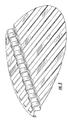
- a baffle 20 of the present invention with a semi-circular shaped baffle body 14.
- the baffle body can have other shapes, if so desired.
- a smoothly curved corrugation 22 formed in the shape of an "S" connects the attachment portion 13 of the baffle 20 to the baffle body 14.
- the purpose of the smoothly curved corrugation 22 is to limit bending of the baffle laterally across the baffle.
- the smoothly curved corrugation 22 can have any shape that allows for flexibility of the baffle while providing stiffening laterally across the baffle.
- the smoothly curved corrugation can be in the shape of a "U.”
- the smoothly curved corrugation 22 can have different sizes and can vary in curvature and still effectively limit bending of the baffle laterally across the baffle while allowing the baffle to flex along the baffle to at least partially suppress slosh within the tank.
- the attachment portion 13 of the baffle is also shown in Figure 4.
- the attachment portion is located opposite the baffle body 14 relative to the corrugation 22 and is adapted so that the baffle 20 can be securely connected to an inner sidewall of the tank.
- the attachment portion 13 comprises an attachment flange or lip 24 fashioned continuously from the material that forms the rest of the baffle.
- the attachment lip 24 is shaped by bending a portion of the baffle that makes up the attachment portion 13 to form a surface substantially perpendicular to the baffle body 14 and substantially corresponding to the shape of the inner wall of the tank.
- the attachment lip 24 of the attachment portion 13 of the baffle 20 can be operably connected to the tank and, more typically, to isogrid nodes.
- Mounting or attachment holes 27 shown in Figure 4, or other suitable apertures can be provided in the attachment lip portion to allow for connection of the baffle to the tank or the isogrid within the tank.
- the baffle can also include a doubler 25 extending along the attachment portion 13 that forms the attachment lip 24 on the inner surface opposite the tank wall, as shown in Figures 3 and 4.
- the doubler 25 is formed to follow the substantially perpendicular surface that comprises the attachment lip 24 .
- the purpose of the doubler 25 is to reinforce the attachment portion 23 of the baffle 20 by alleviating stress along the attachment lip 24 at the attachment holes 27 created when the baffle is operably connected to the inner sidewall of the tank.
- the doubler 25 is most advantageously one continuous piece placed along the attachment lip of the attachment portion and contains suitable apertures for allowing for the baffle to be operably connected to the inner sidewall of the tank.
- the doubler can have any thickness and can be made from any material that is capable of withstanding fatigue during use and that can tolerate immersion in liquid, especially liquid propellant.
- One advantageous embodiment is to make the doubler from the same material and of the same thickness as the remainder of the baffle to which the doubler is attached.
- the doubler can include two tongue-like projections (not shown) located at opposite ends of the doubler that track the bend in the attachment portion and extend outwardly toward the baffle body.
- the baffle of the present invention includes a plurality of ribs 30 formed on the surface of each baffle, as shown in Figure 3.
- the plurality of ribs 30 are added to the baffle to increase bending stiffness, thereby further suppressing slosh in the tank without excessively increasing the weight of the baffle.
- the ribs 30 are generally elevated relative to the remainder of the surface of the baffle and are arranged at substantially evenly spaced intervals on the baffle surface.
- the ribs can be formed at irregular intervals across the surface of the baffle, if so desired.
- the ribs 30 preferably extend from a distal end 28 of the baffle body up to a point proximate to and just short of the point of attachment of the attachment portion 13 to an inner sidewall of the tank.
- each rib extends along the surface of the baffle to a point that is a fraction of an inch from the bend in the attachment portion 13 that forms the attachment lip 24 .
- the proximal end 26 of each rib i.e., the end of the rib proximate the attachment lip 24 , is then chamfered downwardly to the surface of the baffle.
- the ribs 30 can be formed in different manners.
- the baffle body can be stamped to define the ribs extending between proximal and distal ends of the baffle.
- the addition of ribs to the baffle of the present invention allows for a thinner, and therefore lighter, material to be used to form the baffle while not compromising any damping characteristics of the baffle.
- increasing the relative height of each rib above the surface of the baffle acts to increase the baffle stiffness.
- the respective height and spacing of the ribs can be varied to tune the stiffness of the baffle to achieve the desired slosh suppression characteristics for a particular application in a given tank.
- the rigid ring design that is employed by the Delta III rocket that weighs about 400 pounds could be replaced by flexible baffles of the present invention that provide the same slosh suppression while weighing only about 150 pounds, a weight savings of about 250 pounds.
- the baffles of the present invention are also believed to contain less overall parts and be easier to mount within the tank than conventional rigid ring baffles, thereby also saving significantly on installation labor time and cost.
Landscapes
- Engineering & Computer Science (AREA)
- Chemical & Material Sciences (AREA)
- Combustion & Propulsion (AREA)
- Remote Sensing (AREA)
- Aviation & Aerospace Engineering (AREA)
- Mechanical Engineering (AREA)
- Cooling, Air Intake And Gas Exhaust, And Fuel Tank Arrangements In Propulsion Units (AREA)
- Filling Or Discharging Of Gas Storage Vessels (AREA)
Applications Claiming Priority (2)
| Application Number | Priority Date | Filing Date | Title |
|---|---|---|---|
| US497776 | 1995-07-03 | ||
| US09/497,776 US6220287B1 (en) | 2000-02-03 | 2000-02-03 | Baffle for suppressing slosh in a tank and a tank for incorporating same |
Publications (3)
| Publication Number | Publication Date |
|---|---|
| EP1122167A2 true EP1122167A2 (de) | 2001-08-08 |
| EP1122167A3 EP1122167A3 (de) | 2003-01-15 |
| EP1122167B1 EP1122167B1 (de) | 2005-03-23 |
Family
ID=23978257
Family Applications (1)
| Application Number | Title | Priority Date | Filing Date |
|---|---|---|---|
| EP01200015A Expired - Lifetime EP1122167B1 (de) | 2000-02-03 | 2001-01-05 | Schwallschutzplatten für Flüssigkeitstank und Tank mit solchen Ablenkplatten |
Country Status (3)
| Country | Link |
|---|---|
| US (1) | US6220287B1 (de) |
| EP (1) | EP1122167B1 (de) |
| DE (1) | DE60109506T2 (de) |
Cited By (4)
| Publication number | Priority date | Publication date | Assignee | Title |
|---|---|---|---|---|
| DE102008059880A1 (de) * | 2008-12-01 | 2010-07-08 | Mt Aerospace Ag | Behälter zum Aufnehmen, Speichern und Abgeben von Flüssigkeiten und viskosen Stoffen, insbesondere von Kraftstoff oder Treibstoff oder Trinkwasser, und dessen Verwendung |
| KR101691324B1 (ko) * | 2016-03-29 | 2016-12-29 | 주식회사 문창 | 물 출렁임 저감이 가능한 물탱크 |
| CN106969261A (zh) * | 2015-11-20 | 2017-07-21 | 恩凯 | 挡板,包括此的罐及船舶 |
| NL2016531A (en) * | 2016-04-01 | 2017-10-05 | Flax Field Trading B V | A tank container provided with a swash/surge baffle and method for installing such a swash/surge baffle in such a tank container. |
Families Citing this family (66)
| Publication number | Priority date | Publication date | Assignee | Title |
|---|---|---|---|---|
| WO2001083986A2 (en) | 2000-04-28 | 2001-11-08 | Alco Industries, Inc. D/B/A Schroeder Industries | Rotomolded hydraulic reservoir with integral extended length return line |
| US6901941B2 (en) * | 2002-07-10 | 2005-06-07 | Air Products And Chemicals, Inc. | Vessel with optimized purge gas flow and method using same |
| US6568556B1 (en) | 2002-09-23 | 2003-05-27 | Visteon Global Technologies, Inc. | Fuel tank baffle |
| NL1023810C2 (nl) * | 2003-07-03 | 2005-01-04 | Consani Nederland B V | Houder voorzien van tussenschot. |
| WO2006014301A1 (en) * | 2004-07-02 | 2006-02-09 | Exxonmobil Upstream Research Company | Lng sloshing impact reduction system |
| CA2580511C (en) * | 2004-09-16 | 2013-12-31 | Rubbermaid Commercial Products Llc | Mop bucket system with wave reduction capability |
| US7261323B2 (en) * | 2005-03-31 | 2007-08-28 | Nissan Technical Center North America, Inc. | Fuel damper |
| US7445082B2 (en) * | 2005-04-21 | 2008-11-04 | Nifco Inc. | Noise suppressing device and installation structure of same |
| USD532953S1 (en) | 2005-10-14 | 2006-11-28 | Rubbermaid Commercial Products Llc | Dolly for bucket |
| USD536851S1 (en) | 2005-10-14 | 2007-02-13 | Rubbermaid Commercial Products Llc | Bucket |
| USD542992S1 (en) | 2005-10-14 | 2007-05-15 | Rubbermaid Commercial Products Llc | Side press mop wringer |
| USD542494S1 (en) | 2005-10-14 | 2007-05-08 | Rubbermaid Commercial Products Llc | Down press mop wringer |
| USD531772S1 (en) | 2005-10-14 | 2006-11-07 | Rubbermaid Commercial Products Llc | Bucket |
| USD531368S1 (en) | 2005-10-14 | 2006-10-31 | Rubbermaid Commercial Products Llc | Bucket |
| USD531375S1 (en) | 2005-10-14 | 2006-10-31 | Rubbermaid Commercial Products Llc | Dolly for bucket |
| USD530870S1 (en) | 2005-10-14 | 2006-10-24 | Rubbermaid Commercial Products Llc | Bucket |
| US20090013610A1 (en) * | 2006-09-19 | 2009-01-15 | Glynos Peter N | Protective tarp with separate anchors having baffles |
| BE1017840A3 (nl) * | 2007-11-07 | 2009-08-04 | Hool Nv Van | Tussenschot voor een goed reinigbare vloeistoftank voor transportdoeleinden. |
| KR20100056351A (ko) * | 2008-11-18 | 2010-05-27 | 삼성중공업 주식회사 | 슬로싱 억제 장치 |
| TW201043191A (en) * | 2009-06-12 | 2010-12-16 | Univ Chung Yuan Christian | Blood flow simulation system |
| US20110017748A1 (en) * | 2009-07-24 | 2011-01-27 | Ford Global Technologies, Llc | Liquid fuel storage tank for automotive vehicle |
| DE102010032278A1 (de) * | 2010-07-26 | 2012-01-26 | Kautex Textron Gmbh & Co. Kg | Kraftstoffbehälter aus thermoplastischem Kunststoff |
| CA2806122C (en) | 2010-07-30 | 2018-03-27 | Ferus Inc. | Transport tank baffle assembly |
| JP5933713B2 (ja) * | 2011-07-26 | 2016-06-15 | サムスン ヘビー インダストリーズ カンパニー リミテッド | スロッシング抑制装置 |
| US20130160487A1 (en) * | 2011-12-20 | 2013-06-27 | Conocophillips Company | Liquefying natural gas in a motion environment |
| JP5843067B2 (ja) * | 2012-04-10 | 2016-01-13 | 三菱自動車工業株式会社 | 車両用燃料タンク |
| US9260205B2 (en) | 2013-01-15 | 2016-02-16 | The Boeing Company | Antivortex device for multi-outlet liquid reservoir |
| US20150008235A1 (en) * | 2013-07-08 | 2015-01-08 | Esmaeil Khoshsepehr | Apparatus and method to limit slosh and ullage in a liquid container |
| WO2015105961A1 (en) | 2014-01-13 | 2015-07-16 | Embry-Riddle Aeronautical University, Inc. | Floating active baffles, system and method of slosh damping comprising the same |
| ES2685454T3 (es) * | 2014-03-05 | 2018-10-09 | Cytroniq Co., Ltd. | Sistema para controlar la carga de impacto que resulta de un fluido bajo una fuerza interna/externa en un entorno específico |
| US9970389B2 (en) * | 2014-03-06 | 2018-05-15 | The Boeing Company | Antivortex device and method of assembling thereof |
| US10189576B2 (en) | 2014-05-07 | 2019-01-29 | Bae Systems Plc | Liquid storage tank |
| EP2942283A1 (de) * | 2014-05-07 | 2015-11-11 | BAE Systems PLC | Flüssigkeitsspeichersystem |
| WO2015170094A1 (en) | 2014-05-07 | 2015-11-12 | Bae Systems Plc | Liquid storage system |
| GB2528537A (en) | 2014-05-07 | 2016-01-27 | Bae Systems Plc | Liquid storage system |
| EP3140196B1 (de) | 2014-05-07 | 2018-10-17 | BAE Systems PLC | Flüssigkeitsspeichersystem |
| US10640226B2 (en) | 2014-05-07 | 2020-05-05 | Bae Systems Plc | Liquid storage system |
| US10071825B2 (en) * | 2015-01-08 | 2018-09-11 | Embry-Riddle Aeronautical University, Inc. | Hybrid magneto-active propellant management device for active slosh damping within a vehicle fuel tank |
| RU2641022C2 (ru) * | 2016-05-25 | 2018-01-15 | Публичное акционерное общество "Ракетно-космическая корпорация "Энергия" имени С.П. Королёва" | Ракетный разгонный блок |
| KR102451978B1 (ko) * | 2016-12-06 | 2022-10-06 | 현대자동차주식회사 | 자동차용 연료탱크 강성 보강 장치 |
| US20210380925A1 (en) * | 2016-12-09 | 2021-12-09 | Chin-Hsing CHUO | Fermentation tank |
| US11134823B2 (en) | 2017-06-09 | 2021-10-05 | Rubbermaid Commercial Products Llc | Mop buckets and associated methods |
| USD830656S1 (en) | 2017-06-09 | 2018-10-09 | Rubbermaid Commercial Products Llc | Mop bucket |
| USD818234S1 (en) | 2017-06-09 | 2018-05-15 | Rubbermaid Commercial Products Llc | Mop bucket |
| EP3505395A1 (de) * | 2017-12-29 | 2019-07-03 | Tirsan Treyler Sanayi Ve Ticaret Anonim Sirketi | Innovation in einem tankanhängerwellenbrechern |
| US20190323660A1 (en) * | 2018-04-23 | 2019-10-24 | John G. Brothers | Storage tank for cryogenic liquid |
| KR102576431B1 (ko) | 2018-09-10 | 2023-09-08 | 삼성디스플레이 주식회사 | 유기물 제조장치 및 이를 이용한 제조방법 |
| US11396420B2 (en) | 2019-08-09 | 2022-07-26 | Roger Hayes | Tank for transporting liquids |
| KR102275756B1 (ko) * | 2019-10-10 | 2021-07-09 | (주)에이엔에이치스트럭쳐 | 복합재 이너프레임 다중 접합형 배럴 및 이의 제조방법 |
| KR102182478B1 (ko) * | 2019-10-10 | 2020-11-24 | (주)에이엔에이치스트럭쳐 | 복합재 이너프레임 다중 접합형 배럴을 포함하는 외피 일체형 발사체 추진제 탱크 및 이의 제조방법 |
| CN110901955A (zh) * | 2019-12-06 | 2020-03-24 | 上海宇航系统工程研究所 | 框桁式结构的贮箱 |
| FR3110668B3 (fr) * | 2020-05-20 | 2022-04-29 | Air Liquide | Réservoir de stockage de gaz liquéfié. |
| CN112389892A (zh) * | 2020-10-30 | 2021-02-23 | 徐州蓝湖信息科技有限公司 | 一种安全油罐 |
| CN112459925B (zh) * | 2020-11-02 | 2022-03-04 | 中国运载火箭技术研究院 | 一种内置隔板式贮箱 |
| CN112483280B (zh) * | 2020-11-09 | 2023-03-03 | 航天科工火箭技术有限公司 | 一种液体随动防晃装置以及箱体 |
| US11939086B2 (en) * | 2021-02-17 | 2024-03-26 | The Boeing Company | Fuel tanks and reusable launch vehicles comprising these fuel tanks |
| US12059953B2 (en) | 2021-02-17 | 2024-08-13 | The Boeing Company | Composite tanks for reusable launch vehicles and methods of fabricating thereof |
| CN113002295B (zh) * | 2021-04-30 | 2024-06-14 | 合肥丰科汽车部件有限公司 | 一种具有减少液体晃荡功能的铝合金油箱 |
| CN113086445B (zh) * | 2021-05-12 | 2022-02-01 | 南京工业大学 | 一种轻量化复合式防波装置 |
| US12214911B2 (en) * | 2021-08-03 | 2025-02-04 | The Boeing Compnay | Load coupling attachment systems and methods |
| CN115959393A (zh) * | 2021-10-12 | 2023-04-14 | 中集安瑞环科技股份有限公司 | 罐式集装箱、液罐及用于液罐的防波板 |
| US12440845B2 (en) | 2022-04-28 | 2025-10-14 | Elizabeth Deckler | Blood collection tube |
| CN115579159A (zh) * | 2022-09-23 | 2023-01-06 | 中广核研究院有限公司 | 核电用安注箱 |
| US12509240B2 (en) * | 2023-04-11 | 2025-12-30 | General Electric Company | Multi-directional baffles for aircraft fuel tanks |
| WO2025049374A1 (en) * | 2023-08-30 | 2025-03-06 | Rheem Manufacturing Company | Systems and methods for heat pump water heaters with a muffler |
| CN118025684B (zh) * | 2024-04-12 | 2024-06-07 | 山东白燕化工有限公司 | 一种分体式运输罐 |
Family Cites Families (18)
| Publication number | Priority date | Publication date | Assignee | Title |
|---|---|---|---|---|
| US2678660A (en) | 1952-10-31 | 1954-05-18 | Peter J Gurin | Flapper valve for fuel tanks |
| US2860809A (en) * | 1957-02-14 | 1958-11-18 | Skyline Products Inc | Tank baffle |
| US3288186A (en) | 1964-06-05 | 1966-11-29 | Richard T Headrick | Surge damping baffle for liquid storage tank |
| FR1483776A (fr) * | 1966-02-23 | 1967-06-09 | Sodimat | Perfectionnements apportés aux cloisons anti-roulis dans les citernes |
| US3756080A (en) * | 1970-05-11 | 1973-09-04 | Pringle W And Associates Inc | Fuel tank assembly |
| US3653531A (en) * | 1970-06-18 | 1972-04-04 | American Air Filter Co | Storage tank |
| JPS538813A (en) * | 1976-07-13 | 1978-01-26 | Ishikawajima Harima Heavy Ind Co Ltd | Sloshing proof device for cylindrical liquid tank |
| US4214443A (en) | 1978-09-01 | 1980-07-29 | Perkins Engines Limited | Marine engine manifold |
| FR2467235A1 (fr) | 1979-10-12 | 1981-04-17 | Petroles Cie Francaise | Equipement pour la recuperation et le traitement des emulsions petrolieres visqueuses |
| JPS6015552B2 (ja) * | 1980-01-28 | 1985-04-19 | 日本鋼管株式会社 | 円筒貯槽における液面揺動防止装置 |
| US4427045A (en) | 1980-11-28 | 1984-01-24 | Headrick Richard T | Surge dampening baffle for liquid storage tanks |
| DE3641356C1 (de) | 1986-12-03 | 1988-07-07 | Daimler Benz Ag | Kraftstoffbehaelter fuer Fahrzeuge |
| JPH04297329A (ja) * | 1991-03-27 | 1992-10-21 | Nec Ibaraki Ltd | 揺れ防止板付きタンク |
| US5236605A (en) * | 1992-07-07 | 1993-08-17 | Horizontal Rentals, Inc. | Method and apparatus for continuous separation of oil from solid and liquid contaminants |
| JPH09272593A (ja) * | 1996-04-04 | 1997-10-21 | Chiyoda Corp | スロッシング防止装置およびスロッシング防止方法 |
| US5718298A (en) | 1996-04-10 | 1998-02-17 | Rusnak; Jerry A. | Separation system and method for separating the components of a drill bore exhaust mixture |
| US5779092A (en) * | 1996-10-01 | 1998-07-14 | Mega Corporation | Baffle system for tank |
| AU6016899A (en) * | 1998-04-08 | 1999-12-13 | Lockheed Martin Corporation | Anti-slosh liquid propellant tank for launch vehicles |
-
2000
- 2000-02-03 US US09/497,776 patent/US6220287B1/en not_active Expired - Lifetime
-
2001
- 2001-01-05 EP EP01200015A patent/EP1122167B1/de not_active Expired - Lifetime
- 2001-01-05 DE DE60109506T patent/DE60109506T2/de not_active Expired - Lifetime
Non-Patent Citations (3)
| Title |
|---|
| DAVID G. STEPHEN: "Flexible Baffles for Slosh Damping", J. SPACECRAFT, 1965 |
| NASA Space Vehicle Design Criteria Report on Slosh Suppression SP-803, dated May 1969 |
| NASA Technical Note D-694, dated February 1961 |
Cited By (5)
| Publication number | Priority date | Publication date | Assignee | Title |
|---|---|---|---|---|
| DE102008059880A1 (de) * | 2008-12-01 | 2010-07-08 | Mt Aerospace Ag | Behälter zum Aufnehmen, Speichern und Abgeben von Flüssigkeiten und viskosen Stoffen, insbesondere von Kraftstoff oder Treibstoff oder Trinkwasser, und dessen Verwendung |
| DE102008059880B4 (de) * | 2008-12-01 | 2010-10-21 | Mt Aerospace Ag | Behälter zum Aufnehmen, Speichern und Abgeben von Flüssigkeiten und viskosen Stoffen, insbesondere von Kraftstoff oder Treibstoff oder Trinkwasser, und dessen Verwendung |
| CN106969261A (zh) * | 2015-11-20 | 2017-07-21 | 恩凯 | 挡板,包括此的罐及船舶 |
| KR101691324B1 (ko) * | 2016-03-29 | 2016-12-29 | 주식회사 문창 | 물 출렁임 저감이 가능한 물탱크 |
| NL2016531A (en) * | 2016-04-01 | 2017-10-05 | Flax Field Trading B V | A tank container provided with a swash/surge baffle and method for installing such a swash/surge baffle in such a tank container. |
Also Published As
| Publication number | Publication date |
|---|---|
| US6220287B1 (en) | 2001-04-24 |
| EP1122167B1 (de) | 2005-03-23 |
| DE60109506T2 (de) | 2006-02-02 |
| DE60109506D1 (de) | 2005-04-28 |
| EP1122167A3 (de) | 2003-01-15 |
Similar Documents
| Publication | Publication Date | Title |
|---|---|---|
| US6220287B1 (en) | Baffle for suppressing slosh in a tank and a tank for incorporating same | |
| US5845879A (en) | Inflatable conformable fuel tank | |
| US5927651A (en) | Expandable fuel cell | |
| US8181909B2 (en) | Pressure bulkhead for aircraft | |
| US10029848B2 (en) | Flexible liquid transport tank with surge dampening baffles | |
| CA1324598C (en) | Pressurized wall in aircraft | |
| US3645416A (en) | Tank baffle | |
| US2736356A (en) | Expellant bladder type fuel cell | |
| US4046277A (en) | Flexible bottom containers | |
| US6609681B2 (en) | Method and apparatus for damping vibration | |
| US6345788B1 (en) | Composite structure element with built-in damping | |
| US6283412B1 (en) | Anti-slosh liquid propellant tank for launch vehicles | |
| CN114435632A (zh) | 一种能够承载大容量推进剂的卫星动力舱结构 | |
| KR840001547B1 (ko) | 탱크격자 주변에 설치된 유조선의 분리발러스트 | |
| WO2021126031A1 (en) | A suspension assembly for supporting a vibration sensitive device | |
| AU2020264317B2 (en) | Shock absorbing container and vibration isolator system | |
| EP4455017A1 (de) | Kraftstofftank für ein flugzeug, flugzeugrumpf und flugzeug | |
| US6019316A (en) | Device for suspending an aircraft tank | |
| CN217125165U (zh) | 一种能够承载大容量推进剂的卫星动力舱结构 | |
| US4615452A (en) | Compound toroidal tanks | |
| US3110318A (en) | Slosh suppressing device and method | |
| US2844178A (en) | Aircraft jettisonable fuel tank | |
| GB2224000A (en) | Fuselage or pressure vessel structure | |
| JP2010517818A (ja) | フラクタル構造化された支持構造体を有する軽量構造 | |
| CN110641681A (zh) | 用于载具的受压机身的压力舱壁 |
Legal Events
| Date | Code | Title | Description |
|---|---|---|---|
| PUAI | Public reference made under article 153(3) epc to a published international application that has entered the european phase |
Free format text: ORIGINAL CODE: 0009012 |
|
| AK | Designated contracting states |
Kind code of ref document: A2 Designated state(s): AT BE CH CY DE DK ES FI FR GB GR IE IT LI LU MC NL PT SE TR |
|
| AX | Request for extension of the european patent |
Free format text: AL;LT;LV;MK;RO;SI |
|
| RIC1 | Information provided on ipc code assigned before grant |
Free format text: 7B 64G 1/40 A, 7B 60K 15/077 B, 7B 65D 90/52 B, 7F 02K 9/60 B |
|
| PUAL | Search report despatched |
Free format text: ORIGINAL CODE: 0009013 |
|
| AK | Designated contracting states |
Kind code of ref document: A3 Designated state(s): AT BE CH CY DE DK ES FI FR GB GR IE IT LI LU MC NL PT SE TR |
|
| AX | Request for extension of the european patent |
Free format text: AL;LT;LV;MK;RO;SI |
|
| 17P | Request for examination filed |
Effective date: 20030619 |
|
| AKX | Designation fees paid |
Designated state(s): DE FR GB |
|
| 17Q | First examination report despatched |
Effective date: 20030820 |
|
| GRAP | Despatch of communication of intention to grant a patent |
Free format text: ORIGINAL CODE: EPIDOSNIGR1 |
|
| GRAS | Grant fee paid |
Free format text: ORIGINAL CODE: EPIDOSNIGR3 |
|
| GRAA | (expected) grant |
Free format text: ORIGINAL CODE: 0009210 |
|
| AK | Designated contracting states |
Kind code of ref document: B1 Designated state(s): DE FR GB |
|
| REG | Reference to a national code |
Ref country code: GB Ref legal event code: FG4D |
|
| REG | Reference to a national code |
Ref country code: IE Ref legal event code: FG4D |
|
| REF | Corresponds to: |
Ref document number: 60109506 Country of ref document: DE Date of ref document: 20050428 Kind code of ref document: P |
|
| PLBE | No opposition filed within time limit |
Free format text: ORIGINAL CODE: 0009261 |
|
| STAA | Information on the status of an ep patent application or granted ep patent |
Free format text: STATUS: NO OPPOSITION FILED WITHIN TIME LIMIT |
|
| ET | Fr: translation filed | ||
| 26N | No opposition filed |
Effective date: 20051227 |
|
| REG | Reference to a national code |
Ref country code: FR Ref legal event code: PLFP Year of fee payment: 16 |
|
| REG | Reference to a national code |
Ref country code: FR Ref legal event code: PLFP Year of fee payment: 17 |
|
| REG | Reference to a national code |
Ref country code: FR Ref legal event code: PLFP Year of fee payment: 18 |
|
| PGFP | Annual fee paid to national office [announced via postgrant information from national office to epo] |
Ref country code: DE Payment date: 20200129 Year of fee payment: 20 Ref country code: GB Payment date: 20200127 Year of fee payment: 20 |
|
| PGFP | Annual fee paid to national office [announced via postgrant information from national office to epo] |
Ref country code: FR Payment date: 20200127 Year of fee payment: 20 |
|
| REG | Reference to a national code |
Ref country code: DE Ref legal event code: R071 Ref document number: 60109506 Country of ref document: DE |
|
| REG | Reference to a national code |
Ref country code: GB Ref legal event code: PE20 Expiry date: 20210104 |
|
| PG25 | Lapsed in a contracting state [announced via postgrant information from national office to epo] |
Ref country code: GB Free format text: LAPSE BECAUSE OF EXPIRATION OF PROTECTION Effective date: 20210104 |