EP1121520B1 - Kolben für einen verbrennungsmotor - Google Patents
Kolben für einen verbrennungsmotor Download PDFInfo
- Publication number
- EP1121520B1 EP1121520B1 EP99953664A EP99953664A EP1121520B1 EP 1121520 B1 EP1121520 B1 EP 1121520B1 EP 99953664 A EP99953664 A EP 99953664A EP 99953664 A EP99953664 A EP 99953664A EP 1121520 B1 EP1121520 B1 EP 1121520B1
- Authority
- EP
- European Patent Office
- Prior art keywords
- piston
- metal sheet
- piston head
- screw
- sheet
- Prior art date
- Legal status (The legal status is an assumption and is not a legal conclusion. Google has not performed a legal analysis and makes no representation as to the accuracy of the status listed.)
- Expired - Lifetime
Links
- 238000002485 combustion reaction Methods 0.000 title claims description 4
- 239000002184 metal Substances 0.000 claims description 17
- 238000001816 cooling Methods 0.000 claims description 5
- 238000007493 shaping process Methods 0.000 description 2
- 238000013459 approach Methods 0.000 description 1
- 238000003466 welding Methods 0.000 description 1
Images



Classifications
-
- F—MECHANICAL ENGINEERING; LIGHTING; HEATING; WEAPONS; BLASTING
- F02—COMBUSTION ENGINES; HOT-GAS OR COMBUSTION-PRODUCT ENGINE PLANTS
- F02F—CYLINDERS, PISTONS OR CASINGS, FOR COMBUSTION ENGINES; ARRANGEMENTS OF SEALINGS IN COMBUSTION ENGINES
- F02F3/00—Pistons
- F02F3/16—Pistons having cooling means
- F02F3/20—Pistons having cooling means the means being a fluid flowing through or along piston
- F02F3/22—Pistons having cooling means the means being a fluid flowing through or along piston the fluid being liquid
-
- F—MECHANICAL ENGINEERING; LIGHTING; HEATING; WEAPONS; BLASTING
- F01—MACHINES OR ENGINES IN GENERAL; ENGINE PLANTS IN GENERAL; STEAM ENGINES
- F01M—LUBRICATING OF MACHINES OR ENGINES IN GENERAL; LUBRICATING INTERNAL COMBUSTION ENGINES; CRANKCASE VENTILATING
- F01M1/00—Pressure lubrication
- F01M1/08—Lubricating systems characterised by the provision therein of lubricant jetting means
- F01M2001/086—Lubricating systems characterised by the provision therein of lubricant jetting means for lubricating gudgeon pins
Definitions
- the invention relates to a piston for an internal combustion engine according to the preamble of claim 1.
- Piston is e.g. B. from JP-GM 60-125338 known.
- Sheet metal resiliently against the inner hub approaches.
- Such attachment of Sheet metal requires complex shaping of the sheet metal.
- the invention is therefore concerned with the problem of a generic piston for an internal combustion engine the mounting of the sheet on the piston in a simple manner and To achieve wise and without complex shaping of the sheet.
- the grub screw can be used via an Allen key or serration or be turned a slot.
- a pressure piece can also be used, the - with the help of a device - biased Sheet is pushed through an opening in the sheet and that the bias of the when removing the device Sheet metal largely maintained.
- a piston upper part 1 of a pendulum-shaft piston has one Piston plate 2 and an outer cooling channel 3 below it and an inner cold room 4.
- the cooling channel 3 and the Cold room 4 are down through a sheet 5 and 6 respectively limited.
- the sheet is fixed 6 on the upper piston part 1 in that the sheet of one against the piston crown 2 supporting pressure screw 7 pressed down and so against existing on the upper piston part 1 Supports is clamped.
- Connected to the sheet - e.g. B. by pressure welding - is a nut 8, in which the Pressure screw 7 is screwed in.
- the sheet 6 is formed by Lugs 9, which run against the hub support of the piston, secured against twisting.
- the plate 6 is first exactly in the piston positioned and then the sheet is rotated the screw 7 is elastically deformed and preloaded as soon as the screw 7 is supported on the piston crown 2.
- the bracing takes place of the sheet against the piston crown by not tightening a screw or a set screw, but the sheet is pre-tensioned using a tensioning device and then is the pressure piece 7 'by an existing in the sheet Opening pushed through and rotated by 90 °.
- Sheet metal means - in particular further openings - available, which allow the clamping device to grip the sheet metal.
- the pressure piece 7 ' has a round in its upper region Cross-section, in its lower area it is narrow and elongated so that it is a total of a "screwdriver bit" similar.
- the sheet can by a Tilting movement can be positioned in the inner cold room.
Landscapes
- Engineering & Computer Science (AREA)
- Physics & Mathematics (AREA)
- Fluid Mechanics (AREA)
- Chemical & Material Sciences (AREA)
- Combustion & Propulsion (AREA)
- Mechanical Engineering (AREA)
- General Engineering & Computer Science (AREA)
- Pistons, Piston Rings, And Cylinders (AREA)
Description
- Fig. 1
- einen erfindungsgemäßen Kolben im Querschnitt, linke Seite geschnitten in Bolzenrichtung, rechte Seite geschnitten in Druck-Gegendruck-Richtung
- Fig. 2
- einen erfindungsgemäßen Kolben von unten
- Fig. 3
- eine weitere Ausführung des erfindungsgemäßen Kolbens
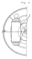
- Fig. 4
- den Kolben gemäß Fig. 3 in einer Ansicht von unten
- Fig. 5
- die Montage des Blechs im inneren Kühlraum des Kolbens.
Claims (4)
- Kolben für einen Verbrennungsmotor mit einem Kolbenboden (2) und mindestens einem unterhalb des Kolbenbodens (2) angeordneten mit Öl beschickbaren Kühlraum (4), dessen obere Begrenzung im Wesentlichen durch den Kolbenboden (2) und dessen untere Begrenzung durch ein am Kolben fixiertes Blech (6) gebildet ist,
dadurch gekennzeichnet, daß auf Druck belastete Mittel das elastisch verformbare Blech (6) in Richtung vom Kolbenboden (2) weg gegen etwa auf Höhe der Nabenabstützung liegende Bereiche des Kolbens drücken. - Kolben nach Anspruch 1,
gekennzeichnet durch die Merkmalezumindest eine Gewindemutter (8) ist an dem Blech (6) fixiertin die Mutter (8) ist als auf Druck belastetes Mittel eine Schraube (7) oder ein Gewindestift eingeschraubt, deren bzw. dessen Ende gegen den Kolbenboden (2) drücktdie sich gegen den Kolbenboden (2) abstützende Schraube (7) bzw. der Gewindestift drückt das Blech (6) nach unten gegen am Kolben angeformte Vorsprünge und verspannt so das Blech (6) gegen den Kolben. - Kolben nach Anspruch 1
gekennzeichnet durch die Merkmalein das Blech (6) ist zur Aufnahme einer als auf Druck belastetes Mittel wirkenden Schraube (7) bzw. eines Gewindestifts eingeschnittendie Schraube (7) bzw. der Gewindestift stützt sich mit ihrem/seinem Ende gegen den Kolbenboden (2) abdie sich gegen den Kolbenboden (2) abstützende Schraube (7) bzw. der Gewindestift drückt das Blech (6) nach unten gegen am Kolben angeformte Vorsprünge und verspannt so das Blech (6) gegen den Kolben. - Kolben nach Anspruch 1,
gekennzeichnet durch die Merkmaledas Blech (6) weist Mittel zum Vorspannen des Blechs (6) mit Hilfe einer Spannvorrichtung auf,das Blech (6) weist eine Öffnung zum Durchschieben eines Druckstückes (7') in Richtung Kolbenboden (2) auf,das Druckstück (7') ist nach dem Durchschieben in eine Position verdrehbar, in der es bei Entfernung der Spannvorrichtung das Blech (6) gegen den Kolbenboden (2) verspannt.
Applications Claiming Priority (3)
| Application Number | Priority Date | Filing Date | Title |
|---|---|---|---|
| DE19846496 | 1998-10-09 | ||
| DE19846496A DE19846496A1 (de) | 1998-10-09 | 1998-10-09 | Kolben für einen Verbrennungsmotor |
| PCT/DE1999/002751 WO2000022289A1 (de) | 1998-10-09 | 1999-08-26 | Kolben für einen verbrennungsmotor |
Publications (2)
| Publication Number | Publication Date |
|---|---|
| EP1121520A1 EP1121520A1 (de) | 2001-08-08 |
| EP1121520B1 true EP1121520B1 (de) | 2002-07-17 |
Family
ID=7883891
Family Applications (1)
| Application Number | Title | Priority Date | Filing Date |
|---|---|---|---|
| EP99953664A Expired - Lifetime EP1121520B1 (de) | 1998-10-09 | 1999-08-26 | Kolben für einen verbrennungsmotor |
Country Status (7)
| Country | Link |
|---|---|
| US (1) | US6453797B1 (de) |
| EP (1) | EP1121520B1 (de) |
| JP (1) | JP4523163B2 (de) |
| KR (1) | KR100628579B1 (de) |
| BR (1) | BR9914389A (de) |
| DE (2) | DE19846496A1 (de) |
| WO (1) | WO2000022289A1 (de) |
Families Citing this family (25)
| Publication number | Priority date | Publication date | Assignee | Title |
|---|---|---|---|---|
| DE19926568A1 (de) * | 1999-06-11 | 2000-12-14 | Mahle Gmbh | Gekühlter Kolben für Verbrennungsmotoren |
| DE10257022A1 (de) * | 2002-12-06 | 2004-06-17 | Mahle Gmbh | Mehrteiliger gekühlter Kolben für einen Verbrennungsmotor |
| US6820582B1 (en) * | 2003-10-06 | 2004-11-23 | Mahle Gmbh | Cooling channel cover for a one-piece piston of an internal combustion engine |
| US6892690B2 (en) * | 2003-10-06 | 2005-05-17 | Mahle Gmbh | Cooling channel cover for a one-piece piston of an internal combustion engine |
| US6920860B2 (en) * | 2003-10-06 | 2005-07-26 | Mahle Gmbh | Cooling channel cover for a one-piece piston of an internal combustion engine |
| USD515590S1 (en) * | 2004-01-13 | 2006-02-21 | Dispenser Services Of Texas, Inc. | Pump valve piston |
| US20060086325A1 (en) * | 2004-10-25 | 2006-04-27 | Ipd, Inc. | Two piece cast ferrous crown piston for internal combustion engine |
| US20060086326A1 (en) * | 2004-10-25 | 2006-04-27 | Ipd, Inc. | One piece cast ferrous crown piston for internal combustion engine |
| DE102005041409A1 (de) * | 2005-09-01 | 2007-03-08 | Mahle International Gmbh | Zweiteiliger Kolben für einen Verbrennungsmotor |
| DE102005042003A1 (de) * | 2005-09-05 | 2007-03-08 | Mahle International Gmbh | Gebauter, flüssigkeitsgekühlter Kolben |
| US20070074695A1 (en) * | 2005-10-04 | 2007-04-05 | Mahle Technology, Inc. | Piston having improved cooling characteristics |
| WO2007068222A1 (de) * | 2005-12-17 | 2007-06-21 | Mahle International Gmbh | Zweiteiliger kolben für einen verbrennungsmotor |
| DE102006027354A1 (de) * | 2006-06-13 | 2007-12-20 | Mahle International Gmbh | Mehrteiliger gekühlter Kolben für einen Verbrennungsmotor |
| DE102007019931A1 (de) * | 2007-04-27 | 2008-10-30 | Mahle International Gmbh | Verfahren zum Verschrauben zweier Metallteile |
| US8347842B2 (en) * | 2008-02-19 | 2013-01-08 | Federal-Mogul Corporation | Coolable piston for internal combustion engine |
| US7762227B2 (en) * | 2008-02-19 | 2010-07-27 | Federal Mogul Corporation | Coolable piston for internal combustion engine |
| US8161934B2 (en) * | 2008-11-05 | 2012-04-24 | Mahle International Gmbh | Multi-part piston for an internal combustion engine and method for its production |
| DE102008055909A1 (de) | 2008-11-05 | 2010-05-06 | Mahle International Gmbh | Mehrteiliger Kolben für einen Verbrennungsmotor |
| DE102008055908A1 (de) * | 2008-11-05 | 2010-05-06 | Mahle International Gmbh | Mehrteiliger Kolben für einen Verbrennungsmotor |
| US20100108001A1 (en) * | 2008-11-05 | 2010-05-06 | Rainer Scharp | Multi-part piston for an internal combustion engine and method for its production |
| US8371261B2 (en) * | 2008-11-05 | 2013-02-12 | Mahle International Gmbh | Multi-part piston for an internal combustion engine and method for its production |
| DE102008055911A1 (de) * | 2008-11-05 | 2010-05-06 | Mahle International Gmbh | Mehrteiliger Kolben für einen Verbrennungsmotor sowie Verfahren zu seiner Herstellung |
| US8146560B2 (en) * | 2008-11-05 | 2012-04-03 | Mahle International Gmbh | Multi-part piston for an internal combustion engine and method for its production |
| DE102009059656B4 (de) | 2009-12-19 | 2019-09-12 | Mahle International Gmbh | Kolben für einen Verbrennungsmotor |
| DE102016225632A1 (de) | 2016-12-20 | 2018-06-21 | Mahle International Gmbh | Kolben einer Brennkraftmaschine |
Family Cites Families (20)
| Publication number | Priority date | Publication date | Assignee | Title |
|---|---|---|---|---|
| US1089823A (en) * | 1912-06-13 | 1914-03-10 | Gen Electric | Piston for internal-combustion engines. |
| GB491843A (en) * | 1937-02-06 | 1938-09-06 | Arthur Villenuve Nicolle | Improvements in and relating to pistons |
| US2214891A (en) * | 1937-08-18 | 1940-09-17 | Oscar G Schrom | Insulated piston |
| DE1040842B (de) * | 1955-08-22 | 1958-10-09 | Ricardo & Co Engineers | Brennkraftmaschinenkolben |
| US3187643A (en) * | 1963-09-24 | 1965-06-08 | Mirrlees Nat Ltd | Pistons for internal combustion engines |
| FR1429327A (fr) * | 1964-12-29 | 1966-02-25 | Hispano Suiza Sa | Perfectionnements apportés aux pistons pour moteurs à combustion interne |
| US3805677A (en) * | 1972-03-01 | 1974-04-23 | Trw Inc | Two-piece oil-cooled piston with thermal expansion control |
| JPS52148740A (en) * | 1976-06-03 | 1977-12-10 | Ito Tetsukoushiyo Kk | Piston crown cooling apparatus for high supercharge four cycle internal combustion engine |
| JPS59188951U (ja) * | 1983-05-31 | 1984-12-14 | 日野自動車株式会社 | 鋳鉄ピストン |
| US4506632A (en) * | 1983-07-28 | 1985-03-26 | Toyota Jidosha Kabushiki Kaisha | Piston assembly with cooling lubricant reservoir defining member engaged to piston pin mounting bosses |
| JPS60125338A (ja) | 1983-12-12 | 1985-07-04 | Hitachi Metals Ltd | 永久磁石合金の製造方法 |
| JPH0545765Y2 (de) * | 1985-09-27 | 1993-11-26 | ||
| EP0237853B1 (de) * | 1986-03-20 | 1991-07-17 | Mahle Gmbh | Mehrteiliger Tauchkolben für Verbrennungsmotoren |
| DE3708377A1 (de) * | 1986-03-20 | 1987-10-01 | Mahle Gmbh | Oelgekuehlter kolben fuer verbrennungsmotoren |
| JPS6322363U (de) * | 1986-07-30 | 1988-02-15 | ||
| JPS6397859A (ja) * | 1986-10-13 | 1988-04-28 | Toyota Motor Corp | 二重天井式ピストン及びその製造方法 |
| DE3643039A1 (de) * | 1986-12-17 | 1988-06-30 | Mahle Gmbh | Kuehlbarer tauchkolben fuer verbrennungsmotoren |
| JPH01141352U (de) * | 1988-03-23 | 1989-09-28 | ||
| GB2261717A (en) * | 1991-11-22 | 1993-05-26 | Ford Motor Co | Piston cooling |
| DE19846152A1 (de) * | 1998-10-07 | 2000-04-13 | Mahle Gmbh | Kolben mit Kolbengrundkörper aus geschmiedetem Stahl und einem Kühlkanal |
-
1998
- 1998-10-09 DE DE19846496A patent/DE19846496A1/de not_active Withdrawn
-
1999
- 1999-08-26 DE DE59902072T patent/DE59902072D1/de not_active Expired - Lifetime
- 1999-08-26 JP JP2000576166A patent/JP4523163B2/ja not_active Expired - Fee Related
- 1999-08-26 US US09/807,044 patent/US6453797B1/en not_active Expired - Lifetime
- 1999-08-26 EP EP99953664A patent/EP1121520B1/de not_active Expired - Lifetime
- 1999-08-26 WO PCT/DE1999/002751 patent/WO2000022289A1/de not_active Ceased
- 1999-08-26 KR KR1020017004450A patent/KR100628579B1/ko not_active Expired - Fee Related
- 1999-08-26 BR BR9914389-5A patent/BR9914389A/pt not_active IP Right Cessation
Also Published As
| Publication number | Publication date |
|---|---|
| EP1121520A1 (de) | 2001-08-08 |
| KR20010087365A (ko) | 2001-09-15 |
| WO2000022289A1 (de) | 2000-04-20 |
| KR100628579B1 (ko) | 2006-09-26 |
| BR9914389A (pt) | 2001-08-07 |
| DE59902072D1 (de) | 2002-08-22 |
| JP4523163B2 (ja) | 2010-08-11 |
| US6453797B1 (en) | 2002-09-24 |
| DE19846496A1 (de) | 2000-04-13 |
| JP2002527665A (ja) | 2002-08-27 |
Similar Documents
| Publication | Publication Date | Title |
|---|---|---|
| WO2000022289A1 (de) | Kolben für einen verbrennungsmotor | |
| DE19628651C2 (de) | Elastische Halterung mit zwei axial zusammengedrückten Elementen | |
| EP1583896B1 (de) | Mehrteiliger gekühlter kolben für einen verbrennungsmotor | |
| DE10018058B4 (de) | Montagehilfe für ein Federbein | |
| DE102005034275B4 (de) | Nockenwellenstellventilvorrichtung | |
| EP0717225B1 (de) | Vorrichtung zur Verbindung von zwei rohrförmigen Leitungsteilen | |
| DE102006004678A1 (de) | Montageeinheit für die Befestigungsöse eines Gurtschlosses | |
| DE10302552A1 (de) | Türfeststeller | |
| DE10216329B4 (de) | Brennkraftmaschine | |
| DE102011104386A1 (de) | Drehverschluss zum Befestigen von Anbauteilen | |
| EP3153725B1 (de) | Verfahren und vorrichtung zur befestigung eines kunststoffbauteils an einem tragenden bauteil | |
| WO1999003713A1 (de) | Befestigungselement sowie ein verfahren zu seiner herstellung | |
| EP2189644B1 (de) | Zweiteiliger Kolben für einen Verbrennungsmotor | |
| EP1464539A2 (de) | Ausrichtvorrichtung für einen Scheinwerfer | |
| DE10128188A1 (de) | Tragbares Arbeitsgerät | |
| DE4224665C2 (de) | Scherblattträger einer Heckenschere | |
| DE20107299U1 (de) | Scheinwerfer mit einem Gehäuse mit Halteklauen | |
| DE19944131B4 (de) | Klemmring | |
| EP1660769A1 (de) | Mehrteiliger kolben f r einen verbrennungsmotor | |
| EP1716026B1 (de) | Scheibenwischvorrichtung | |
| DE102004057559A1 (de) | Kolben für einen Verbrennungsmotor | |
| DE60107178T2 (de) | Elastisches Gelenk für einen Stossdämpfer and Stossdämpfer mit einem solchen Gelenk | |
| DE3442518A1 (de) | Elastisch nachgiebiges lenkergelenk, insbesondere fuer achslenker von nutzfahrzeugen | |
| WO2022243055A1 (de) | Antriebsanordnung | |
| DE3888865T2 (de) | Festwinkelspannteil für Axialventilatorflügel. |
Legal Events
| Date | Code | Title | Description |
|---|---|---|---|
| PUAI | Public reference made under article 153(3) epc to a published international application that has entered the european phase |
Free format text: ORIGINAL CODE: 0009012 |
|
| 17P | Request for examination filed |
Effective date: 20010303 |
|
| AK | Designated contracting states |
Kind code of ref document: A1 Designated state(s): AT BE CH CY DE DK ES FI FR GB GR IE IT LI LU MC NL PT SE |
|
| GRAG | Despatch of communication of intention to grant |
Free format text: ORIGINAL CODE: EPIDOS AGRA |
|
| GRAG | Despatch of communication of intention to grant |
Free format text: ORIGINAL CODE: EPIDOS AGRA |
|
| GRAH | Despatch of communication of intention to grant a patent |
Free format text: ORIGINAL CODE: EPIDOS IGRA |
|
| 17Q | First examination report despatched |
Effective date: 20011219 |
|
| GRAH | Despatch of communication of intention to grant a patent |
Free format text: ORIGINAL CODE: EPIDOS IGRA |
|
| GRAA | (expected) grant |
Free format text: ORIGINAL CODE: 0009210 |
|
| AK | Designated contracting states |
Kind code of ref document: B1 Designated state(s): DE FR GB |
|
| REG | Reference to a national code |
Ref country code: GB Ref legal event code: FG4D Free format text: NOT ENGLISH |
|
| GBT | Gb: translation of ep patent filed (gb section 77(6)(a)/1977) |
Effective date: 20020717 |
|
| REG | Reference to a national code |
Ref country code: IE Ref legal event code: FG4D Free format text: GERMAN |
|
| REF | Corresponds to: |
Ref document number: 59902072 Country of ref document: DE Date of ref document: 20020822 |
|
| ET | Fr: translation filed | ||
| REG | Reference to a national code |
Ref country code: IE Ref legal event code: FD4D Ref document number: 1121520E Country of ref document: IE |
|
| PLBE | No opposition filed within time limit |
Free format text: ORIGINAL CODE: 0009261 |
|
| STAA | Information on the status of an ep patent application or granted ep patent |
Free format text: STATUS: NO OPPOSITION FILED WITHIN TIME LIMIT |
|
| 26N | No opposition filed |
Effective date: 20030422 |
|
| REG | Reference to a national code |
Ref country code: FR Ref legal event code: PLFP Year of fee payment: 17 |
|
| PGFP | Annual fee paid to national office [announced via postgrant information from national office to epo] |
Ref country code: DE Payment date: 20150824 Year of fee payment: 17 Ref country code: GB Payment date: 20150824 Year of fee payment: 17 |
|
| PGFP | Annual fee paid to national office [announced via postgrant information from national office to epo] |
Ref country code: FR Payment date: 20150824 Year of fee payment: 17 |
|
| REG | Reference to a national code |
Ref country code: DE Ref legal event code: R119 Ref document number: 59902072 Country of ref document: DE |
|
| GBPC | Gb: european patent ceased through non-payment of renewal fee |
Effective date: 20160826 |
|
| REG | Reference to a national code |
Ref country code: FR Ref legal event code: ST Effective date: 20170428 |
|
| PG25 | Lapsed in a contracting state [announced via postgrant information from national office to epo] |
Ref country code: GB Free format text: LAPSE BECAUSE OF NON-PAYMENT OF DUE FEES Effective date: 20160826 Ref country code: FR Free format text: LAPSE BECAUSE OF NON-PAYMENT OF DUE FEES Effective date: 20160831 Ref country code: DE Free format text: LAPSE BECAUSE OF NON-PAYMENT OF DUE FEES Effective date: 20170301 |