EP1120361B1 - Method and storage device for temporarily storing a plurality of tire beads - Google Patents
Method and storage device for temporarily storing a plurality of tire beads Download PDFInfo
- Publication number
- EP1120361B1 EP1120361B1 EP01100806A EP01100806A EP1120361B1 EP 1120361 B1 EP1120361 B1 EP 1120361B1 EP 01100806 A EP01100806 A EP 01100806A EP 01100806 A EP01100806 A EP 01100806A EP 1120361 B1 EP1120361 B1 EP 1120361B1
- Authority
- EP
- European Patent Office
- Prior art keywords
- bead
- load
- beads
- unload position
- storage device
- Prior art date
- Legal status (The legal status is an assumption and is not a legal conclusion. Google has not performed a legal analysis and makes no representation as to the accuracy of the status listed.)
- Expired - Lifetime
Links
- 239000011324 bead Substances 0.000 title claims description 108
- 238000000034 method Methods 0.000 title claims description 16
- 230000007246 mechanism Effects 0.000 claims description 45
- 238000004519 manufacturing process Methods 0.000 claims description 12
- 238000001514 detection method Methods 0.000 description 6
- 239000012467 final product Substances 0.000 description 2
- 230000001419 dependent effect Effects 0.000 description 1
- 239000000945 filler Substances 0.000 description 1
- 230000004048 modification Effects 0.000 description 1
- 238000012986 modification Methods 0.000 description 1
Images

Classifications
-
- B—PERFORMING OPERATIONS; TRANSPORTING
- B29—WORKING OF PLASTICS; WORKING OF SUBSTANCES IN A PLASTIC STATE IN GENERAL
- B29D—PRODUCING PARTICULAR ARTICLES FROM PLASTICS OR FROM SUBSTANCES IN A PLASTIC STATE
- B29D30/00—Producing pneumatic or solid tyres or parts thereof
- B29D30/0016—Handling tyres or parts thereof, e.g. supplying, storing, conveying
- B29D2030/0044—Handling tyre beads, e.g., storing, transporting, transferring and supplying to the toroidal support or to the drum
Definitions
- This invention relates to a method and storage device for temporarily storing a plurality of pneumatic tire beads.
- a pneumatic tire generally contains at least two beads.
- a bead is an annular tensile member associated with holding the tire to the wheel rim. After a bead is formed on a bead former, the bead is removed from the former and must be stored until it is built into a tire.
- the device that stores the bead can store a plurality of beads and can be used for transporting the beads to the location in the plant where the beads are to be built into a tire.
- the first device has horizontally extending pins for supporting a plurality of beads.
- the beads hang vertically from the pins.
- this device can store and transport a large number of beads, the use of this device may cause deformation to the beads being stored on it.
- the beads since the beads are hung vertically with support only at the location of the pin, the beads tend to elongate and warp as they hang on the pin. These deformations of the beads cause non-uniformity of the tires built with these elongated and/or warped beads.
- Another problem caused by the use of this device is that automated removal of the beads from the device is difficult. Since the beads are free hanging, automatic removal of the beads requires complex and expensive sensors to detect the exact location of the bead on the pin. Additionally, since some of the beads may stick together on the same pin, separating the beads may cause additional deformities.
- a second device used in the storage and transport of beads is the molded, reusable separator, sometimes referred to as a "tophat" due to its shape.
- a plurality of molded, reusable separators To move a plurality of beads, a plurality of molded, reusable separators must be used. Each separator has a horizontal lip area that extends radially outwardly from the base of a taller crown area. Each bead is placed on the separator so that the crown area of the separator is in the center of the bead and the bead rests on the horizontal lip area. After a bead is placed on a separator, a second separator is placed on top of the first separator. The separators become connected in the crown area such that the lip areas of the separators are vertically separated from each other.
- a second bead is placed on the second separator and the process is continued. Since each separator is sized specifically for a particular bead size, a large inventory of separators is necessary for each different bead size. Since the separators are relatively large, storing the necessary number of separators takes a lot of storage space. Additionally, handling of the separators is difficult due to their bulkiness.
- U.S. Patent 4,614,268 entitled “BEAD TRANSPORTING CONTAINER” discloses another device for storing and transporting beads. This container stores the beads in a vertical position and spaces the beads with separating ribs. The beads are supported by the sidewalls of the container. Each sidewall has a radius of curvature similar to that of the beads.
- EP 0 903 218 discloses an automatic feeder for beads with bead fillers. The beads are hung vertically from two points and are automatically removed to a tire forming machine.
- This invention provides both a method for temporarily storing a plurality of tire beads as claimed in independent claim 1, and a storage device for temporarily storing a plurality of tire beads following independent claim 9. Further embodiments are disclosed in dependent claims.
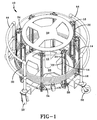
- Fig. 1 shows a view of a storage device 10 for endless, intermediate articles of manufacture on which the method of the invention may be performed.
- An endless, intermediate article of manufacture is an endless component or subassemblies to form a final product. Endless refers to the article having no distinct beginning or ending, such as a ring or hoop.
- An example of an endless, intermediate article of manufacture is a pneumatic tire bead 30, as illustrated.
- the storage device 10 has a frame 12 that supports a plurality of index mechanisms 14.
- Each index mechanism 14 has a first pulley 16, a second pulley 18, and a positive-drive belt 20 that is mounted between the respective pulleys 16, 18.
- the positive-drive belt 20 has an interior surface 22 and an exterior surface 24.
- the interior surface 22 contains timing lugs that interact with grooves in the surface of each pulley 16,18.
- the exterior surface 24 of the positive-drive belt 20 has a plurality of protrusions 26 that extend from the exterior surface 24 for supporting a respective bead 30.
- the device 10 is adaptable for storing other bead sizes.
- the device 10 has at least two mounting plates 3232' that are supported by the frame 12.
- One mounting plate 32 is located near the first pulley 16 of each index mechanism 14.
- a bracket 34 is affixed to the mounting plate 32 and the first pulley 16 is mounted upon this bracket 34.
- a second mounting plate 32' is located near the second pulley 18 of each index mechanism 14.
- Another bracket 34' is affixed to this mounting plate 32' and the second pulley 18 is mounted upon this bracket 34'.
- the respective mounting plates 32, 32' are sized for a range of bead sizes.
- each mounting plate 32, 32' The larger the bead diameter, the larger the size of each mounting plate 32, 32'.
- the index mechanisms 14 are also adjustable upon their respective brackets 34, 34'. This adjustment is made by loosening the index mechanisms 14 on the respective brackets 34, 34' and sliding them to the desired position on the bracket 34, 34'.
- This adjustment is usually limited to a few bead sizes but allows the device 10 to accept a range of bead 30 sizes without requiring a change of the mounting plates 32, 32'.
- Each index mechanism 14 has a load/unload position and a plurality of storage positions. Each respective position is defined by a protrusion 26 on the exterior of the positive-drive belt.
- the load/unload position is located near the second pulley 18 and is the first protrusion that the endless, intermediate article of manufacture rests on when placed on the storage device 10.
- the load/unload position is depicted by the dashed line bead on Fig. 1 and Fig. 4.
- the storage position is any position on the storage device 10 where an endless, intermediate article of manufacture may be stored so that no portion of the bead extends into the load/unload position or can be detected in the load/unload position.
- the positions of each index mechanism 14 are serially movable into or out of the load/unload position.
- An endless, intermediate article of manufacture such as a bead 30, is placed on the device 10 so that it lies in the load/unload position.
- the article is supported by one of the respective protrusions 26 from the positive-drive belt 20 of each index mechanism 14.
- the detection means of a control system detects the presence of the article in the load/unload position and cues the respective index mechanisms 14 to index or move the article out of the load/unload position.
- the respective index mechanisms 14 can be used to move the article a fixed distance away from the load/unload position or can stop the article when its presence is no longer detected in the load/unload position. This movement makes other protrusions 26 available at the load/unload position to receive another article.
- the detection means used by the control system may be a photo eye, a limit switch, or any other means for detecting the presence or lack of presence of the article in the load/unload position.
- the device 10 is used to temporarily store a plurality of endless, intermediate articles of manufacture prior to their being built into a final product.
- An article is loaded onto the device 10 by placing the article, such as a bead 30, in the load/unload position on the device 10, indexing the article out of the load/unload position and into a storage position, and repeating these steps with additional articles until a desired number of articles are placed on the storage device 10.
- the device 10 may be loaded with articles until it is manually stopped or until a second detection means located near the first pulley 16 of the index mechanisms 14 detects the presence of an article indicating that the device 10 is completely loaded. When the device 10 is completely loaded, the control system prevents the further indexing of the articles away from the load/unload position.
- a switch located on the control system is positioned in an unload position. This reverses the direction of movement of the respective index mechanisms 14, as compared to when the device 10 is being loaded.
- the control system indexes the respective index mechanisms 14 toward the load/unload position until an article is positioned in the load/unload position.
- the detection means of the control system determines the presence of the article in the load/unload position. After the article is removed from the load/unload position, either automatically or manually, the detection means indicates to the control system the lack of the presence of an article in the load/unload position.
- the control system then cues the index mechanisms 14 to index an article out of a storage position and into the load/unload position.
- the indexing of the article into the load/unload position can be done by moving the article a fixed distance toward the load unload position and detecting the article in the load/unload position, or by detecting the lack of presence of an article in the load/unload position, moving an article toward the load/unload position, and stopping the article when the presence of the article in the load/unload position is detected. This method can be repeated until it is manually stopped or until the device 10 no longer contains any articles.
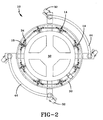
- Fig. 3 is a detailed view of a portion of the device 10 near the first pulley 16 of the respective index mechanisms 14.
- the first pulley 16 is mounted upon a bracket 34 that is affixed to a mounting plate 32.
- the mounting plate 32 and the bracket 34 are not required as the first pulley 16 can be directly attached to the frame 12.
- the mounting plates 32, 32' and brackets 34, 34' are used.
- Fig. 3 also shows the use of a connecting shaft 38 that connects the first pulley 16 of each index mechanism 14. The use of this connecting shaft 38 allows each index mechanism 14 to move at the same speed as the other index mechanisms 14, keeping the respective beads 30 parallel to one another at all times.
- the use of the connecting shaft 38 enables a single drive mechanism 40 to drive all of the index mechanisms 14. Although the device 10 can be used without a connecting shaft 38, such use would require multiple drive mechanisms 40 and a much more complex control system to control the timing of each index mechanism 14.
- the drive mechanism 40 can be electrically, pneumatically, hydraulically, manually or spring operated. Ideally, the drive mechanism is pneumatically operated with limit switches used as the detection means for the control system.
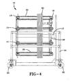
- Fig. 4 shows an embodiment of the device 10 where the index mechanisms 14 move horizontally such that the respective articles are stored and transported in a vertical position.
- the device 10 can be modified so that loading and unloading can take place at opposite ends of the device 10. Such modification would involve changing the location of the frame 12 and most likely supporting the articles from an outside diameter.
- the device 10 can be designed to be able to tilt between the vertical position shown in Fig. 1 and the horizontal position shown in Fig. 4.
- the device 10 may be loaded while in the vertical position and then tilted, changing the orientation of the index mechanisms 14, to the horizontal position prior to unloading, or vice versa.
- the number of index mechanisms 14 can be adjusted depending upon the size of the beads 30 to be stored. Ideally, a device 10 will have a sufficient number of index mechanisms 14 to properly support the bead 30. Proper support prevents the beads 30 from warping or deforming while being stored and transported. Thus, the larger the bead diameter, the more likely additional index mechanisms 14 will be required to properly support the beads 30. Additionally, the spacing between respective protrusions 26 can be varied to accept beads 30 with larger widths or with attached apexes. The index mechanisms 14 may also be placed to support the respective beads 30 by their outside diameter, as opposed to the inside diameter as depicted.
- the frame 12 can be mounted on a plurality of casters 32 or can be mounted on rails having cutouts that are accessible by a forklift or similar device. Multiple devices may be placed on one platform. This platform may have devices for different size beads or multiple devices for one size bead.
- the second pulleys 18 should have a diameter sufficiently small enough to allow the protrusions 26 located near the load/unload position to move out of the way of a respective bead 30 being placed on the device 10.
- the device 10 can also be provided with safety rails 44 to prevent human access into the area of the index mechanisms 14.
- the device 10 can be used to properly support a plurality of endless, intermediate articles of manufacture, such as pneumatic tire beads 30, such that deformations caused during the storage and transportation of the respective articles can be eliminated.
- the device 10 also provides for the loading and the unloading of each article at a set location on the device 10, called the load/unload position, allowing for ease of automation for loading and unloading the articles.
Landscapes
- Engineering & Computer Science (AREA)
- Mechanical Engineering (AREA)
- Tyre Moulding (AREA)
- Storing, Repeated Paying-Out, And Re-Storing Of Elongated Articles (AREA)
- Automatic Assembly (AREA)
- Warehouses Or Storage Devices (AREA)
- Control Of Conveyors (AREA)
Applications Claiming Priority (2)
| Application Number | Priority Date | Filing Date | Title |
|---|---|---|---|
| US09/491,060 US6468016B1 (en) | 2000-01-25 | 2000-01-25 | Method for temporary storage of endless, intermediate articles of manufacture |
| US491060 | 2000-01-25 |
Publications (3)
| Publication Number | Publication Date |
|---|---|
| EP1120361A2 EP1120361A2 (en) | 2001-08-01 |
| EP1120361A3 EP1120361A3 (en) | 2003-03-26 |
| EP1120361B1 true EP1120361B1 (en) | 2006-06-21 |
Family
ID=23950622
Family Applications (1)
| Application Number | Title | Priority Date | Filing Date |
|---|---|---|---|
| EP01100806A Expired - Lifetime EP1120361B1 (en) | 2000-01-25 | 2001-01-15 | Method and storage device for temporarily storing a plurality of tire beads |
Country Status (5)
| Country | Link |
|---|---|
| US (1) | US6468016B1 (enExample) |
| EP (1) | EP1120361B1 (enExample) |
| JP (1) | JP2001247262A (enExample) |
| BR (1) | BR0100083A (enExample) |
| DE (1) | DE60120799T2 (enExample) |
Families Citing this family (7)
| Publication number | Priority date | Publication date | Assignee | Title |
|---|---|---|---|---|
| JP4256281B2 (ja) * | 2004-02-24 | 2009-04-22 | 株式会社ブリヂストン | タイヤの製造方法およびビード部材供給装置 |
| US7393174B2 (en) * | 2004-07-28 | 2008-07-01 | General Electric Company | Field coil handling cart and transfer method |
| DE602005023916D1 (de) | 2005-12-28 | 2010-11-11 | Pirelli | Verfahren und vorrichtung zur herstellung von luftreifen |
| US8794288B2 (en) | 2008-08-21 | 2014-08-05 | Vmi Holland B.V. | Method for transferring and placing beads for tyres, device for carrying out such a method and spacer to be used in such a method and/or device |
| ITMI20122179A1 (it) | 2012-12-19 | 2014-06-20 | Pirelli | Metodo per verificare la corretta formazione dei talloni in un processo e in un impianto per confezionare pneumatici per ruote di veicoli. |
| DE102022210968A1 (de) * | 2022-10-18 | 2024-04-18 | Continental Reifen Deutschland Gmbh | Verfahren zum Fördern von Rohkernen |
| CN117446264A (zh) * | 2023-11-15 | 2024-01-26 | 苏州华卓自动化设备有限公司 | 一种汽车内饰件自动堆叠设备 |
Family Cites Families (18)
| Publication number | Priority date | Publication date | Assignee | Title |
|---|---|---|---|---|
| US2576107A (en) * | 1948-11-05 | 1951-11-27 | John C Davis | Endless conveyer storage system |
| US4018325A (en) * | 1975-10-09 | 1977-04-19 | The Pillsbury Company | Automatic package accumulator |
| JPS5620933U (enExample) * | 1979-07-20 | 1981-02-24 | ||
| US4358170A (en) * | 1979-07-23 | 1982-11-09 | General Battery Corporation | Group storage tower for storing stacks, groups of elements or pasted battery plates in a dust-free manner |
| GB2140376B (en) | 1983-04-26 | 1986-08-06 | Zuerich Verpackungstech | Carrier for a drag chain conveyor for loose articles |
| GB8517771D0 (en) | 1985-07-15 | 1985-08-21 | Black & Decker Inc | Electric motors |
| US4614268A (en) * | 1985-07-31 | 1986-09-30 | The Goodyear Tire & Rubber Company | Bead transporting container |
| US4790719A (en) * | 1985-07-31 | 1988-12-13 | The Goodyear Tire & Rubber Company | Method for storing and feeding tire beads |
| US4683020A (en) * | 1985-07-31 | 1987-07-28 | The Goodyear Tire & Rubber Company | Apparatus for storing and feeding tire beads |
| US4656817A (en) * | 1986-01-10 | 1987-04-14 | Advalloy, Inc. | Apparatus for loading singulated lead frames into containers |
| IT1217766B (it) | 1988-06-02 | 1990-03-30 | Meschi Ind Grafica | Carrello automatico di servizio per muovere o trasportare pacchi di materiale in fogli e suo metodo di funzionamento |
| US5088872A (en) | 1989-10-03 | 1992-02-18 | Kajima Corporation | Automatic equipment for collecting and setting up chairs |
| DE4103993A1 (de) | 1991-02-09 | 1992-08-13 | Otmar Heim | Vorrichtung zum transport von zu be- bzw. verarbeitenden werkstuecken |
| US5244330A (en) * | 1991-08-29 | 1993-09-14 | Custom Metal Designs, Inc. | Bottler loader and method |
| JP3205382B2 (ja) * | 1992-04-27 | 2001-09-04 | 横浜ゴム株式会社 | タイヤビードの移載装置 |
| AU2639595A (en) | 1994-05-12 | 1995-12-05 | Bobby J. Travis | Self-propelled lifting apparatus |
| JPH07309496A (ja) | 1994-05-16 | 1995-11-28 | Riso Kagaku Corp | 印刷機の排紙装置 |
| JP3808603B2 (ja) * | 1997-09-17 | 2006-08-16 | 株式会社ブリヂストン | ビードフィラー付きビードの自動供給装置 |
-
2000
- 2000-01-25 US US09/491,060 patent/US6468016B1/en not_active Expired - Fee Related
-
2001
- 2001-01-15 EP EP01100806A patent/EP1120361B1/en not_active Expired - Lifetime
- 2001-01-15 DE DE60120799T patent/DE60120799T2/de not_active Expired - Fee Related
- 2001-01-16 BR BR0100083-7A patent/BR0100083A/pt active Search and Examination
- 2001-01-24 JP JP2001015957A patent/JP2001247262A/ja active Pending
Also Published As
| Publication number | Publication date |
|---|---|
| EP1120361A3 (en) | 2003-03-26 |
| US6468016B1 (en) | 2002-10-22 |
| JP2001247262A (ja) | 2001-09-11 |
| DE60120799T2 (de) | 2007-06-28 |
| DE60120799D1 (de) | 2006-08-03 |
| EP1120361A2 (en) | 2001-08-01 |
| BR0100083A (pt) | 2001-08-28 |
Similar Documents
| Publication | Publication Date | Title |
|---|---|---|
| US7007793B2 (en) | Container transfer device having a variable geometry guide wheel | |
| EP2328745B1 (en) | Method and device for transferring and placing tyre beads and spacer to be used therefor. | |
| CA2559319C (en) | Process and a device for conveying odd-shaped containers | |
| EP1120361B1 (en) | Method and storage device for temporarily storing a plurality of tire beads | |
| EP0743138A2 (en) | Auto tray changer | |
| WO2016103993A1 (ja) | 物品搬送用容器昇降搬送装置 | |
| CA1236050A (en) | Code sorting and handling system for beaded tires | |
| US6769856B2 (en) | Plant for unloading stacks of thermoformed objects from a receiving cage to a removing conveyer | |
| EP0452159B1 (en) | Parts tray conveying system | |
| EP0162686B1 (en) | Tyre transport jig | |
| US5064330A (en) | Belt-shaped member taking-out and transfer apparatus | |
| JPH082680A (ja) | 箱物品積層方法及び装置 | |
| EP0289469B1 (en) | Machine for vulcanizing tires with devices for collecting and unloading the tire being treated | |
| US5853648A (en) | Cooling of tires at the end of their vulcanization | |
| WO2019210735A1 (zh) | 摆臂式轮胎后处理装置 | |
| EP0468344B1 (en) | Vehicle tire loading-unloading device | |
| CN114616091A (zh) | 轮胎处理装置和方法以及轮胎硫化机 | |
| JPH0772009B2 (ja) | 生タイヤ搬送装置 | |
| EP1749647A1 (en) | Tire bead stretcher and method for holding a green tire | |
| EP0425908A1 (en) | Container for an uncured radial tire | |
| JP4681758B2 (ja) | ファーストカバー搬送装置 | |
| JP7609546B2 (ja) | 容器取出装置およびそれを用いた食品盛付システム | |
| JP2528255B2 (ja) | ホイルへのタイヤ組付装置 | |
| JP2913083B2 (ja) | ベルト装着装置 | |
| CN218173788U (zh) | 一种光学筛选机 |
Legal Events
| Date | Code | Title | Description |
|---|---|---|---|
| PUAI | Public reference made under article 153(3) epc to a published international application that has entered the european phase |
Free format text: ORIGINAL CODE: 0009012 |
|
| AK | Designated contracting states |
Kind code of ref document: A2 Designated state(s): AT BE CH CY DE DK ES FI FR GB GR IE IT LI LU MC NL PT SE TR |
|
| AX | Request for extension of the european patent |
Free format text: AL;LT;LV;MK;RO;SI |
|
| PUAL | Search report despatched |
Free format text: ORIGINAL CODE: 0009013 |
|
| AK | Designated contracting states |
Kind code of ref document: A3 Designated state(s): AT BE CH CY DE DK ES FI FR GB GR IE IT LI LU MC NL PT SE TR |
|
| AX | Request for extension of the european patent |
Extension state: AL LT LV MK RO SI |
|
| RIC1 | Information provided on ipc code assigned before grant |
Ipc: 7B 65G 47/08 B Ipc: 7B 65D 85/04 B Ipc: 7B 29D 30/26 A Ipc: 7B 29D 30/00 B |
|
| 17P | Request for examination filed |
Effective date: 20030926 |
|
| 17Q | First examination report despatched |
Effective date: 20031021 |
|
| AKX | Designation fees paid |
Designated state(s): DE FR GB IT |
|
| GRAP | Despatch of communication of intention to grant a patent |
Free format text: ORIGINAL CODE: EPIDOSNIGR1 |
|
| RTI1 | Title (correction) |
Free format text: METHOD AND STORAGE DEVICE FOR TEMPORARILY STORING A PLURALITY OF TIRE BEADS |
|
| GRAS | Grant fee paid |
Free format text: ORIGINAL CODE: EPIDOSNIGR3 |
|
| GRAA | (expected) grant |
Free format text: ORIGINAL CODE: 0009210 |
|
| AK | Designated contracting states |
Kind code of ref document: B1 Designated state(s): DE FR GB IT |
|
| PG25 | Lapsed in a contracting state [announced via postgrant information from national office to epo] |
Ref country code: IT Free format text: LAPSE BECAUSE OF FAILURE TO SUBMIT A TRANSLATION OF THE DESCRIPTION OR TO PAY THE FEE WITHIN THE PRESCRIBED TIME-LIMIT;WARNING: LAPSES OF ITALIAN PATENTS WITH EFFECTIVE DATE BEFORE 2007 MAY HAVE OCCURRED AT ANY TIME BEFORE 2007. THE CORRECT EFFECTIVE DATE MAY BE DIFFERENT FROM THE ONE RECORDED. Effective date: 20060621 |
|
| REG | Reference to a national code |
Ref country code: GB Ref legal event code: FG4D |
|
| REF | Corresponds to: |
Ref document number: 60120799 Country of ref document: DE Date of ref document: 20060803 Kind code of ref document: P |
|
| ET | Fr: translation filed | ||
| PLBE | No opposition filed within time limit |
Free format text: ORIGINAL CODE: 0009261 |
|
| STAA | Information on the status of an ep patent application or granted ep patent |
Free format text: STATUS: NO OPPOSITION FILED WITHIN TIME LIMIT |
|
| 26N | No opposition filed |
Effective date: 20070322 |
|
| GBPC | Gb: european patent ceased through non-payment of renewal fee |
Effective date: 20070115 |
|
| PG25 | Lapsed in a contracting state [announced via postgrant information from national office to epo] |
Ref country code: GB Free format text: LAPSE BECAUSE OF NON-PAYMENT OF DUE FEES Effective date: 20070115 |
|
| PGFP | Annual fee paid to national office [announced via postgrant information from national office to epo] |
Ref country code: DE Payment date: 20080131 Year of fee payment: 8 Ref country code: IT Payment date: 20080118 Year of fee payment: 8 |
|
| PGFP | Annual fee paid to national office [announced via postgrant information from national office to epo] |
Ref country code: FR Payment date: 20080107 Year of fee payment: 8 |
|
| PG25 | Lapsed in a contracting state [announced via postgrant information from national office to epo] |
Ref country code: DE Free format text: LAPSE BECAUSE OF NON-PAYMENT OF DUE FEES Effective date: 20090801 |
|
| REG | Reference to a national code |
Ref country code: FR Ref legal event code: ST Effective date: 20091030 |
|
| PG25 | Lapsed in a contracting state [announced via postgrant information from national office to epo] |
Ref country code: FR Free format text: LAPSE BECAUSE OF NON-PAYMENT OF DUE FEES Effective date: 20090202 |
|
| PG25 | Lapsed in a contracting state [announced via postgrant information from national office to epo] |
Ref country code: IT Free format text: LAPSE BECAUSE OF NON-PAYMENT OF DUE FEES Effective date: 20090115 |