EP1118739A1 - Schloss - Google Patents
Schloss Download PDFInfo
- Publication number
- EP1118739A1 EP1118739A1 EP00870007A EP00870007A EP1118739A1 EP 1118739 A1 EP1118739 A1 EP 1118739A1 EP 00870007 A EP00870007 A EP 00870007A EP 00870007 A EP00870007 A EP 00870007A EP 1118739 A1 EP1118739 A1 EP 1118739A1
- Authority
- EP
- European Patent Office
- Prior art keywords
- dead bolt
- lock
- bolt
- lever
- pivot
- Prior art date
- Legal status (The legal status is an assumption and is not a legal conclusion. Google has not performed a legal analysis and makes no representation as to the accuracy of the status listed.)
- Granted
Links
Images


Classifications
-
- E—FIXED CONSTRUCTIONS
- E05—LOCKS; KEYS; WINDOW OR DOOR FITTINGS; SAFES
- E05B—LOCKS; ACCESSORIES THEREFOR; HANDCUFFS
- E05B63/00—Locks or fastenings with special structural characteristics
- E05B63/0017—Locks with sliding bolt without provision for latching
- E05B63/0021—Locks with sliding bolt without provision for latching the bolt being shot over an increased length by a single turning operation of the key
-
- E—FIXED CONSTRUCTIONS
- E05—LOCKS; KEYS; WINDOW OR DOOR FITTINGS; SAFES
- E05B—LOCKS; ACCESSORIES THEREFOR; HANDCUFFS
- E05B63/00—Locks or fastenings with special structural characteristics
- E05B63/04—Locks or fastenings with special structural characteristics for alternative use on the right-hand or left-hand side of wings
- E05B63/044—Locks or fastenings with special structural characteristics for alternative use on the right-hand or left-hand side of wings with reversible bolt or bolt head
-
- E—FIXED CONSTRUCTIONS
- E05—LOCKS; KEYS; WINDOW OR DOOR FITTINGS; SAFES
- E05B—LOCKS; ACCESSORIES THEREFOR; HANDCUFFS
- E05B63/00—Locks or fastenings with special structural characteristics
- E05B63/06—Locks or fastenings with special structural characteristics with lengthwise-adjustable bolts ; with adjustable backset, i.e. distance from door edge
-
- E—FIXED CONSTRUCTIONS
- E05—LOCKS; KEYS; WINDOW OR DOOR FITTINGS; SAFES
- E05B—LOCKS; ACCESSORIES THEREFOR; HANDCUFFS
- E05B9/00—Lock casings or latch-mechanism casings ; Fastening locks or fasteners or parts thereof to the wing
- E05B2009/004—Shape of the lock housing
-
- E—FIXED CONSTRUCTIONS
- E05—LOCKS; KEYS; WINDOW OR DOOR FITTINGS; SAFES
- E05B—LOCKS; ACCESSORIES THEREFOR; HANDCUFFS
- E05B59/00—Locks with latches separate from the lock-bolts or with a plurality of latches or lock-bolts
Definitions
- the present invention relates to a lock, in particular a safety lock for outside gates, doors or fences, comprising a frame, a dead bolt slidably mounted in a predetermined direction on the frame between a retracted and a projecting position, a key actuated cylinder provided with a rotary driving bit arranged to move the dead bolt from its retracted to its projecting position and vice versa, and locking means for locking the dead bolt in its retracted and projecting positions.
- Such a lock is disclosed in WO 98/37295 in the name of the present applicant.
- the lock disclosed in this international application is mounted laterally against a tubular profile of the gate or fence wherein holes are made so that the dead and latch bolt can extend right through this profile.
- the dead bolt is provided on its lower side with three different notches wherein the rotary driving bit engages this bolt to move it between its retracted and projecting positions. By selecting one of the three notches, the distance over which the dead bolt projects out of the lock can be adjusted in accordance with the diameter of the tubular profile.
- a disadvantage of the lock disclosed in WO 98/37295 is however that the stroke of the dead lock, or in other words the distance over which the dead lock is moved when going from its projecting position to its retracted position or vice versa, is determined by the length of the rotary driving bit of the cylinder and is thus limited to a certain maximum stroke.
- a so-called Euro profile cylinder according to the standard DIN V 18 254/07.91 a stroke of about 15 mm can thus be achieved. In indoor applications, such a stroke may be enough but in certain outdoor applications, a larger stroke is to be preferred.
- the lock catcher is usually fixed to a pole placed in a hole in the ground.
- the pole may move somewhat, especially after some time under the influence of frost or moisture or when a force is exerted thereon for example by a burglar who tries to force the pole away from the lock. It will be clear that the larger the stroke of the dead bolt, the more difficult it will be to withdraw the dead bolt from the lock catcher by removing the pole from the gate or fence.
- An object of the present invention is therefore to provide a lock with a dead bolt having an increased stroke for one single turn of the key.
- the lock according to the invention is characterised in that said rotary driving bit is arranged to move the dead bolt through the intermediary of a dead bolt lever, which dead bolt lever is pivoted about a pivot with respect to the frame and engages the dead bolt on a first distance from said pivot to move this dead bolt from its retracted to its projecting position or vice versa upon rotation of the dead bolt lever around said pivot, said rotary bit engaging the dead bolt lever on a distance from said pivot smaller than said first distance.
- the rotational motion to the rotary driving bit of the cylinder is converted into the translational motion of the dead bolt through the intermediary of the dead bolt lever. Since the driving bit engages the dead bolt lever on a smaller distance from the pivot of this lever than the distance between this pivot and the location where the lever engages the dead bolt, a lever effect is obtained resulting in a larger displacement of the dead bolt. However, this is not the only possible stroke increasing effect. Indeed, by the rotational motion of the dead bolt lever around its pivot, the part thereof where the driving bit of the cylinder engages the lever does not follow a straight but on the contrary a curved line. As a result of this rotational motion, the driving bit may engage the dead bolt lever over a longer part of its rotational motion resulting also in an increased stroke of the dead bolt.
- the rotary bit engages the dead bolt lever at a first location situated between the dead bolt and said pivot.
- the cylinder is even entirely situated between the dead bolt and said pivot.
- the lock comprises a latch bolt slidably mounted on the frame between a projecting and a retracted position, a spring arranged to urge the latch bolt to its projecting position, a second turn lever pivotally mounted on the frame and arranged to move the latch bolt from its projecting to its retracted position upon rotation thereof, and a second turn pusher arranged to be actuated by said rotary driving bit and connected to the second turn lever to rotate this second turn lever upon actuation by said driving bit.
- the lock is characterised in that said second turn pusher is slidably connected to an arm of said dead bolt lever at a second location situated between the dead bolt and said pivot.
- the second turn pusher is usually connected to the dead bolt to move into and out of engagement of the rotary driving bit of the cylinder.
- a disadvantage thereof is that in case the dead bolt has a large stroke, quite a lot of space has to be provided in the lock for the movement of the pusher.
- a further disadvantage is that it does not allow for example to change the position of the dead lock in the lock as disclosed for example in WO 98/37295 in order to adjust the distance over which the dead bolt projects out of the lock.
- the lock shown in the drawings is a lock provided to be mounted against a profile, in particular a tubular profile, of a gate, fence, door, etc.
- the profile is provided with holes so that both the latch and the dead bolt can project there through.
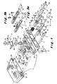
- the illustrated lock comprises a frame 1 composed of a cover box 2, a front cover plate 3 for closing the box 2 and a base plate 4 arranged within the closed box 2.
- the base plate 4 has on its front side an upstanding edge 5 and on its back side two upstanding edge portions 6, 7.
- the cover box 2 has such dimensions that the base plate 4 can be slid completely therein, more particularly through the substantially rectangular front opening 8 of the box 2, even the upstanding edge 5.
- the cover plate 3 is somewhat larger than the front opening 8 so that it engages against the peripheral edge thereof.
- the screws 9, and spacers 11 applied thereover, are further used to fix the lock laterally to the tubular profile of the gate.
- the cover box 2 is provided with two aligned openings 12 through which a cylinder 13 can be inserted in the lock, in particular a so-called Euro-cylinder corresponding to the standard DIN V18254/07.91.
- This key actuated cylinder 13 comprises a rotary driving bit 14 which rotates around a central axis of the cylinder to actuate the lock as described hereinafter.
- the cylinder 13 is fixed in the lock by means of a screw 15 passing through little holes made in the cover plate 3 and in the upstanding edge 5 of the base plate 4.
- the cover box 2 is further provided with two additional aligned openings 16 wherein the door handles can be mounted. These handles as well as their square shaft are known per se and have not been shown in Figure 1, only the door handle rings 17 have been illustrated.
- the illustrated lock further comprises a latch bolt 18 which is slidably mounted in the direction of arrow 19 on the frame 1 of the lock, more particularly within an opening 20 in the upstanding edge portion 6, an opening 21 in the upstanding edge 5 and within an opening 22 in the cover plate 3.
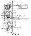
- the latch bolt can thus move between a projecting position shown in Figures 2 and 3 and a retracted position shown in Figure 4.
- a compression spring 23 is applied over the latch bolt 18 to urge this bolt to its projecting position.
- This follower 24 is provided in its turn with a latch bolt lever 25 which follows the rotations of the handles and which engages the latch bolt 18 against the action of a main spring 26 to open this latch bolt.
- the main spring 26 serves to push the latch bolt lever 25 and thus the follower 24 and the handles to their initial rest positions.
- the latch bolt 18 of the lock illustrated in the drawings is made of steel, more particularly of stainless steel. Compared to the usual copper-zinc alloys, steel is much stronger and more weather resistant but is much more difficult to be shaped in the usual way by milling etc. As will become apparent hereinafter, the latch bolt has to have indeed a quite complex shape, especially in order to allow to adjust the length over which it projects out of the lock.
- latch bolt 18 of two separate parts, namely of a hollow rod part 27 which extends at least partially within the lock and a more solid bolt part 28 which is arranged to project out of the lock into a lock catcher.
- the hollow rod part 27 is composed of a U-shaped portion 29 and a cylindrical portion 30. It can simply be pressed out of sheet steel with minimal milling operations.
- the bolt part 28, on the contrary, is made from a solid stainless steel cylindrical rod, wherein an axial passageway is drilled.
- the bolt part 28 On one side, it has an oblique front face and, on the other side, it has a recessed portion 31 by means of which the bolt part 28 can be removably mounted in the hollow rod part 27.
- a screw 32 is provided which can be screwed through an opening in the hollow rod part 27 into a treaded hole 34 in the recessed portion 31 of the bolt part 28. Since this treaded hole 34 (but not the screw 32, except in the embodiment of Figure 5b) extends entirely through the recessed portion 31, the bolt part 28 can be mounted in two different positions, namely in a first position wherein the oblique front face is directed in a first direction and in a second position wherein the bolt part 28 is rotated axially over about 180°.
- the U-shaped portion 29 is provided in the embodiment of Figures 1 to 4 with two opposite slots 35.
- slide means 36 are arranged which project through the slots 35 to form an abutment, on the one hand, for the compression spring 23 and, on the other hand, for the latch bolt lever 25 on one side and for a second turn lever 73 (which will be described hereinafter) on the other side.
- the slide means 36 are fixed with respect to the latch bolt 18 by means of a set screw 37 which is screwed in a treaded hole 38 in the slide means 36.
- the head of the set screw 37 is captured between an inner shoulder, formed at the transition between the U-shaped portion 29 and the cylindrical portion 30 of the latch bolt 18, and the back face of the bolt part 28.
- the slots 35 are replaced by treaded holes 39 wherein a screw 40, forming an abutment for the compression spring 23 and the latch bolt and second turn levers 25 and 73, can be fixed.
- the different positions of the holes 39 correspond to different distances over which the latch bolt 18 projects out of the lock.
- the latch bolt 18 projects over a minimum distance out of the lock, the maximum distance being indicated in dotted line.
- the screw 40 could be replaced by another abutment means which can be fixed into the holes 39 in the latch bolt.
- the lock illustrated in the drawings also comprises a dead bolt 41.
- This dead bolt 41 is essentially made in the same way as the above described latch bolt 18. It is in particular also made of steel, preferably of stainless steel, and comprises a hollow rod part 42 extending at least partially in the lock and a bolt part 43 arranged to co-operate with the lock catcher.
- the hollow rod part 42 can simply be pressed out of sheet steel and comprises a U-shaped portion 44 and a cylindrical portion 45 wherein the bolt part 43 is fixed, more particularly by means of a recessed extremity 46 thereof.
- slide means 47 are arranged which are guided in slots 48 in the dead bolt 43.
- the position of the slide means 47 with respect to the dead bolt 41 can be adjusted by means of a set screw 49 which is accessible through an axial passageway 50 in the bolt part 43 and which is screwed in a treaded hole 51 in the slide means 47.
- this set screw 49 By means of this set screw 49, the distance over which the dead bolt 41 projects out of the lock can thus be continuously adjusted between the extreme positions indicated in Figures 2 to 4.
- the slots are replaced by treaded holes 52 wherein a screw 53 can be fixed.
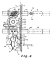
- the two extreme positions of the dead bolt 41 which can thus be achieved, in addition to an intermediate position, are illustrated in Figure 6.
- the dead bolt 41 is slidably mounted in the direction of a double arrow 54 on the frame 1 between a projecting position, illustrated in Figures 2, 3 and 6, and a retracted position, illustrated in Figure 4.
- the dead bolt 41 can more particularly slide in openings 55, 56 and 57 respectively in the upstanding edge portion 7 and the upstanding edge 5 of the frame 1 and in the cover plate 3.
- the dead bolt 41 is not urged by a spring to its projecting position but is locked in both its retracted and projecting positions by means of locking means.
- these locking means comprise a retaining plate 66 which is slidably mounted in the up- and downward direction according to arrow 67 on the frame 1.
- the plate 66 is provided with a slot 68, which form at both ends an upward notch 69.
- the plate 66 is urged downward by means of an end 80 of the main spring 26, which engages an upstanding edge 70 of the plate 66, so that the slide means 47 (or the screw 53 in the embodiment of Figure 5a) project into one of the notches 69 and thus lock the dead bolt in one of its extreme positions.
- the movement of the dead bolt 41 between its two extreme positions is controlled by rotating the key in the cylinder 13, or in other words by the resulting rotation of the rotary driving bit 14.
- this bit 14 When rotating this bit 14, it first of all engages the bottom edge 71 of the retaining plate 66 so that this plate is lifted and the dead bolt is unlocked.
- the rotary driving bit 14 does not act directly upon the dead bolt 41 but instead through the intermediary of a dead bolt lever 58.
- This lever 58 is pivoted about a pivot 59, which fits into a hole 60 in the base plate 4.
- the free extremity of the lever 58, situated opposite the pivot 59, is provided with a slot 61.
- An essential feature of the lock according to the present invention is that the dead bolt lever 58 engages the dead bolt 41 on a first distance D1 from the pivot 59 whilst the dead bolt lever 58 itself is engaged by the rotary driving bit 14 of cylinder 13 on a second distance D2 from this pivot 59, smaller than said first distance D1. Both the first and second distances may vary somewhat between the different positions of the dead lock but, in each position, the second distance D2 should be smaller than the first distance D1. As a result thereof, the stroke of the dead bolt 41 is increased compared to prior art locks wherein the dead bolt 41 is directly engaged by the rotary driving bit 14 of the cylinder 13.
- the driving bit 14 could engage an arm of the dead bolt lever extending below the pivot 59.
- the driving bit 14 engages the dead bolt lever 58 however at a location situated between the dead bolt 41 and the pivot 59, more particularly in a notch 65, so that a compact lock can be achieved and so that the driving bit 14 engages the dead bolt lever 41 over a longer distance due to the circular path followed by the arm of the dead bolt lever 41.
- the cylinder 13 itself is entirely situated between the dead bolt 41 and the pivot 59. In this way, the most preferred embodiment, illustrated in the Figures, can be achieved.
- the pivot 59 is positioned in such a manner that the above described middle point 64, situated centrally between the two engagement points 62 and 63 with the abutment means 47 or 53 on the dead bolt 41, moves from one side of a plane ⁇ perpendicular to the movement direction 54 of the dead bolt 41 and passing through the pivot 59 to the opposite side of this plane ⁇ when the dead bolt 41 moves from its projecting position (illustrated in Figure 2) to its retracted position (illustrated in Figure 3) or vice versa.
- a minimum length of the slot 61 in the dead bolt lever 58 is required to enable the transformation of the rotational movement of this lever 58 into the translational movement of the dead bolt 41.
- a portion of the bottom of the U-shaped portion 44 is cut away so that the free extremity of the dead bolt lever 41 can project through this portion 44 of the dead bolt 41.
- An additional advantage of the presence of the dead bolt lever 58 is that it can be used to move a second turn pusher 72 into and out of the path of the rotary driving bit 14.
- a second turn pusher 72 is connected to a second turn lever 73 arranged to move the latch bolt 18, against the action of the compression spring 23, from its projecting to its retracted position.
- the second turn lever 73 is more particularly rotatably applied over the follower 24 and covered by a washer 74. It has a lever arm 75 which engages the abutment means, i.e. the slide means 36 or the screw 40, on the latch bolt 18 and shows further a hole 76 wherein the free extremity 81 of the pusher 72, which is hook shaped, is applied.
- the pusher 72 is provided with a slot 77 by means of which it is slidably connected to an arm 78 of the dead bolt lever 58.
- This connection between the pusher 72 and the arm 78 of the dead bolt lever 58 is located between the dead bolt 41 and the pivot 59 of the dead bolt lever 58. This means that it is situated at a level below the dead bolt 41 but above the pivot 59. In this way, the movement of the pusher 72 in a direction parallel to the movement of the dead bolt 41 can be kept to a minimum, which is important to enable a compact lock especially in case of an increased stroke of the dead bolt as in the present invention.
- the movement of the pusher 72 has only to be so large that it is out of the path of the rotary driving bit 14 in the projecting position of the dead bolt 41 (illustrated in Figure 2) but comes into this path when the dead bolt moves, upon a first turn of the rotary bit 14, to its retracted position (illustrated in Figure 3).
- this rotary bit 14 engages a hook shaped portion 79 of the pusher 72 and pushes this pusher 72 upwards, as shown in Figure 4, to rotate the second turn lever 73 and thus retract the latch bolt 18.
- the slide means 47 could for example be composed of an elongated slide element, arranged within the U-shaped part of the dead bolt, and a screw screwed transversally into this element and extending through the slots 58.
Landscapes
- Engineering & Computer Science (AREA)
- Structural Engineering (AREA)
- Lock And Its Accessories (AREA)
- Pharmaceuticals Containing Other Organic And Inorganic Compounds (AREA)
- Hydrogenated Pyridines (AREA)
- Arrangement Or Mounting Of Control Devices For Change-Speed Gearing (AREA)
- Gates (AREA)
Priority Applications (6)
| Application Number | Priority Date | Filing Date | Title |
|---|---|---|---|
| DK00870007T DK1118739T3 (da) | 2000-01-21 | 2000-01-21 | Lås |
| EP00870007A EP1118739B1 (de) | 2000-01-21 | 2000-01-21 | Schloss |
| AT00870007T ATE292727T1 (de) | 2000-01-21 | 2000-01-21 | Schloss |
| ES00870007T ES2240049T3 (es) | 2000-01-21 | 2000-01-21 | Cerradura. |
| PT00870007T PT1118739E (pt) | 2000-01-21 | 2000-01-21 | Fechadura |
| DE60019254T DE60019254T2 (de) | 2000-01-21 | 2000-01-21 | Schloss |
Applications Claiming Priority (1)
| Application Number | Priority Date | Filing Date | Title |
|---|---|---|---|
| EP00870007A EP1118739B1 (de) | 2000-01-21 | 2000-01-21 | Schloss |
Publications (2)
| Publication Number | Publication Date |
|---|---|
| EP1118739A1 true EP1118739A1 (de) | 2001-07-25 |
| EP1118739B1 EP1118739B1 (de) | 2005-04-06 |
Family
ID=8175696
Family Applications (1)
| Application Number | Title | Priority Date | Filing Date |
|---|---|---|---|
| EP00870007A Expired - Lifetime EP1118739B1 (de) | 2000-01-21 | 2000-01-21 | Schloss |
Country Status (6)
| Country | Link |
|---|---|
| EP (1) | EP1118739B1 (de) |
| AT (1) | ATE292727T1 (de) |
| DE (1) | DE60019254T2 (de) |
| DK (1) | DK1118739T3 (de) |
| ES (1) | ES2240049T3 (de) |
| PT (1) | PT1118739E (de) |
Cited By (13)
| Publication number | Priority date | Publication date | Assignee | Title |
|---|---|---|---|---|
| EP1367197A1 (de) | 2002-05-27 | 2003-12-03 | Joseph Talpe, Jr. | Schloss |
| EP1367198A1 (de) * | 2002-05-27 | 2003-12-03 | Joseph Talpe, Jr. | Schloss |
| FR2852345A1 (fr) * | 2003-03-07 | 2004-09-17 | Andreas Maier Gmbh Co Andreas | Serrure |
| DE10309946A1 (de) * | 2003-03-07 | 2004-09-23 | Andreas Maier Gmbh & Co. | Schloß |
| US7155945B2 (en) * | 2003-10-24 | 2007-01-02 | Talpe Jr Joseph | Lock having a lockable handle shaft |
| KR101092824B1 (ko) | 2009-10-08 | 2011-12-12 | 주식회사 월드크로스 | 도어용 모티스 락 어셈블리 |
| ITMI20101179A1 (it) * | 2010-06-29 | 2011-12-30 | Iseo Serrature Spa | Serratura stretta a cilindro particolarmente per profilati metallici |
| US8276413B2 (en) | 2006-01-31 | 2012-10-02 | Joseph Talpe | Pushbutton combination lock |
| EP2778323A1 (de) | 2013-03-11 | 2014-09-17 | Joseph Talpe | Schloss, geeignet für links- und rechtsanschlagende Schliesselemente |
| EP2915939A1 (de) | 2014-03-05 | 2015-09-09 | Locinox | Schloss |
| US10927570B2 (en) * | 2018-10-26 | 2021-02-23 | Locinox | Lock for a hinged closure member |
| EP4191006A1 (de) | 2021-12-06 | 2023-06-07 | Locinox | Schloss für ein scharnierverschlusselement |
| EP4191007A1 (de) | 2021-12-06 | 2023-06-07 | Locinox | Schloss für ein scharnierverschlusselement |
Families Citing this family (4)
| Publication number | Priority date | Publication date | Assignee | Title |
|---|---|---|---|---|
| EP2886755B1 (de) | 2013-12-20 | 2017-07-26 | Joseph Talpe | Druckknopf-Kombinationsschloss |
| EP3332901A1 (de) | 2016-12-06 | 2018-06-13 | Locinox | Bohrlehre zur führung einer bohrkrone beim bohren von löchern in einem länglichen element |
| DE102019117867A1 (de) * | 2019-07-02 | 2021-01-07 | Maco Technologie Gmbh | Verschluss mit einem verstärkten gehäuse für ein fenster, eine tür oder dergleichen |
| DE102020002576A1 (de) | 2020-04-29 | 2021-11-04 | Obst Gmbh | Sicherheitsschloss für Türen, insbesondere Außentüren |
Citations (4)
| Publication number | Priority date | Publication date | Assignee | Title |
|---|---|---|---|---|
| GB215501A (en) * | 1923-03-10 | 1924-05-15 | John Wormington Benton | Improvements in or relating to locks for doors and the like |
| DE4118427A1 (de) * | 1991-06-05 | 1992-12-10 | Fuhr Carl Gmbh & Co | Schloss, insbesondere treibstangenschloss |
| EP0828048A2 (de) * | 1996-09-06 | 1998-03-11 | Carl Fuhr GmbH & Co. | Schloss, insbesondere Einsteck-schloss |
| WO1998037295A1 (fr) * | 1997-02-19 | 1998-08-27 | Joseph Talpe | Dispositif de fermeture pour porte |
-
2000
- 2000-01-21 EP EP00870007A patent/EP1118739B1/de not_active Expired - Lifetime
- 2000-01-21 PT PT00870007T patent/PT1118739E/pt unknown
- 2000-01-21 ES ES00870007T patent/ES2240049T3/es not_active Expired - Lifetime
- 2000-01-21 DK DK00870007T patent/DK1118739T3/da active
- 2000-01-21 DE DE60019254T patent/DE60019254T2/de not_active Expired - Lifetime
- 2000-01-21 AT AT00870007T patent/ATE292727T1/de not_active IP Right Cessation
Patent Citations (4)
| Publication number | Priority date | Publication date | Assignee | Title |
|---|---|---|---|---|
| GB215501A (en) * | 1923-03-10 | 1924-05-15 | John Wormington Benton | Improvements in or relating to locks for doors and the like |
| DE4118427A1 (de) * | 1991-06-05 | 1992-12-10 | Fuhr Carl Gmbh & Co | Schloss, insbesondere treibstangenschloss |
| EP0828048A2 (de) * | 1996-09-06 | 1998-03-11 | Carl Fuhr GmbH & Co. | Schloss, insbesondere Einsteck-schloss |
| WO1998037295A1 (fr) * | 1997-02-19 | 1998-08-27 | Joseph Talpe | Dispositif de fermeture pour porte |
Cited By (17)
| Publication number | Priority date | Publication date | Assignee | Title |
|---|---|---|---|---|
| EP1367197A1 (de) | 2002-05-27 | 2003-12-03 | Joseph Talpe, Jr. | Schloss |
| EP1367198A1 (de) * | 2002-05-27 | 2003-12-03 | Joseph Talpe, Jr. | Schloss |
| BE1017308A5 (fr) * | 2003-03-07 | 2008-06-03 | Maier Andreas Gmbh & Co Kg | Serrure. |
| DE10309946A1 (de) * | 2003-03-07 | 2004-09-23 | Andreas Maier Gmbh & Co. | Schloß |
| DE10309946B4 (de) * | 2003-03-07 | 2006-02-09 | Andreas Maier Gmbh & Co. | Schloß |
| DE10309947B4 (de) * | 2003-03-07 | 2006-02-16 | Andreas Maier Gmbh & Co. | Schloß |
| FR2852345A1 (fr) * | 2003-03-07 | 2004-09-17 | Andreas Maier Gmbh Co Andreas | Serrure |
| DE10309947A1 (de) * | 2003-03-07 | 2004-09-23 | Andreas Maier Gmbh & Co. | Schloß |
| US7155945B2 (en) * | 2003-10-24 | 2007-01-02 | Talpe Jr Joseph | Lock having a lockable handle shaft |
| US8276413B2 (en) | 2006-01-31 | 2012-10-02 | Joseph Talpe | Pushbutton combination lock |
| KR101092824B1 (ko) | 2009-10-08 | 2011-12-12 | 주식회사 월드크로스 | 도어용 모티스 락 어셈블리 |
| ITMI20101179A1 (it) * | 2010-06-29 | 2011-12-30 | Iseo Serrature Spa | Serratura stretta a cilindro particolarmente per profilati metallici |
| EP2778323A1 (de) | 2013-03-11 | 2014-09-17 | Joseph Talpe | Schloss, geeignet für links- und rechtsanschlagende Schliesselemente |
| EP2915939A1 (de) | 2014-03-05 | 2015-09-09 | Locinox | Schloss |
| US10927570B2 (en) * | 2018-10-26 | 2021-02-23 | Locinox | Lock for a hinged closure member |
| EP4191006A1 (de) | 2021-12-06 | 2023-06-07 | Locinox | Schloss für ein scharnierverschlusselement |
| EP4191007A1 (de) | 2021-12-06 | 2023-06-07 | Locinox | Schloss für ein scharnierverschlusselement |
Also Published As
| Publication number | Publication date |
|---|---|
| ES2240049T3 (es) | 2005-10-16 |
| DE60019254D1 (de) | 2005-05-12 |
| ATE292727T1 (de) | 2005-04-15 |
| EP1118739B1 (de) | 2005-04-06 |
| PT1118739E (pt) | 2005-08-31 |
| DK1118739T3 (da) | 2005-08-08 |
| DE60019254T2 (de) | 2006-02-16 |
Similar Documents
| Publication | Publication Date | Title |
|---|---|---|
| EP1118739B1 (de) | Schloss | |
| EP2152989B1 (de) | Schliessmechanismus für einen scharnierflügel einer flügeltür oder eines tors | |
| CA2181317C (en) | Multi-point door lock | |
| US4643005A (en) | Multiple-bolt locking mechanism for sliding doors | |
| US7871112B2 (en) | Reversible double deadbolt mortise latch | |
| US6684669B1 (en) | Door fastener device | |
| US20180119462A1 (en) | High security lock for door | |
| US5713612A (en) | Adjustable interconnected lock assembly with automatic deadbolt | |
| US20080078216A1 (en) | Multipoint door lock system with header and sill lock pins | |
| US20060103142A1 (en) | Self-latching device for fastening a hinged closure member | |
| WO2001059237A2 (en) | Multipoint mortise lock | |
| US10246914B2 (en) | Two point lock for bi-fold windows and doors | |
| US20140069154A1 (en) | Reversible door and multipoint lock | |
| US4798065A (en) | Lock having a reversible right and left hand bolt | |
| US20080022729A1 (en) | Improvements in locks | |
| US7213426B2 (en) | Storm door mortise lock that prevents lockout | |
| EP1335085A1 (de) | Verschluss für Schiebetür oder -tor | |
| US20040084909A1 (en) | Single bolt mortise lock | |
| EP0410122B1 (de) | Einsteckschloss mit Fallen-Feststellung | |
| GB2189543A (en) | Multiple bolt locking mechanism for sliding doors | |
| US10927570B2 (en) | Lock for a hinged closure member | |
| US7155945B2 (en) | Lock having a lockable handle shaft | |
| EP0922824B1 (de) | Vorrichtung für die Betätigung eines Panikschlosses von aussen | |
| US4590777A (en) | Doorlock | |
| WO2005106165A2 (en) | Improvements in mortice latches |
Legal Events
| Date | Code | Title | Description |
|---|---|---|---|
| PUAI | Public reference made under article 153(3) epc to a published international application that has entered the european phase |
Free format text: ORIGINAL CODE: 0009012 |
|
| AK | Designated contracting states |
Kind code of ref document: A1 Designated state(s): AT BE CH CY DE DK ES FI FR GB GR IE IT LI LU MC NL PT SE |
|
| AX | Request for extension of the european patent |
Free format text: AL;LT;LV;MK;RO;SI |
|
| 17P | Request for examination filed |
Effective date: 20011130 |
|
| AKX | Designation fees paid |
Free format text: AT BE CH CY DE DK ES FI FR GB GR IE IT LI LU MC NL PT SE |
|
| 17Q | First examination report despatched |
Effective date: 20020729 |
|
| GRAP | Despatch of communication of intention to grant a patent |
Free format text: ORIGINAL CODE: EPIDOSNIGR1 |
|
| GRAS | Grant fee paid |
Free format text: ORIGINAL CODE: EPIDOSNIGR3 |
|
| GRAA | (expected) grant |
Free format text: ORIGINAL CODE: 0009210 |
|
| AK | Designated contracting states |
Kind code of ref document: B1 Designated state(s): AT BE CH CY DE DK ES FI FR GB GR IE IT LI LU MC NL PT SE |
|
| PG25 | Lapsed in a contracting state [announced via postgrant information from national office to epo] |
Ref country code: FI Free format text: LAPSE BECAUSE OF FAILURE TO SUBMIT A TRANSLATION OF THE DESCRIPTION OR TO PAY THE FEE WITHIN THE PRESCRIBED TIME-LIMIT Effective date: 20050406 |
|
| REG | Reference to a national code |
Ref country code: GB Ref legal event code: FG4D |
|
| REG | Reference to a national code |
Ref country code: CH Ref legal event code: EP |
|
| REG | Reference to a national code |
Ref country code: IE Ref legal event code: FG4D |
|
| REF | Corresponds to: |
Ref document number: 60019254 Country of ref document: DE Date of ref document: 20050512 Kind code of ref document: P |
|
| PG25 | Lapsed in a contracting state [announced via postgrant information from national office to epo] |
Ref country code: GR Free format text: LAPSE BECAUSE OF FAILURE TO SUBMIT A TRANSLATION OF THE DESCRIPTION OR TO PAY THE FEE WITHIN THE PRESCRIBED TIME-LIMIT Effective date: 20050706 |
|
| REG | Reference to a national code |
Ref country code: CH Ref legal event code: NV Representative=s name: R. A. EGLI & CO. PATENTANWAELTE |
|
| REG | Reference to a national code |
Ref country code: SE Ref legal event code: TRGR |
|
| REG | Reference to a national code |
Ref country code: DK Ref legal event code: T3 |
|
| REG | Reference to a national code |
Ref country code: PT Ref legal event code: SC4A Effective date: 20050701 |
|
| REG | Reference to a national code |
Ref country code: ES Ref legal event code: FG2A Ref document number: 2240049 Country of ref document: ES Kind code of ref document: T3 |
|
| PG25 | Lapsed in a contracting state [announced via postgrant information from national office to epo] |
Ref country code: MC Free format text: LAPSE BECAUSE OF NON-PAYMENT OF DUE FEES Effective date: 20060131 |
|
| PLBE | No opposition filed within time limit |
Free format text: ORIGINAL CODE: 0009261 |
|
| STAA | Information on the status of an ep patent application or granted ep patent |
Free format text: STATUS: NO OPPOSITION FILED WITHIN TIME LIMIT |
|
| ET | Fr: translation filed | ||
| 26N | No opposition filed |
Effective date: 20060110 |
|
| PG25 | Lapsed in a contracting state [announced via postgrant information from national office to epo] |
Ref country code: CY Free format text: LAPSE BECAUSE OF FAILURE TO SUBMIT A TRANSLATION OF THE DESCRIPTION OR TO PAY THE FEE WITHIN THE PRESCRIBED TIME-LIMIT Effective date: 20050406 |
|
| PGFP | Annual fee paid to national office [announced via postgrant information from national office to epo] |
Ref country code: SE Payment date: 20091223 Year of fee payment: 11 |
|
| PGFP | Annual fee paid to national office [announced via postgrant information from national office to epo] |
Ref country code: DK Payment date: 20100113 Year of fee payment: 11 Ref country code: LU Payment date: 20100119 Year of fee payment: 11 Ref country code: ES Payment date: 20100125 Year of fee payment: 11 Ref country code: PT Payment date: 20100114 Year of fee payment: 11 Ref country code: IE Payment date: 20100121 Year of fee payment: 11 Ref country code: CH Payment date: 20100125 Year of fee payment: 11 |
|
| PGFP | Annual fee paid to national office [announced via postgrant information from national office to epo] |
Ref country code: AT Payment date: 20100114 Year of fee payment: 11 |
|
| REG | Reference to a national code |
Ref country code: PT Ref legal event code: MM4A Free format text: LAPSE DUE TO NON-PAYMENT OF FEES Effective date: 20110721 |
|
| REG | Reference to a national code |
Ref country code: DK Ref legal event code: EBP |
|
| REG | Reference to a national code |
Ref country code: CH Ref legal event code: PL |
|
| REG | Reference to a national code |
Ref country code: SE Ref legal event code: EUG |
|
| REG | Reference to a national code |
Ref country code: IE Ref legal event code: MM4A |
|
| PG25 | Lapsed in a contracting state [announced via postgrant information from national office to epo] |
Ref country code: CH Free format text: LAPSE BECAUSE OF NON-PAYMENT OF DUE FEES Effective date: 20110131 Ref country code: LI Free format text: LAPSE BECAUSE OF NON-PAYMENT OF DUE FEES Effective date: 20110131 Ref country code: PT Free format text: LAPSE BECAUSE OF NON-PAYMENT OF DUE FEES Effective date: 20110721 |
|
| PG25 | Lapsed in a contracting state [announced via postgrant information from national office to epo] |
Ref country code: AT Free format text: LAPSE BECAUSE OF NON-PAYMENT OF DUE FEES Effective date: 20110121 |
|
| PG25 | Lapsed in a contracting state [announced via postgrant information from national office to epo] |
Ref country code: IE Free format text: LAPSE BECAUSE OF NON-PAYMENT OF DUE FEES Effective date: 20110121 |
|
| REG | Reference to a national code |
Ref country code: ES Ref legal event code: FD2A Effective date: 20120220 |
|
| PG25 | Lapsed in a contracting state [announced via postgrant information from national office to epo] |
Ref country code: ES Free format text: LAPSE BECAUSE OF NON-PAYMENT OF DUE FEES Effective date: 20110122 |
|
| PG25 | Lapsed in a contracting state [announced via postgrant information from national office to epo] |
Ref country code: SE Free format text: LAPSE BECAUSE OF NON-PAYMENT OF DUE FEES Effective date: 20110122 |
|
| PG25 | Lapsed in a contracting state [announced via postgrant information from national office to epo] |
Ref country code: LU Free format text: LAPSE BECAUSE OF NON-PAYMENT OF DUE FEES Effective date: 20110121 |
|
| REG | Reference to a national code |
Ref country code: FR Ref legal event code: PLFP Year of fee payment: 17 |
|
| REG | Reference to a national code |
Ref country code: FR Ref legal event code: PLFP Year of fee payment: 18 |
|
| REG | Reference to a national code |
Ref country code: FR Ref legal event code: PLFP Year of fee payment: 19 |
|
| PGFP | Annual fee paid to national office [announced via postgrant information from national office to epo] |
Ref country code: NL Payment date: 20181213 Year of fee payment: 20 |
|
| PGFP | Annual fee paid to national office [announced via postgrant information from national office to epo] |
Ref country code: FR Payment date: 20181213 Year of fee payment: 20 Ref country code: BE Payment date: 20181213 Year of fee payment: 20 |
|
| PGFP | Annual fee paid to national office [announced via postgrant information from national office to epo] |
Ref country code: GB Payment date: 20190121 Year of fee payment: 20 Ref country code: IT Payment date: 20190124 Year of fee payment: 20 Ref country code: DE Payment date: 20190123 Year of fee payment: 20 |
|
| REG | Reference to a national code |
Ref country code: DE Ref legal event code: R071 Ref document number: 60019254 Country of ref document: DE |
|
| REG | Reference to a national code |
Ref country code: NL Ref legal event code: MK Effective date: 20200120 |
|
| REG | Reference to a national code |
Ref country code: GB Ref legal event code: PE20 Expiry date: 20200120 |
|
| REG | Reference to a national code |
Ref country code: BE Ref legal event code: MK Effective date: 20200121 |
|
| PG25 | Lapsed in a contracting state [announced via postgrant information from national office to epo] |
Ref country code: GB Free format text: LAPSE BECAUSE OF EXPIRATION OF PROTECTION Effective date: 20200120 |