EP1118709A2 - Auftragsvorrichtung - Google Patents
Auftragsvorrichtung Download PDFInfo
- Publication number
- EP1118709A2 EP1118709A2 EP01100243A EP01100243A EP1118709A2 EP 1118709 A2 EP1118709 A2 EP 1118709A2 EP 01100243 A EP01100243 A EP 01100243A EP 01100243 A EP01100243 A EP 01100243A EP 1118709 A2 EP1118709 A2 EP 1118709A2
- Authority
- EP
- European Patent Office
- Prior art keywords
- application device
- nozzle
- application
- blade element
- adjusting
- Prior art date
- Legal status (The legal status is an assumption and is not a legal conclusion. Google has not performed a legal analysis and makes no representation as to the accuracy of the status listed.)
- Granted
Links
Images



Classifications
-
- D—TEXTILES; PAPER
- D21—PAPER-MAKING; PRODUCTION OF CELLULOSE
- D21H—PULP COMPOSITIONS; PREPARATION THEREOF NOT COVERED BY SUBCLASSES D21C OR D21D; IMPREGNATING OR COATING OF PAPER; TREATMENT OF FINISHED PAPER NOT COVERED BY CLASS B31 OR SUBCLASS D21G; PAPER NOT OTHERWISE PROVIDED FOR
- D21H23/00—Processes or apparatus for adding material to the pulp or to the paper
- D21H23/02—Processes or apparatus for adding material to the pulp or to the paper characterised by the manner in which substances are added
- D21H23/22—Addition to the formed paper
- D21H23/32—Addition to the formed paper by contacting paper with an excess of material, e.g. from a reservoir or in a manner necessitating removal of applied excess material from the paper
- D21H23/34—Knife or blade type coaters
- D21H23/36—Knife or blade forming part of the fluid reservoir, e.g. puddle-type trailing blade or short-dwell coaters
-
- B—PERFORMING OPERATIONS; TRANSPORTING
- B05—SPRAYING OR ATOMISING IN GENERAL; APPLYING FLUENT MATERIALS TO SURFACES, IN GENERAL
- B05C—APPARATUS FOR APPLYING FLUENT MATERIALS TO SURFACES, IN GENERAL
- B05C5/00—Apparatus in which liquid or other fluent material is projected, poured or allowed to flow on to the surface of the work
- B05C5/02—Apparatus in which liquid or other fluent material is projected, poured or allowed to flow on to the surface of the work the liquid or other fluent material being discharged through an outlet orifice by pressure, e.g. from an outlet device in contact or almost in contact, with the work
- B05C5/0254—Coating heads with slot-shaped outlet
- B05C5/0262—Coating heads with slot-shaped outlet adjustable in width, i.e. having lips movable relative to each other in order to modify the slot width, e.g. to close it
-
- B—PERFORMING OPERATIONS; TRANSPORTING
- B05—SPRAYING OR ATOMISING IN GENERAL; APPLYING FLUENT MATERIALS TO SURFACES, IN GENERAL
- B05C—APPARATUS FOR APPLYING FLUENT MATERIALS TO SURFACES, IN GENERAL
- B05C5/00—Apparatus in which liquid or other fluent material is projected, poured or allowed to flow on to the surface of the work
- B05C5/02—Apparatus in which liquid or other fluent material is projected, poured or allowed to flow on to the surface of the work the liquid or other fluent material being discharged through an outlet orifice by pressure, e.g. from an outlet device in contact or almost in contact, with the work
- B05C5/0283—Flat jet coaters, i.e. apparatus in which the liquid or other fluent material is projected from the outlet as a cohesive flat jet in direction of the work
Definitions
- the invention relates to a device for applying liquid or pasty application medium on a running surface, the When applying directly, the surface of a material web, in particular made of paper or cardboard, and with indirect application the surface a transfer element, preferably a transfer roller, which then applies the application medium to the surface of the material web transfers, and wherein the applicator has a dispensing nozzle for dispensing of the application medium to the surface includes with a reference the movement of the substrate inlet lip and one with respect to the movement of the substrate on the outlet-side nozzle lip.
- EP 0 846 804 A1 and US 5,603,767 are generic free jet nozzle applicators known in which one of the two nozzle lips is rigidly arranged, while the other nozzle lip by means of the adjustment device for Change in the width of the nozzle gap can be influenced. None of the known free jet nozzle application devices, however, it is possible to quickly adjust or open the nozzle gap in the short term in order to For example, "blow out" contaminants that affect the order result adversely affect.
- an application device of the beginning Provide mentioned type, which an improved adjustment the width of the nozzle gap offers.
- a blade element When using such a elastic nozzle lip can thereby easily the nozzle gap can be expanded quickly and in the short term, that you can put the pressure in the application medium supplied to the nozzle gap for a short period of time elevated.
- Such a pressure pulse expands due to the deformation of the Blade element not only loosens the nozzle gap, it also loosens if necessary existing impurities and blows them out of the nozzle gap. After the pressure pulse has ended, the blade element returns automatically back to its original position, so that the nozzle gap reliably again assumes its original width.
- the blade element is preferably made of Made of steel. However, it is also possible to use blade elements made of fiber-reinforced Use plastic, especially blade elements carbon fiber reinforced plastic (CFRP), made of glass fiber reinforced plastic (GFK) or the like.
- the application device also a device for operational adjustment of the Width of the nozzle gap, i.e. a device with which the pro Unit of time delivered by the application device to the running surface Amount of application medium can be varied.
- the adjustment device act on the blade element.
- the Blade element can be bent by means of an adjusting unit of the adjusting device or is pivotable. Namely, the width of the nozzle gap can go out from a state unaffected by the adjusting device of the blade element with increasing actuation of the adjustment device either increase or alternatively decrease.
- the case of increase can be done in a structurally simple manner, for example can be realized in that the blade element with one of its (in Longitudinal edges) held on the applicator and arranged on one between its two longitudinal edges Position is supported on the applicator, and that the actuator at one between the support position and the longitudinal holding edge arranged position acts on the blade element.
- the case of acceptance can be done in a structurally simple manner, for example can be realized in that the blade element with only one its (transverse) longitudinal edges on the applicator is held and that the actuating unit on one between the longitudinal holding edge and the free longitudinal edge arranged position on the Blade element acts and this bends.
- Blade element can also be included in a pivot bearing.
- the adjustment device can the blade element against spring preload swivel.
- the adjustment device comprises two partial adjustment devices, which in opposite Apply directions to the blade element.
- the gap width is in this state essentially independent of the actuating force of the adjusting device, which simplifies the control of the application device.
- At least one securing element can also be used be provided, which cooperates with the blade element and this in the holder receptacle of the application device assigned to it backs up.
- the actuating unit can, for example, have at least one tilting Have lever comprising rocker arm assembly, with a free end the rocker arm arrangement acts on the blade element and wherein each other free end of the rocker arm arrangement by means of at least one a power device arrangement comprising a power device is movable.
- the power device assembly needs not located in the immediate vicinity of the dispensing nozzle to be where there is usually little space available, but can be in a location that is less critical with regard to the installation space to be placed.
- a power device arrangement Pressure hose arrangement into consideration.
- weight machines but also other pneumatic, hydraulic, hydropneumatic, electrical, electromotive, electrochemical or other suitable Ways that can be operated are used.
- the power device arrangement comprises a plurality of power devices, then these can be arranged distributed in the transverse direction of the substrate. This allows the width of the nozzle gap in a corresponding A plurality of cross sections independent of the working width of the subsurface from each other, which is a cross-profiling of the layer of application medium applied to the running surface.
- the rocker bearing of the rocker arm assembly and / or the at least one Power equipment can each on the distribution pipe or one connected to it Part be arranged.
- the blade element in one means the adjustment device adjustable holder is added.
- the holder can comprise a cylindrical segment-shaped joint body, which is preferably received in an acetabular cup the distribution pipe or a part connected to it is formed.
- the adjustment device can, for example, on this joint body attack on the side of the application device, on the drive side or / and the operator side of the application device, where sufficient Space is available.
- the adjustment device which leaves a nozzle element comprising a blade element unaffected and acts on the other nozzle lip.
- That other nozzle lip can in turn be assigned a cylindrical segment-shaped joint body be movable by means of the adjusting device in a socket which is preferably on the distribution pipe or one with this connected part is formed.
- the other nozzle lip either be an element held in the joint body or with be formed in one piece the joint body. In the latter case it is advantageous in terms of fluid dynamics if the joint body essentially has a has a teardrop-shaped cross-section, i.e. in the area of in the Joint socket recorded portion of the joint body essentially follows the outline of a circle as it moves in the The section forming the nozzle lip is tapered at an acute angle.
- the adjustment device can be on at least one of the longitudinal ends attack the joint body, i.e. on the driver's side or / and the drive side of the coating machine.
- an adjustment device is assigned to both nozzle lips, so can in the application device according to the invention by accordingly coordinated influence of the position of the two nozzle lips not only the width of the nozzle gap can be influenced, but also the direction the jet of application medium emerging from the dispensing nozzle, and this without the location of the entire application device would have to be changed.
- This is particularly advantageous because the adjustment or tracking of the application medium jet to the The most favorable beam angle with respect to the running surface by adjusting parts of relatively low inertia and thus can be done accordingly quickly. Hence for this thought independent protection sought.
- the position of both nozzle lips can be influenced, for example can also be used in such a way that one of the blade element formed nozzle lip from a rest position to an operating position brings and keeps in it.
- that Blade element can be driven against a stop, as above has already been addressed.
- the width of the nozzle gap is in normal operation by influencing the position of the other Nozzle lip set. However, it is for "rinsing" the nozzle gap possible, the blade element briefly from the operating position to the rest position attributed.
- the expansion of the can be created by means of a pressure pulse caused expansion of the nozzle gap are supported.
- At least comprises two shell parts, which together form the boundary wall one of the dispensing nozzle with respect to the supply flow of the application medium form upstream distribution channel.
- shell parts are in particular casting or extrusion technically easier to manufacture than Pipe profile parts, whereby the manufacture of the application device according to the invention simplified.
- the two shell parts can, for example made of fiber-reinforced plastic, in particular carbon fiber-reinforced Plastic (CFRP), or polyvinyl chloride (PVC), in particular chlorinated polyvinyl chloride (PVC-C). You can with each other in a simple manner by gluing, screwing or the like be connected. Also for the idea of training the application device independent protection is sought from two shell parts.
- the shell parts can also jointly one between the distribution channel and the compensation chamber arranged in the dispensing nozzle, in which is the flow of the application medium emerging from the distribution channel is evened out before it is fed to the dispensing nozzle becomes.
- On the shell parts can also recordings for a respective assigned nozzle lip or its holder is formed his.
- This insert part can according to the invention as a "diaphragm device" between the distribution channel and serve the compensation chamber and can for example at Transition from one order medium type to another, for example in Adaptation to the viscosity of the new application medium type against another Insert part, which is a larger or smaller number of transfer openings and / or transfer openings has larger or smaller passage cross-section.
- a simplification of the structure of the application device according to the invention and the superordinate construction parts can be achieved be that the distribution pipe from the support body assigned to it, for example, support beam, is formed separately.
- This modular Design allows it in a simple manner, the distribution pipe on the support body to be arranged thermally insulated. This makes it possible to prevent that differences in linear expansion between support body and distribution pipe to tensions of the overall arrangement, in particular to tensions of the distribution pipe. Different coefficients of thermal expansion the materials used for the different parts can therefore not adversely affect the order result impact.
- the application device according to the invention also as Application medium curtain application device (curtain coater) or as application device with short exposure time (SDTA - short dwell time applicator) can be used.
- the nozzle gap forms the application chamber in which the application medium is brought into contact with the running substrate for the short dwell time, this application chamber being delimited by the two nozzle lips.
- the outlet-side nozzle lip can be designed as a device for final metering and, if desired, leveling out the layer of application medium applied to the substrate.
- a finished metering / leveling device of this type can also merely be arranged on the outlet-side nozzle lip.
- the application medium is applied according to the principle of gravity. The order quantity can only be so small that a finished dosage or leveling is no longer necessary.
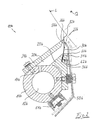
- an application device is generally 10a designated. It is used to apply a liquid or pasty application medium 12a on a moving in the direction of arrow L.
- Underground U for example the surface of a material web, in particular made of paper or cardboard (direct order) or the surface a transfer roller, which then the application medium at a different position transferred to the material web (indirect order).
- the application device 10a comprises a distribution pipe 14a, in the interior thereof 16a the application medium 12a in the transverse direction Q of the substrate U is fed. A is distributed in the transverse direction Q in the distribution pipe 14a A plurality of passage openings 18a are provided through which the Application medium 12a enters an equalization space 20a, which is in the Extends essentially over the entire working width of the underground U. and to even out the flow of the outlets 18a emerging application medium 12a is used. Through the compensation chamber 20a, the application medium 12a flows through to a discharge nozzle 22a which it exits from the application device 10a as a jet and with which running underground U is brought into contact.
- the compensation chamber 20a is essentially one rigid, plate-shaped element 24a bounded to the distribution pipe 14a is attached and at the free end of the outlet-side nozzle lip 26a is trained.
- the equalization chamber 20a becomes one Top part 28a limited, which is also attached to the distribution pipe 14a and also serves to hold a blade element 30a.
- the free The inlet-side nozzle lip 32a forms the end of the blade element 30a Dispensing nozzle 22a.
- Fastening the parts of the compensation chamber delimitation elements 24a and 28a on the distribution pipe 14a is preferably carried out by screwing. This is particularly advantageous for part 24a because it its replacement when the outlet-side nozzle lip 26a is worn enables simple way.
- the blade element 30a is opposite to the nozzle lip end 32a Holding end 34a in a holding recess 36a of the second Compensation chamber limiting element 28a added.
- An expression 38a of the blade element 30a acts with a shoulder 40a of the second compensation chamber delimiting element 28a together and prevents the blade element 30a in FIG Holding recess 36a moved out.
- the blade element lies 30a on a section 42a of the second compensation chamber delimitation element 28a.
- a rocker arm 50a is provided which is in a rocker bearing 52a is pivotally mounted.
- the tilt bearing 52a is on the second compensation chamber delimitation element 28a arranged.
- the lower in Fig. 1 free end of the rocker arm 50a is an adjusting device 54a (according to Fig. 1 assigned a pressure hose assembly), by means of which the rocker arm 50a can be pivoted in the tilting bearing 52a.
- Fig. 1 upper free end of the rocker arm 50a acts on the blade member 30a, namely at one between the holding recess 36a and the Support position 56a of the blade member 30a on the support portion 42a of the second compensation chamber delimiting element 28a Position.
- FIG. 2 shows a further embodiment of an application device according to the invention shown, which is essentially the application device 1 corresponds. Analog parts are therefore the same in FIG. 2 Reference numerals as in Fig. 1, but with the lower case “b" instead of "a".
- the embodiment according to FIG. 2 are only described to the extent that they differ from the Embodiment according to FIG. 1 differs on the description thereof hereby otherwise expressly referred.
- the application device 10b according to FIG. 2 differs from the application device 1 mainly due to the fact that the rocker arm 50b with increasing actuation of the adjusting device 54b, i.e. at Increasing the gas pressure in the pressure hose, the blade element 30b bent to reduce the width of the nozzle gap 58b. This is achieved in that the blade element 30b is only over in the holding recess 36b received end 34b with the second Compensation chamber limiting element 28b is connected but does not support this at any other point. As with the embodiment 1, however, the respective width of the Nozzle gap 58b in an interplay of the actuating force of the actuating device 54b and the spring force of the bent blade member 30b.
- the second compensation chamber delimitation element 28b a stop 60b for the rocker arm 50b provided that a state of maximum bending of the Blade element 30b and thus the minimum width of the nozzle gap 58b specifies.
- a locking pin 62b provided in the second compensation chamber delimiting element is guided such that it is from the rocker arm 50b is urged into holding engagement with the blade element 30b and this in the holding recess 36b secures.
- FIG. 3 shows a further embodiment of an application device according to the invention shown, which are essentially those explained above Application devices corresponds. Analog parts are therefore in Fig. 3 provided with the same reference numerals as in Fig. 1, but with the Lowercase “c” instead of "a". In addition, the embodiment 3 are described below only in so far, than it differs from the previous embodiments, otherwise, reference is expressly made to the description thereof.
- the application device 10c corresponds to the construction in FIG. 3 and function of essentially the application device 10b according to FIG. 2, in particular what the dispensing nozzle 20c for dispensing application medium 12c and their nozzle lips 26c and 32c.
- FIG. 4 shows a further embodiment of an application device according to the invention shown, which are essentially those explained above Application devices corresponds. Analog parts are therefore in Fig. 4 provided with the same reference numerals as in Fig. 1, but with the Lowercase “d” instead of "a". In addition, the embodiment 4 are described below only in so far, than it differs from the previous embodiments, otherwise, reference is expressly made to the description thereof.
- the application medium 12d in a distribution channel 16d of the distribution pipe 14d supplied by two Shell elements 70d and 72d is delimited.
- the compensation room 20d is also in the embodiment shown in FIG the two shell elements 70d and 72 limited.
- the free End the inlet-side nozzle lip 32d of the nozzle gap 58d forms the compensation space 20d adjoining discharge nozzle 22d.
- the outlet-side nozzle lip 26d is essentially at a cross-section teardrop-shaped joint body 80d formed in one on the first Shell part 70d formed socket 82d about the axis A. is pivotally mounted. To set the desired one
- the pivot position of the joint body 80d is only schematic in FIG. 4 shown adjustment device V (for example a lever arrangement) provided on at least one of the two longitudinal ends of the joint body 80d, i.e. on the driver side and / or the drive side of the application device 10d, attacks.
- FIG. 4 are representative of the design variants described so far 1-3 as well as for the following descriptive variants, existing support arms 81 drawn in for supporting the application device on a support unit T (e.g. Squeegee).
- the support arms are on the distribution pipe 14 (according to Fig. 1-3) or on the shell part 70 (according to FIG. 4 and others) articulated and in a distance of approx. 1200 mm from each other over the entire Machine or device width distributed. This is on simple way the thermal separation between distribution pipe and support body realizable.
- FIG. 5 shows a further embodiment of an application device according to the invention shown, which are essentially those explained above Application devices, in particular the embodiment 4 corresponds. Analog parts are therefore the same in FIG. 5 Reference numerals as in Fig. 1, but with the lower case “e” instead of "a". In addition, the embodiment according to FIG. 5 are only described to the extent that they differ from the distinguishes above embodiments, based on their description hereby otherwise expressly referred.
- a joint body 80e is assigned to the outlet-side nozzle tip 26e, that can be pivoted in a joint socket 82e of the first shell part 70e is mounted, but also a joint body of the inlet-side nozzle tip 32e 84e is assigned to that in a joint socket 86e of the second Shell part 72e is pivotally mounted.
- This can not only Width of the nozzle gap 58e of the discharge nozzle 22e can be varied, but also the direction in which the jet of application medium 12e the dispensing nozzle 22e leaves.
- both nozzle lips 26e and 32e are on blade elements 30e and 88e formed, which are held in the joint bodies 80e and 84e are.
- Insert part 78e is otherwise on the description of the embodiment referenced in FIG. 4.
- FIG. 6 shows a further embodiment of an application device according to the invention shown, which are essentially those explained above Application devices corresponds. Analog parts are therefore in Fig. 6 provided with the same reference numerals as in Fig. 1, but with the Lowercase “f” instead of "a". In addition, the embodiment 6 are described below only in so far, than it differs from the previous embodiments, otherwise, reference is expressly made to the description thereof.
- the blade element by means of a locking pin 62f in the holding recess 36f
- 30f is held in a pivot bearing 90f, which of two round cords is formed.
- One of the round cords is in one Recess of the second integral with the distribution pipe 14f Compensation chamber limiting element 28f added during the second round cord received in a recess of a cover body 98f is.
- the adjustment device 54f for the blade element 30f comprises two pressure hose assemblies 92f and 94f, which on the blade element 30f act from opposite sides. Doing so the pressure hose arrangement 92f the blade element 30f in its operating position against stop surfaces 60f.
- the adjustment device for the first compensation chamber delimiting element having the nozzle lip 26f 24f that at 100f on the manifold 14f is pivotally mounted is roughly schematic in Fig. 6 at 96f indicated.
Landscapes
- Coating Apparatus (AREA)
- Confectionery (AREA)
- Massaging Devices (AREA)
Abstract
Description
Im Fall des curtain coaters wird das Auftragsmedium dem Prinzip der Schwerkraft folgend aufgebracht. Dabei kann die Auftragsmenge nur so gering sein, dass eine Fertigdosierung bzw. Egalisierung nicht mehr erforderlich ist.
- Fig. 1 - 6
- schematische Seitenschnittansichten erfindungsgemäßer Auftragsvorrichtungen.
Claims (31)
- Vorrichtung (10a-10f) zum Auftragen von flüssigem oder pastösem Auftragsmedium (12a-12f) auf einen laufenden Untergrund (U),dadurch gekennzeichnet, dass wenigstens eine (32a-32f) der Düsenlippen von einem Klingenelement (30a-30f) gebildet ist.wobei der Untergrund bei direktem Auftrag die Oberfläche einer Materialbahn, insbesondere aus Papier oder Karton, und bei indirektem Auftrag die Oberfläche eines Übertragselements, vorzugsweise einer Übertragswalze, ist, welches das Auftragsmedium dann an die Oberfläche der Materialbahn überträgt, undwobei die Auftragsvorrichtung eine Abgabedüse (22a-22f) zum Abgeben des Auftragsmediums (12a-12f) an den Untergrund (U) umfasst mit einer bezüglich der Bewegung des Untergrunds zulaufseitigen Düsenlippe (32a-32f) und einer bezüglich der Bewegung des Untergrunds ablaufseitigen Düsenlippe (26a-26f),
- Auftragsvorrichtung nach Anspruch 1,
dadurch gekennzeichnet, dass eine Vorrichtung (50a/54a; 50b/54b; 54f/92f/94f) zum betriebsmäßigen Verstellen der Weite des Düsenspalts (58a-58f) vorgesehen ist. - Auftragsvorrichtung nach Anspruch 2,
dadurch gekennzeichnet, dass die Verstellvorrichtung (50a/54a; 50b/54b; 54f/92f/94f) auf das Klingenelement (30a-30c; 30f) einwirkt. - Auftragsvorrichtung nach Anspruch 3,
dadurch gekennzeichnet, dass das Klingenelement (30a-30c; 30f) mittels einer Stelleinheit (50a; 50b; 92f/94f) der Verstellvorrichtung verbiegbar oder verschwenkbar ist. - Auftragsvorrichtung nach Anspruch 3 oder 4,
dadurch gekennzeichnet, dass die Weite des Düsenspalts (58a; 58f) ausgehend von einem von der Verstellvorrichtung (50a/54a; 54f/92f/94f) unbeeinflussten Zustand des Klingenelements (30a; 30f) mit zunehmender Betätigung der Verstellvorrichtung zunimmt. - Auftragsvorrichtung nach einem der Ansprüche 3 bis 5,
dadurch gekennzeichnet, dass das Klingenelement (30a) mit einer seiner Längskanten (34a) an der Auftragsvorrichtung gehalten und an einer zwischen seinen beiden Längskanten angeordneten Position (42a) an der Auftragsvorrichtung abgestützt ist, und dass die Stelleinheit (50a) an einer zwischen der Stützposition (42a) und der Halte-Längskante (34a) angeordneten Position auf das Klingenelement (30a) einwirkt. - Auftragsvorrichtung nach einem der Ansprüche 3 bis 6,
dadurch gekennzeichnet, dass die Weite des Düsenspalts (58b; 58c; 58f) ausgehend von einem von der Verstellvorrichtung unbeeinflussten Zustand des Klingenelements (30b; 30c; 30f) mit zunehmender Betätigung der Verstellvorrichtung abnimmt. - Auftragsvorrichtung nach einem der Ansprüche 1 bis 7,
dadurch gekennzeichnet, dass das Klingenelement (30f) in einem Schwenklager (90f) aufgenommen ist. - Auftragsvorrichtung nach einem der Ansprüche 3 bis 8,
dadurch gekennzeichnet, dass die Verstellvorrichtung (54f) zwei Teil-Verstellvorrichtungen (92f, 94f) umfasst, welche in entgegengesetzten Richtungen auf das Klingenelement (30f) einwirken. - Auftragsvorrichtung nach einem der Ansprüche 3 bis 9,
dadurch gekennzeichnet, dass ein Anschlag (60b; 60c; 60f) vorgesehen ist, der einen Zustand maximaler Verbiegung oder Verschwenkung des Klingenelements (30b; 30c; 30f) definiert. - Auftragsvorrichtung nach einem der Ansprüche 1 bis 10,
dadurch gekennzeichnet, dass ein Sicherungselement (62b; 62f) vorgesehen ist, welches mit dem Klingenelement (30b; 30f) zusammenwirkt und dieses in der ihm zugeordneten Halterungsaufnahme (36b; 36f) sichert. - Auftragsvorrichtung nach einem der Ansprüche 4 bis 11,
dadurch gekennzeichnet, dass die Stelleinheit eine wenigstens einen kippbar gelagerten Hebel umfassende Kipphebelanordnung (50a; 50b) aufweist, wobei ein freies Ende der Kipphebelanordnung auf das Klingenelement (30a; 30b; 30c) einwirkt und wobei das jeweils andere freie Ende der Kipphebelanordnung (50a; 50b) mittels einer wenigstens ein Kraftgerät umfassenden Kraftgerätanordnung (54a; 54b) bewegbar ist. - Auftragsvorrichtung nach Anspruch 12,
dadurch gekennzeichnet, dass das Kipplager (52a) an dem Verteilrohr bzw. einem mit diesem verbundenen Teil (28a) angeordnet ist. - Auftragsvorrichtung nach Anspruch 12 oder 13,
dadurch gekennzeichnet, dass das wenigstens eine Kraftgerät (54a) an dem Verteilrohr (14a) bzw. einem mit diesem verbundenen Teil angeordnet ist. - Auftragsvorrichtung nach Anspruch 3,
dadurch gekennzeichnet, dass das Klingenelement (30e) in einer mittels der Verstellvorrichtung verstellbaren Halterung (84e) aufgenommen ist. - Auftragsvorrichtung nach Anspruch 14,
dadurch gekennzeichnet, dass die Halterung einen zylindersegmentförmigen Gelenkkörper (84e) umfasst. - Auftragsvorrichtung nach Anspruch 16,
dadurch gekennzeichnet, dass der zylindersegmentförmige Gelenkkörper (84e) in einer Gelenkpfanne (86e) aufgenommen ist, die an dem Verteilrohr (14e) bzw. einem mit diesem verbundenen Teil ausgebildet ist. - Auftragsvorrichtung nach Anspruch 2,
dadurch gekennzeichnet, dass die Verstellvorrichtung die ein Klingenelement (30d) umfassende Düsenlippe (32d) unbeeinflusst lässt und auf die jeweils andere Düsenlippe (26d) einwirkt. - Auftragsvorrichtung nach Anspruch 17,
dadurch gekennzeichnet, dass der anderen Düsenlippe (26d) ein zylindersegmentförmiger Gelenkkörper (80d) zugeordnet ist, der mittels der Verstellvorrichtung in einer Gelenkpfanne (82d) bewegbar ist. - Auftragsvorrichtung nach Anspruch 19,
dadurch gekennzeichnet, dass die Gelenkpfanne (82d) an dem Verteilrohr (14d) bzw. einem mit diesem verbundenen Teil ausgebildet ist. - Auftragsvorrichtung nach Anspruch 18 oder 19,
dadurch gekennzeichnet, dass die andere Düsenlippe (26e) ein in dem Gelenkkörper (80e) gehaltenes Element (88e) ist. - Auftragsvorrichtung nach Anspruch 18 oder 19,
dadurch gekennzeichnet, dass die andere Düsenlippe (26d) mit dem Gelenkkörper (80d) einstückig ausgebildet ist. - Auftragsvorrichtung nach einem der Ansprüche 18 bis 22,
dadurch gekennzeichnet, dass der Gelenkkörper (80d) einen im Wesentlichen tropfenförmigen Querschnitt aufweist. - Auftragsvorrichtung nach Anspruch 16 oder 17 oder einem der Ansprüche 18 bis 23,
dadurch gekennzeichnet, dass die Verstellvorrichtung an wenigstens einem der Längsenden des Gelenkkörpers (80d; 80e; 84e) angreift. - Auftragsvorrichtung nach dem Oberbegriff des Anspruchs 1 und gewünschtenfalls dem Kennzeichen eines der Ansprüche 1 bis 24,
dadurch gekennzeichnet, dass beiden Düsenlippen (26e, 32e; 26f, 32f) eine Verstellvorrichtung zugeordnet ist. - Auftragsvorrichtung nach dem Oberbegriff des Anspruchs 1 und gewünschtenfalls dem Kennzeichen eines der Ansprüche 1 bis 25,
dadurch gekennzeichnet, dass sie wenigstens zwei Schalenteile (70d, 72d; 70e, 72e) umfasst, die gemeinsam die Begrenzungswandung eines der Abgabedüse (22d; 22e) bezüglich der Zuführströmung des Auftragsmediums (12d; 12e) vorgeordneten Verteilkanals (16d; 16e) bilden. - Auftragsvorrichtung nach Anspruch 26,
dadurch gekennzeichnet, dass die Schalenteile (70d, 72d; 70e, 72e) ferner gemeinsam eine zwischen dem Verteilkanal (16d; 16e) und der Abgabedüse (22d; 22e) angeordnete Ausgleichskammer (20d; 20e) begrenzen. - Auftragsvorrichtung nach Anspruch 26 oder 27,
dadurch gekennzeichnet, dass an wenigstens einem der Schalenteile (70d, 72d; 70e, 72e) eine Aufnahme (36d, 82d; 86e, 82e) für die zugeordnete Düsenlippe (32d, 26d) bzw. deren Halterung (84e, 80e) ausgebildet ist. - Auftragsvorrichtung nach dem Oberbegriff des Anspruchs 1 und gewünschtenfalls dem Kennzeichen eines der Ansprüche 1 bis 28,
dadurch gekennzeichnet, dass sie einen der Abgabedüse (22d; 22e) bezüglich der Zuführströmung des Auftragsmediums (12d; 12e) vorgeordneten Verteilkanal (16d; 16e) und eine zwischen dem Verteilkanal (16d; 16e) und der Abgabedüse (22d; 22e) angeordnete Ausgleichskammer (20d; 20e) umfasst und dass in einen Übergangsabschnitt (76d) zwischen dem Verteilkanal (16d; 16e) und der Ausgleichskammer (20d; 20e) ein Einsatzteil (78d; 78e) einsetzbar ist, welches eine Mehrzahl von Übertrittsöffnungen (18d; 18e) für Auftragsmedium (12d; 12e) aus dem Zufuhrbereich des Verteilrohrs (16d; 16e) in dessen Ausgleichskammer (20d; 20e) aufweist. - Auftragsvorrichtung nach einem der Ansprüche 1 bis 29,
dadurch gekennzeichnet, dass das Verteilrohr (14a; 14b; 14d; 14f) ein von dem ihm zugeordneten Tragkörper gesondert ausgebildetes Teil ist. - Auftragsvorrichtung nach Anspruch 30,
dadurch gekennzeichnet, dass das Verteilrohr an dem Tragkörper (14a; 14b; 14d; 14f) thermisch isoliert angeordnet ist.
Applications Claiming Priority (2)
| Application Number | Priority Date | Filing Date | Title |
|---|---|---|---|
| DE10001392 | 2000-01-14 | ||
| DE10001392A DE10001392A1 (de) | 2000-01-14 | 2000-01-14 | Auftragsvorrichtung |
Publications (3)
| Publication Number | Publication Date |
|---|---|
| EP1118709A2 true EP1118709A2 (de) | 2001-07-25 |
| EP1118709A3 EP1118709A3 (de) | 2002-08-07 |
| EP1118709B1 EP1118709B1 (de) | 2004-04-28 |
Family
ID=7627549
Family Applications (1)
| Application Number | Title | Priority Date | Filing Date |
|---|---|---|---|
| EP01100243A Expired - Lifetime EP1118709B1 (de) | 2000-01-14 | 2001-01-03 | Auftragsvorrichtung |
Country Status (4)
| Country | Link |
|---|---|
| US (1) | US6579366B2 (de) |
| EP (1) | EP1118709B1 (de) |
| AT (1) | ATE265575T1 (de) |
| DE (2) | DE10001392A1 (de) |
Cited By (1)
| Publication number | Priority date | Publication date | Assignee | Title |
|---|---|---|---|---|
| CN102905797A (zh) * | 2010-03-26 | 2013-01-30 | 沃依特专利有限责任公司 | 用于将介质涂覆到移动的纤维料幅两侧上的设备和方法 |
Families Citing this family (12)
| Publication number | Priority date | Publication date | Assignee | Title |
|---|---|---|---|---|
| DE10358219A1 (de) * | 2003-12-12 | 2005-07-07 | Voith Paper Patent Gmbh | Verwendung eines Kunststoffes oder eines Kunststoff-Verbundwerkstoffes oder -Gemisches für eine Auftrags-Vorrichtung |
| DE10359118A1 (de) * | 2003-12-17 | 2005-07-14 | Voith Paper Patent Gmbh | Kühlungseinrichtung für eine Auftragsvorrichtung |
| DE10359116A1 (de) * | 2003-12-17 | 2005-07-14 | Voith Paper Patent Gmbh | Auftragsvorrichtung |
| DE102004004153A1 (de) * | 2004-01-28 | 2005-08-25 | Voith Paper Patent Gmbh | Auftragsvorrichtung |
| DE102005029613A1 (de) * | 2005-06-23 | 2007-01-04 | Voith Patent Gmbh | Vorrichtung zur Dosierung und/oder Egalisierung |
| IT1393989B1 (it) * | 2008-07-31 | 2012-05-17 | Co Me Cart Costruzioni Meccaniche Cartiere S P A | Testa di patinatura a getto |
| FI123602B (fi) | 2010-06-04 | 2013-08-15 | Metso Paper Inc | Jet-suutinrakenne ja menetelmä aineen levittämiseksi liikkuvalle pinnalle |
| SE535994C2 (sv) * | 2011-03-03 | 2013-03-19 | Mattssonfoeretagen I Uddevalla Ab | Metod och anordning för dosering och bestrykning |
| CN102994960A (zh) * | 2011-09-14 | 2013-03-27 | 鸿富锦精密工业(深圳)有限公司 | 电弧离子镀膜装置 |
| US20130280443A1 (en) * | 2012-04-19 | 2013-10-24 | Edward Francis Andrewlavage, JR. | Flow applicator apparatus and methods of applying a layer of cement material to a honeycomb body |
| EP3988312A1 (de) * | 2020-10-23 | 2022-04-27 | Nederlandse Organisatie voor toegepast- natuurwetenschappelijk Onderzoek TNO | Vorrichtung und verfahren zum füllen von nuten |
| DE102023106579A1 (de) * | 2023-03-16 | 2024-09-19 | Voith Patent Gmbh | Auftragsvorrichtung und Verfahren |
Family Cites Families (15)
| Publication number | Priority date | Publication date | Assignee | Title |
|---|---|---|---|---|
| DE3017274C2 (de) * | 1980-05-06 | 1985-07-18 | Jagenberg-Werke AG, 4000 Düsseldorf | Vorrichtung zum Streichen von Papierbahnen |
| US4569304A (en) * | 1983-08-09 | 1986-02-11 | Aeci Limited | Coating apparatus |
| FI81734C (fi) * | 1987-12-03 | 1990-12-10 | Valmet Paper Machinery Inc | Foerfarande och anordning foer applicering och dosering av bestrykningsmedel pao roerligt underlag. |
| JPH05104053A (ja) * | 1991-10-11 | 1993-04-27 | Konica Corp | 塗布装置 |
| US5436030A (en) | 1992-09-11 | 1995-07-25 | Consolidated Papers, Inc. | Apparatus for and method of minimizing skip coating on a paper web |
| DE4302373A1 (de) * | 1993-01-28 | 1994-08-04 | Voith Gmbh J M | Streicheinrichtung für laufende Bahnen aus Papier oder Karton |
| DE4432177A1 (de) | 1994-09-09 | 1996-03-14 | Voith Gmbh J M | Auftragswerk zum direkten oder indirekten Auftragen eines flüssigen oder pastösen Mediums auf eine laufende Materialbahn |
| US5772766A (en) * | 1994-09-09 | 1998-06-30 | Voith Papiermaschinen Gmbh | Application unit for the direct or indirect application of a liquid or pasty medium onto a moving material web |
| DE19524702C1 (de) * | 1995-07-06 | 1996-10-24 | Voith Sulzer Papiermasch Gmbh | Auftragswerk |
| DE19649559A1 (de) * | 1996-11-29 | 1998-06-04 | Voith Sulzer Papiermasch Gmbh | Vorrichtung zum direkten oder indirekten Auftragen eines flüssigen oder pastösen Streichmediums auf eine laufende Materialbahn |
| DE19652857A1 (de) | 1996-12-18 | 1998-06-25 | Voith Sulzer Papiermasch Gmbh | Vorrichtung zum Verbinden von mindestens einer Stelleinrichtung mit mindestens einer langgestreckten, translatorisch und/oder rotatorisch verstellbaren Funktionseinheit einer Streichanlage |
| DE29622365U1 (de) * | 1996-12-23 | 1997-06-19 | Voith Sulzer Papiermaschinen GmbH, 89522 Heidenheim | Auftragswerk zum direkten oder indirekten Auftragen eines flüssigen oder pastösen Mediums auf eine laufende Materialbahn |
| DE19719128A1 (de) * | 1997-05-07 | 1998-11-12 | Jagenberg Papiertech Gmbh | Vorrichtung zum Auftragen von Beschichtungsmaterial |
| DE19858653A1 (de) * | 1998-12-18 | 2000-06-21 | Voith Sulzer Papiertech Patent | Verfahren und Vorrichtung zum Auftragen eines flüssigen oder pastösen Auftragsmediums auf einen laufenden Untergrund |
| DE29913677U1 (de) * | 1999-08-05 | 1999-10-28 | Voith Sulzer Papiertechnik Patent GmbH, 89522 Heidenheim | Auftragsdüse |
-
2000
- 2000-01-14 DE DE10001392A patent/DE10001392A1/de not_active Withdrawn
-
2001
- 2001-01-03 DE DE50102085T patent/DE50102085D1/de not_active Expired - Fee Related
- 2001-01-03 AT AT01100243T patent/ATE265575T1/de not_active IP Right Cessation
- 2001-01-03 EP EP01100243A patent/EP1118709B1/de not_active Expired - Lifetime
- 2001-01-12 US US09/759,313 patent/US6579366B2/en not_active Expired - Fee Related
Cited By (2)
| Publication number | Priority date | Publication date | Assignee | Title |
|---|---|---|---|---|
| CN102905797A (zh) * | 2010-03-26 | 2013-01-30 | 沃依特专利有限责任公司 | 用于将介质涂覆到移动的纤维料幅两侧上的设备和方法 |
| CN102905797B (zh) * | 2010-03-26 | 2016-11-23 | 沃依特专利有限责任公司 | 用于将介质涂覆到移动的纤维料幅两侧上的涂覆设备和方法 |
Also Published As
| Publication number | Publication date |
|---|---|
| DE50102085D1 (de) | 2004-06-03 |
| ATE265575T1 (de) | 2004-05-15 |
| US20010008118A1 (en) | 2001-07-19 |
| EP1118709B1 (de) | 2004-04-28 |
| US6579366B2 (en) | 2003-06-17 |
| DE10001392A1 (de) | 2001-07-19 |
| EP1118709A3 (de) | 2002-08-07 |
Similar Documents
| Publication | Publication Date | Title |
|---|---|---|
| EP1118709B1 (de) | Auftragsvorrichtung | |
| EP2393662B1 (de) | Sprühmodul zum besprühen einer mantelfläche eines rotierenden zylinders | |
| DE19882393B4 (de) | Beschichtungsvorrichtung | |
| EP0701022A2 (de) | Auftragswerk zum direkten oder indirekten Auftragen eines flüssigen oder pastösen Mediums auf eine laufende Materialbahn | |
| EP1352691B1 (de) | Rotationskopf mit Verschlussleisten | |
| EP1270810A2 (de) | Auftragsvorrichtung | |
| EP0311728B1 (de) | Rakeleinrichtung | |
| DE4432177A1 (de) | Auftragswerk zum direkten oder indirekten Auftragen eines flüssigen oder pastösen Mediums auf eine laufende Materialbahn | |
| EP0761877A2 (de) | Auftragswerk zum direkten oder indirekten Auftragen eines flüssigen oder pastösen Mediums auf eine laufende Materialbahn | |
| DE19651739A1 (de) | Auftragwerk zum direkten oder indirekten Auftragen eines flüssigen oder pastösen Streichmediums auf eine laufende Materialbahn, insbesondere aus Papier oder Karton | |
| DE19757678A1 (de) | Auftragsvorrichtung | |
| DE102008006205A1 (de) | Florstreichvorrichtung für eine Papier-/Kartonbahn | |
| EP0882839B1 (de) | Vorrichtung zum Auftragen eines flüssigen oder pastösen Mediums auf eine bewegende Bahn | |
| EP0406529B1 (de) | Streicheinrichtung | |
| DE29520678U1 (de) | Auftragwerk zum direkten oder indirekten Auftragen eines flüssigen oder pastösen Mediums auf eine laufende Materialbahn | |
| DE112004001664B4 (de) | Papier- / Kartonbahnstreichvorrichtung | |
| DE19827712A1 (de) | Vorrichtung zum direkten oder indirekten Auftragen eines flüssigen oder pastösen Auftragsmediums auf eine laufende Materialbahn | |
| DE10253194A1 (de) | Vorrichtung und Verfahren zum Einfärben der Walze einer Rotationsdruckmaschine | |
| DE202006019724U1 (de) | Vorrichtung mit Schlitzdüsenanordnung zum Abgeben von Fluid | |
| DE29610773U1 (de) | Freistrahldüsen-Auftragseinrichtung | |
| EP0822291B1 (de) | Verteilvorrichtung mit Verteilrohr für ein Auftragswerk | |
| DE29506731U1 (de) | Auftragswerk zur Beschichtung einer laufenden Warenbahn, insbesondere aus Papier oder Karton | |
| EP1191144B1 (de) | Vorhang-Auftragsvorrichtung | |
| EP1118708B1 (de) | Auftragsvorrichtung | |
| EP0362319A1 (de) | Einrichtung zum dosieren der zufuhr einer flüssigkeit zum druckplattenzylinder einer druckmaschine, beispielsweise zum dosieren der zufuhr von feuchtflüssigkeit zum druckplattenzylinder einer offset-druckmaschine |
Legal Events
| Date | Code | Title | Description |
|---|---|---|---|
| PUAI | Public reference made under article 153(3) epc to a published international application that has entered the european phase |
Free format text: ORIGINAL CODE: 0009012 |
|
| AK | Designated contracting states |
Kind code of ref document: A2 Designated state(s): AT BE CH CY DE DK ES FI FR GB GR IE IT LI LU MC NL PT SE TR |
|
| AX | Request for extension of the european patent |
Free format text: AL;LT;LV;MK;RO;SI |
|
| PUAL | Search report despatched |
Free format text: ORIGINAL CODE: 0009013 |
|
| RIC1 | Information provided on ipc code assigned before grant |
Free format text: 7D 21H 23/36 A, 7B 05C 5/02 B |
|
| AK | Designated contracting states |
Kind code of ref document: A3 Designated state(s): AT BE CH CY DE DK ES FI FR GB GR IE IT LI LU MC NL PT SE TR |
|
| AX | Request for extension of the european patent |
Free format text: AL;LT;LV;MK;RO;SI |
|
| 17P | Request for examination filed |
Effective date: 20030207 |
|
| AKX | Designation fees paid |
Designated state(s): AT DE FI FR SE |
|
| 17Q | First examination report despatched |
Effective date: 20030326 |
|
| GRAP | Despatch of communication of intention to grant a patent |
Free format text: ORIGINAL CODE: EPIDOSNIGR1 |
|
| GRAS | Grant fee paid |
Free format text: ORIGINAL CODE: EPIDOSNIGR3 |
|
| GRAA | (expected) grant |
Free format text: ORIGINAL CODE: 0009210 |
|
| AK | Designated contracting states |
Kind code of ref document: B1 Designated state(s): AT DE FI FR SE |
|
| PG25 | Lapsed in a contracting state [announced via postgrant information from national office to epo] |
Ref country code: FR Free format text: LAPSE BECAUSE OF FAILURE TO SUBMIT A TRANSLATION OF THE DESCRIPTION OR TO PAY THE FEE WITHIN THE PRESCRIBED TIME-LIMIT Effective date: 20040428 |
|
| REG | Reference to a national code |
Ref country code: IE Ref legal event code: FG4D Free format text: GERMAN |
|
| REF | Corresponds to: |
Ref document number: 50102085 Country of ref document: DE Date of ref document: 20040603 Kind code of ref document: P |
|
| REG | Reference to a national code |
Ref country code: SE Ref legal event code: TRGR |
|
| REG | Reference to a national code |
Ref country code: IE Ref legal event code: FD4D |
|
| PLBE | No opposition filed within time limit |
Free format text: ORIGINAL CODE: 0009261 |
|
| STAA | Information on the status of an ep patent application or granted ep patent |
Free format text: STATUS: NO OPPOSITION FILED WITHIN TIME LIMIT |
|
| EN | Fr: translation not filed | ||
| 26N | No opposition filed |
Effective date: 20050131 |
|
| PGFP | Annual fee paid to national office [announced via postgrant information from national office to epo] |
Ref country code: DE Payment date: 20060112 Year of fee payment: 6 Ref country code: SE Payment date: 20060112 Year of fee payment: 6 |
|
| PGFP | Annual fee paid to national office [announced via postgrant information from national office to epo] |
Ref country code: AT Payment date: 20060113 Year of fee payment: 6 Ref country code: FI Payment date: 20060113 Year of fee payment: 6 |
|
| PG25 | Lapsed in a contracting state [announced via postgrant information from national office to epo] |
Ref country code: FI Free format text: LAPSE BECAUSE OF NON-PAYMENT OF DUE FEES Effective date: 20070103 |
|
| PG25 | Lapsed in a contracting state [announced via postgrant information from national office to epo] |
Ref country code: SE Free format text: LAPSE BECAUSE OF NON-PAYMENT OF DUE FEES Effective date: 20070104 |
|
| PG25 | Lapsed in a contracting state [announced via postgrant information from national office to epo] |
Ref country code: DE Free format text: LAPSE BECAUSE OF NON-PAYMENT OF DUE FEES Effective date: 20070801 |
|
| EUG | Se: european patent has lapsed | ||
| PG25 | Lapsed in a contracting state [announced via postgrant information from national office to epo] |
Ref country code: AT Free format text: LAPSE BECAUSE OF NON-PAYMENT OF DUE FEES Effective date: 20070103 |