EP1118409A1 - Hochgeschwindigkeitsschere zum Querteilen von Walzband - Google Patents
Hochgeschwindigkeitsschere zum Querteilen von Walzband Download PDFInfo
- Publication number
- EP1118409A1 EP1118409A1 EP01100536A EP01100536A EP1118409A1 EP 1118409 A1 EP1118409 A1 EP 1118409A1 EP 01100536 A EP01100536 A EP 01100536A EP 01100536 A EP01100536 A EP 01100536A EP 1118409 A1 EP1118409 A1 EP 1118409A1
- Authority
- EP
- European Patent Office
- Prior art keywords
- scissors
- knife
- cassette
- carriers
- knife carriers
- Prior art date
- Legal status (The legal status is an assumption and is not a legal conclusion. Google has not performed a legal analysis and makes no representation as to the accuracy of the status listed.)
- Granted
Links
- 230000001360 synchronised effect Effects 0.000 claims abstract description 4
- 239000000969 carrier Substances 0.000 claims description 22
- 238000000034 method Methods 0.000 claims description 11
- 230000001133 acceleration Effects 0.000 claims description 7
- 230000005540 biological transmission Effects 0.000 claims description 4
- 238000006073 displacement reaction Methods 0.000 claims description 3
- 230000000712 assembly Effects 0.000 description 2
- 238000000429 assembly Methods 0.000 description 2
- 238000010276 construction Methods 0.000 description 2
- 230000008878 coupling Effects 0.000 description 2
- 238000010168 coupling process Methods 0.000 description 2
- 238000005859 coupling reaction Methods 0.000 description 2
- 238000005452 bending Methods 0.000 description 1
- 238000010586 diagram Methods 0.000 description 1
- 238000005516 engineering process Methods 0.000 description 1
- 239000000463 material Substances 0.000 description 1
- 230000002093 peripheral effect Effects 0.000 description 1
- 238000005096 rolling process Methods 0.000 description 1
- 238000000926 separation method Methods 0.000 description 1
Images


Classifications
-
- B—PERFORMING OPERATIONS; TRANSPORTING
- B23—MACHINE TOOLS; METAL-WORKING NOT OTHERWISE PROVIDED FOR
- B23D—PLANING; SLOTTING; SHEARING; BROACHING; SAWING; FILING; SCRAPING; LIKE OPERATIONS FOR WORKING METAL BY REMOVING MATERIAL, NOT OTHERWISE PROVIDED FOR
- B23D25/00—Machines or arrangements for shearing stock while the latter is travelling otherwise than in the direction of the cut
- B23D25/12—Shearing machines with blades on coacting rotating drums
-
- Y—GENERAL TAGGING OF NEW TECHNOLOGICAL DEVELOPMENTS; GENERAL TAGGING OF CROSS-SECTIONAL TECHNOLOGIES SPANNING OVER SEVERAL SECTIONS OF THE IPC; TECHNICAL SUBJECTS COVERED BY FORMER USPC CROSS-REFERENCE ART COLLECTIONS [XRACs] AND DIGESTS
- Y10—TECHNICAL SUBJECTS COVERED BY FORMER USPC
- Y10T—TECHNICAL SUBJECTS COVERED BY FORMER US CLASSIFICATION
- Y10T83/00—Cutting
- Y10T83/04—Processes
-
- Y—GENERAL TAGGING OF NEW TECHNOLOGICAL DEVELOPMENTS; GENERAL TAGGING OF CROSS-SECTIONAL TECHNOLOGIES SPANNING OVER SEVERAL SECTIONS OF THE IPC; TECHNICAL SUBJECTS COVERED BY FORMER USPC CROSS-REFERENCE ART COLLECTIONS [XRACs] AND DIGESTS
- Y10—TECHNICAL SUBJECTS COVERED BY FORMER USPC
- Y10T—TECHNICAL SUBJECTS COVERED BY FORMER US CLASSIFICATION
- Y10T83/00—Cutting
- Y10T83/465—Cutting motion of tool has component in direction of moving work
- Y10T83/4766—Orbital motion of cutting blade
- Y10T83/4795—Rotary tool
- Y10T83/4812—Compound movement of tool during tool cycle
-
- Y—GENERAL TAGGING OF NEW TECHNOLOGICAL DEVELOPMENTS; GENERAL TAGGING OF CROSS-SECTIONAL TECHNOLOGIES SPANNING OVER SEVERAL SECTIONS OF THE IPC; TECHNICAL SUBJECTS COVERED BY FORMER USPC CROSS-REFERENCE ART COLLECTIONS [XRACs] AND DIGESTS
- Y10—TECHNICAL SUBJECTS COVERED BY FORMER USPC
- Y10T—TECHNICAL SUBJECTS COVERED BY FORMER US CLASSIFICATION
- Y10T83/00—Cutting
- Y10T83/465—Cutting motion of tool has component in direction of moving work
- Y10T83/4766—Orbital motion of cutting blade
- Y10T83/4795—Rotary tool
- Y10T83/483—With cooperating rotary cutter or backup
- Y10T83/4833—Cooperating tool axes adjustable relative to each other
Definitions
- the invention relates to a high-speed shear for cross-cutting of rolled strip with opposing knife carriers that can be driven in rotation.
- EP 0 904 877 A2 discloses a high-speed shear with knife drums of slightly different diameters, with a small speed difference are driven by an external branching gear. With the help of an adjusting device using a spreading lever, the drums are attached opposite position of the knife brought into cutting position and after the cut of the rolled strip is moved away from each other again.
- DE-OS 26 54 866 describes a pair of flying scissors coupled Knife drums. It includes a drum rotator with both Drum coupling power transmission for speeds synchronized with the Running speed of the supplied material, also a drum actuator for moving a shaving drum between an open position and a cutting position, and a control device for the motor of the adjusting device, which starts the first shear drum and starts in the cutting position and moving the drum back to the starting position controls.
- the design effort for both the coupling of the drum and also for the drum actuator and for the control device required for this is extremely large and the construction is prone to failure.
- the Power transmission five gears are engaged with each other, so that this caused play of the tooth flanks to an angular deviation of each other interacting drum knives and thus damage or unclean Cuts.
- the object of the invention based, a high-speed shear for cutting hot and / or Form cold strip so that exact cuts at strip speeds up approx. 20 m / sec even with a small strip thickness of up to 0.8 mm, for example are feasible, and the required structural, mechanical, in particular gearbox and control engineering effort is minimized.
- both drums sit in one closed rigid construction piece, which means that the force paths are short and the synchronization gears remain constantly engaged.
- a large funnel-shaped Opening for the beginning of the band is guaranteed even with ski-like bending. The risk of damage to the scissors from bent tapes is reduced.
- a method for operating the scissors is characterized in that when the Passing one end of the rolled strip, the two knife carriers in the horizontal position and the scissor cassette within the outer frame in a raised position Transfer position is brought.
- An embodiment of the method describes that the start of the scissors under rotational acceleration of the number of revolutions is carried out, the Knife carriers are placed at a distance via the eccentric bushings and the scissors cassette is lowered or raised with their bearing pieces.
- the tooth geometry the synchronization wheels of the knife carrier is designed so that this allows an axially parallel displacement of, for example, plus / minus 15 mm.
- an embodiment of the method according to the invention provides that the tape to cut between two pairs of drivers on tension is held.
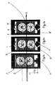
- Figures 1 to 4 shows the high-speed shears for cross-cutting of rolled strip with opposite pairs in rotation drivable knife carriers 1, 1 '.
- the knife carriers 1, 1 ' are on both sides in a common scissor cassette 2 stored at a fixed mutual distance, the scissor cassette 2 inside an outer frame 3 is arranged, and the scissor cassette 2 lifting means 4 assigned to raise or lower within the outer frame 3 are.
- lifting means 4 can either be arranged below the scissor cassette 2 be as shown in Figures 1 and 3, the lifting means the weight of the Scissor cartridge 2 overcome by pressure, or they can according 4a, 4b can be arranged above the outer frame 3, and the scissors cassette 2 lift under tension, which is equivalent in both cases Means.
- the scissors can be shown 1c means 5, 5 'for guiding the band 6 relative to the cutting position 7 be assigned.
- a pair of drivers 5, 5 ' be the band 6 at least in the cutting position 7 under tension hold.
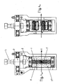
- each knife carrier 1, 1 ' as a rectangular body with a pair of long sides 8 and a pair of narrow sides 9 formed, each with two narrow sides 9 with one in the cutting position 7 knife arrangement 10, 10 'which can be formed together.
- Fig. 1d shows that the knife carrier 1, 1 'within the scissor cassette 2 by means of assigned to them, with each other in constant meshing gears 11, 11 'are synchronized in opposite rotation.
- the knife carriers 1, 1 ' are in the transfer position each raised with the scissors cassette 2, with the eccentric bushing 13 on its circular path 19 in the lower zenith of its circular path, and the eccentric bushing 13 'has reached its circular path 19' in the upper zenith, and the knife holder 1, 1 'take the greatest possible allowable distance between them.
- Figure 4a is a side view of the scissors with belt run 6 in the passage position and shown in Figure 4b in the cutting position.
- the two knife carriers are 1, 1 'when entering or running through a roll strip start with both knife carriers 1, 1 'in the horizontal position and with the scissor cassette 2 in the raised position brought into a transfer position within the outer frame 3, which it Band start allowed, even with the head bent like a ski through the Scissors to be passed through.
- the scissors start up under rotary acceleration Number of revolutions with knife carriers 1, 1 'placed at a distance from the scissors cassette 2 lowered with their bearings.
- the acceleration time for the start-up the scissors is due to the gear ratio between eccentric bushes 13, 13 'and knife carrier 1, 1' determined.
- the knife carrier 1, 1 ' is designed so that this an axial parallel displacement of, for example, +/- 15 mm.
- a synchronism of both knife carriers 1, 1 'less than 0.5 mm maintained becomes. Damage to the knife assemblies 10, 10 'is thereby avoided.
Abstract
Description
- Figur 1a
- die Schere mit angehobener Scherenkassette beim Ein- bzw. Durchlauf eines Walzbandanfangs mit beiden Messerträgem in Horizontalstellung;
- Figur 1b bis 1d
- einzelne Stellungsphasen der Messerträger bei ihrer rotativen Beschleunigung von Null auf Schnittdrehzahl;
- Figur 2
- ein kinematisches Schema des Antriebs der Messerträger mit ihren Wellenlagerungen in Exzenterbuchsen;
- Figur 3a bis 3c
- eine schematische Darstellung der Bewegungsabläufe der Messerträger und Exzenterbuchsen, ausgehend von der Überführstellung gemäß Fig. 3a bis zur Schneidposition in Fig. 3c;
- Figur 4a, 4b
- die Seitenansicht der Schere in Überführposition Fig. 4a, und in Schneidposition Fig. 4b.
- 1.
- Messerträger
- 2.
- Scherenkassette
- 3.
- äußerer Rahmen
- 4.
- Hubmittel
- 5.
- Mittel z. Führung des Bandes
- 6.
- Band
- 7.
- Schnittposition
- 8.
- Längsseite
- 9.
- Schmalseite
- 10.
- Messeranordnung
- 11.
- Zahnrad
- 12.
- Messerträgerwelle
- 13.
- Exzenterbuchse
- 14.
- Getriebe
- 15.
- Motor
- 16.
- Kupplung
- 17.
- Exzenterbuchsen-Antrieb
- 18.
- Drehrichtung Messerträger
- 19.
- Drehrichtung Exzenterbuchsen
Claims (13)
- Hochgeschwindigkeitsschere zum Querteilen von Walzband mit paarweise gegenüberliegenden, in Rotation antreibbaren Messerträgern,
dadurch gekennzeichnet,daß die Messerträger (1, 1') beidseitig in einer gemeinsamen Scherenkassette (2) mit festem gegenseitigem Abstand gelagert sind,daß die Scherenkassette (2) innerhalb eines äußeren Rahmens (3) angeordnet ist, unddaß der Scherenkassette (2) Hubmittel (4) zum Anheben bzw. Absenken innerhalb des äußeren Rahmens (3) zugeordnet sind. - Schere nach Anspruch 1,
dadurch gekennzeichnet,
daß ihr Mittel (5) zum Führen des Bandes (6) relativ zur Schnittposition (7) zugeordnet sind. - Schere nach Anspruch 1 oder 2,
daß jeder Messerträger (1, 1') als abgeflachter Körper mit einem Paar Längsseiten (8) und Schmalseiten (9) ausgebildet ist, und jeweils zwei Schmalseiten (9) mit in Schnittposition (7) zusammenwirkbaren Messeranordnungen (10) ausgebildet sind. - Schere nach einem oder mehreren der Ansprüche 1 bis 3,
dadurch gekennzeichnet,
daß die Messerträger (1, 1') innerhalb der Scherenkassette (2) mittels ihnen zugeordneten, miteinander im stetigen Eingriff befindlichen Zahnrädern (11, 11') in gegenläufiger Rotation synchronisiert sind. - Schere nach einem oder mehreren der Ansprüche 1 bis 4,
dadurch gekennzeichnet,
daß die Messerträgerwellen (12, 12') in Exzenterbuchsen (13, 13') gelagert sind, die über ein gemeinsames Getriebe (14) mit einem fest vorgegebenen Übersetzungsverhältnis zwischen den Exzenterbuchsen (13, 13') und den Messerträgerwellen (12, 12') angetrieben sind. - Verfahren zum Betrieb der Schere nach einem oder mehreren der Ansprüche 1 bis 5,
dadurch gekennzeichnet,
daß beim Ein- bzw. Durchlauf eines Walzbandendes die beiden Messerträger (1, 1') in Horizontalstellung und die Scherenkassette (2) innerhalb des äußeren Rahmens (3) in eine angehobene Überführstellung gebracht wird. - Verfahren nach Anspruch 6,
dadurch gekennzeichnet,
daß der Anlauf der Schere unter rotativer Beschleunigung der Umdrehungszahl vorgenommen wird, wobei die Messerträger (1, 1') über die Exzenterbuchsen (13, 13) auf Abstand gestellt sind und die Scherenkassette (2) mit ihren Lagerstücken abgesenkt wird. - Verfahren nach einem der Ansprüche 6 oder 7,
dadurch gekennzeichnet,
daß die Beschleunigungszeit für den Anlauf der Schere durch das Übersetzungsverhältnis zwischen Exzenterbuchsen (13, 13') und Messerträgem (1, 1') bestimmt wird. - Verfahren nach einem oder mehreren der Ansprüche 6 bis 8,
dadurch gekennzeichnet,
daß die Zahngeometrie der Synchronisationsräder der Messerträger (1, 1') so ausgelegt wird, daß diese eine Achsparallelverschiebung von beispielsweise +/- 15 mm zuläßt. - Verfahren nach einem oder mehreren der Ansprüche 6 bis 9,
dadurch gekennzeichnet,
daß für einen exakten Bogenschnitt bei geringer Banddicke, z. B. 0,8 mm, ein Gleichlauf beider Messerträger (1, 1') kleiner, 0,5 mm eingehalten wird. - Verfahren nach einem oder mehreren der Ansprüche 6 bis 10,
dadurch gekennzeichnet,
daß für die fliegende Schere bei einer Bandlaufgeschwindigkeit bis 20 m/sec zur Ausführung eines 2-Messer-Bogenschnitts exakt eingespannte Bogenmesser verwendet werden. - Verfahren nach einem oder mehreren der Ansprüche 6 bis 11,
dadurch gekennzeichnet,
daß das Band (6) zum Schnitt zwischen zwei Paaren von Treibern (5, 5') auf Zugspannung gehalten wird. - Verfahren nach einem oder mehreren der Ansprüche 6 bis 12,
dadurch gekennzeichnet,
daß die Exzenterbuchsen (13, 13') in eine zu den Messerträgem (1, 1') entgegengesetzte Rotation versetzt werden.
Applications Claiming Priority (2)
| Application Number | Priority Date | Filing Date | Title |
|---|---|---|---|
| DE10001928A DE10001928A1 (de) | 2000-01-19 | 2000-01-19 | Hochgeschwindigkeitsschere zum Querteilen von Walzband |
| DE10001928 | 2000-01-19 |
Publications (2)
| Publication Number | Publication Date |
|---|---|
| EP1118409A1 true EP1118409A1 (de) | 2001-07-25 |
| EP1118409B1 EP1118409B1 (de) | 2005-10-12 |
Family
ID=7627886
Family Applications (1)
| Application Number | Title | Priority Date | Filing Date |
|---|---|---|---|
| EP01100536A Expired - Lifetime EP1118409B1 (de) | 2000-01-19 | 2001-01-10 | Hochgeschwindigkeitsschere zum Querteilen von Walzband |
Country Status (9)
| Country | Link |
|---|---|
| US (1) | US20010020407A1 (de) |
| EP (1) | EP1118409B1 (de) |
| JP (1) | JP5232344B2 (de) |
| AT (1) | ATE306350T1 (de) |
| BR (1) | BR0100101A (de) |
| CA (1) | CA2330986C (de) |
| DE (2) | DE10001928A1 (de) |
| ES (1) | ES2249330T3 (de) |
| MX (1) | MXPA01000668A (de) |
Cited By (1)
| Publication number | Priority date | Publication date | Assignee | Title |
|---|---|---|---|---|
| US20040177734A1 (en) * | 2000-01-19 | 2004-09-16 | Horst Grafe | High-speed shear for transversely cutting rolled strip |
Families Citing this family (4)
| Publication number | Priority date | Publication date | Assignee | Title |
|---|---|---|---|---|
| DE19833324A1 (de) * | 1998-07-24 | 2000-01-27 | Schloemann Siemag Ag | Verfahren und Vorrichtung zum Querteilen von Bändern oder Blechen in der Walz- bzw. Transportlinie |
| AU2002357824A1 (en) | 2001-12-13 | 2003-06-30 | John R. Buta | Helical rotary drum shears |
| DE102010026607A1 (de) * | 2010-07-09 | 2012-01-12 | Gallus Druckmaschinen Gmbh | Vorrichtung zum rotativen Stanzen von flachem mehrschichtigem Gut |
| DE102017221764A1 (de) | 2017-12-04 | 2019-06-06 | Sms Group Gmbh | Vorrichtung und Verfahren zum Kühlen einer Querteilschere in Warmbandstraßen |
Citations (4)
| Publication number | Priority date | Publication date | Assignee | Title |
|---|---|---|---|---|
| DE464803C (de) * | 1926-03-04 | 1928-08-27 | Demag Akt Ges | Schere fuer in Bewegung befindliches Walzgut |
| US1948139A (en) * | 1931-08-17 | 1934-02-20 | United Eng Foundry Co | Rotary flying shear |
| EP0162020A1 (de) * | 1984-04-12 | 1985-11-21 | INNSE INNOCENTI SANTEUSTACCHIO S.p.A. | Verfahren und Vorrichtung zum Durchlassen dicker Bänder in eine rotierende Schere |
| EP0829322A1 (de) * | 1996-09-17 | 1998-03-18 | Sms Schloemann-Siemag Aktiengesellschaft | Hochgeschwindigkeitsschere zum Querteilen von Walzband |
Family Cites Families (2)
| Publication number | Priority date | Publication date | Assignee | Title |
|---|---|---|---|---|
| JP2993680B2 (ja) * | 1989-07-14 | 1999-12-20 | 株式会社日立製作所 | 剪断装置及び剪断方法、並びに、熱間圧延設備及び熱間圧延設備の圧延方法 |
| JP3347826B2 (ja) * | 1993-08-09 | 2002-11-20 | 石川島播磨重工業株式会社 | 切断設備及びその運転方法 |
-
2000
- 2000-01-19 DE DE10001928A patent/DE10001928A1/de not_active Withdrawn
-
2001
- 2001-01-05 US US09/755,869 patent/US20010020407A1/en not_active Abandoned
- 2001-01-10 ES ES01100536T patent/ES2249330T3/es not_active Expired - Lifetime
- 2001-01-10 AT AT01100536T patent/ATE306350T1/de active
- 2001-01-10 DE DE50107644T patent/DE50107644D1/de not_active Expired - Lifetime
- 2001-01-10 EP EP01100536A patent/EP1118409B1/de not_active Expired - Lifetime
- 2001-01-11 CA CA002330986A patent/CA2330986C/en not_active Expired - Fee Related
- 2001-01-17 JP JP2001008933A patent/JP5232344B2/ja not_active Expired - Lifetime
- 2001-01-18 BR BR0100101-9A patent/BR0100101A/pt not_active IP Right Cessation
- 2001-01-19 MX MXPA01000668A patent/MXPA01000668A/es active IP Right Grant
Patent Citations (4)
| Publication number | Priority date | Publication date | Assignee | Title |
|---|---|---|---|---|
| DE464803C (de) * | 1926-03-04 | 1928-08-27 | Demag Akt Ges | Schere fuer in Bewegung befindliches Walzgut |
| US1948139A (en) * | 1931-08-17 | 1934-02-20 | United Eng Foundry Co | Rotary flying shear |
| EP0162020A1 (de) * | 1984-04-12 | 1985-11-21 | INNSE INNOCENTI SANTEUSTACCHIO S.p.A. | Verfahren und Vorrichtung zum Durchlassen dicker Bänder in eine rotierende Schere |
| EP0829322A1 (de) * | 1996-09-17 | 1998-03-18 | Sms Schloemann-Siemag Aktiengesellschaft | Hochgeschwindigkeitsschere zum Querteilen von Walzband |
Cited By (2)
| Publication number | Priority date | Publication date | Assignee | Title |
|---|---|---|---|---|
| US20040177734A1 (en) * | 2000-01-19 | 2004-09-16 | Horst Grafe | High-speed shear for transversely cutting rolled strip |
| US8683898B2 (en) * | 2000-01-19 | 2014-04-01 | Sms Siemag Aktiengesellschaft | Method of operating a high-speed shear |
Also Published As
| Publication number | Publication date |
|---|---|
| JP5232344B2 (ja) | 2013-07-10 |
| US20010020407A1 (en) | 2001-09-13 |
| DE50107644D1 (de) | 2005-11-17 |
| JP2001239423A (ja) | 2001-09-04 |
| MXPA01000668A (es) | 2002-06-21 |
| ATE306350T1 (de) | 2005-10-15 |
| BR0100101A (pt) | 2001-08-28 |
| EP1118409B1 (de) | 2005-10-12 |
| CA2330986C (en) | 2008-07-08 |
| CA2330986A1 (en) | 2001-07-19 |
| ES2249330T3 (es) | 2006-04-01 |
| DE10001928A1 (de) | 2001-07-26 |
Similar Documents
| Publication | Publication Date | Title |
|---|---|---|
| EP0840672B1 (de) | Querschneider für eine warenbahn, insbesondere wellpappenbahn | |
| DE3900734C2 (de) | Vorrichtung zum Richten und Abschneiden von Runddraht oder dergleichen | |
| EP1099501B1 (de) | Hochgeschwindigkeitsschere zum Querteilen von Walzband | |
| EP0829322B1 (de) | Hochgeschwindigkeitsschere zum Querteilen von Walzband | |
| DE2335966A1 (de) | Verfahren und vorrichtung zum schlitzen von metallstreifen | |
| EP1118409B1 (de) | Hochgeschwindigkeitsschere zum Querteilen von Walzband | |
| DE3415438C2 (de) | Eindrückungsfreie Rohrschneidevorrichtung | |
| DE2604729A1 (de) | Verfahren und maschine zur schrumpf- folien-verpackung | |
| EP1099502B1 (de) | Hochgeschwindigkeitsschere zum Querteilen von insbesondere dünnem Walzband | |
| EP1566243B1 (de) | Vorrichtung zum Positionieren und Antreiben eines Arbeitswerkzeuges | |
| EP1068040B1 (de) | Hochgeschwindigkeitsschere zum querteilen von walzband | |
| DE3029143A1 (de) | Rotierende stanzvorrichtung | |
| DE19756622B4 (de) | Doppelprofilschnittmaschine mit Längsverschiebung der Profile | |
| DE2244747C3 (de) | Vorrichtung zum Querschneiden von Bahnen aus Papier od.dgl | |
| EP1166934B1 (de) | Hochgeschwindigkeitsschere mit einstellbaren Messertrommeln | |
| DE2935029B1 (de) | Verfahren zum Bewegen des oder der Brennschneidaggregate beim Brennschneiden und Vorrichtung hierfuer | |
| DE102019219309A1 (de) | Vorrichtung und Verfahren zum Querteilen eines Metallbandes in einer Walzstraße | |
| EP0510400B1 (de) | Trommelstanzschere | |
| DE4201245A1 (de) | Maschine fuer die bearbeitung von blechen und profilen | |
| EP0714720A1 (de) | Bearbeitungsmaschine mit Stanzeinrichtung und Einrichtung zur rollenden Werkstückbearbeitung | |
| EP1378306B1 (de) | Exzenterschere | |
| DE4420688C2 (de) | Verfahren und Vorrichtung zum Stanzen von kontinuierlich bewegtem Stanzgut | |
| EP3854506A1 (de) | Vorrichtung und verfahren zum querteilen eines metallbandes in einer walzstrasse | |
| DE102021210611A1 (de) | Schere und Verfahren zum Schneiden von Schneidgut | |
| DE202012005349U1 (de) | Querteilschere |
Legal Events
| Date | Code | Title | Description |
|---|---|---|---|
| PUAI | Public reference made under article 153(3) epc to a published international application that has entered the european phase |
Free format text: ORIGINAL CODE: 0009012 |
|
| 17P | Request for examination filed |
Effective date: 20010131 |
|
| AK | Designated contracting states |
Kind code of ref document: A1 Designated state(s): AT BE CH CY DE DK ES FI FR GB GR IE IT LI LU MC NL PT SE TR |
|
| AX | Request for extension of the european patent |
Free format text: AL;LT;LV;MK;RO;SI |
|
| AKX | Designation fees paid |
Free format text: AT BE CH CY DE DK ES FI FR GB GR IE IT LI LU MC NL PT SE TR |
|
| 17Q | First examination report despatched |
Effective date: 20041011 |
|
| GRAP | Despatch of communication of intention to grant a patent |
Free format text: ORIGINAL CODE: EPIDOSNIGR1 |
|
| RIN1 | Information on inventor provided before grant (corrected) |
Inventor name: MERZ, JUERGEN Inventor name: LOTH, VOLKER Inventor name: GRAFE, HORST |
|
| GRAS | Grant fee paid |
Free format text: ORIGINAL CODE: EPIDOSNIGR3 |
|
| GRAA | (expected) grant |
Free format text: ORIGINAL CODE: 0009210 |
|
| AK | Designated contracting states |
Kind code of ref document: B1 Designated state(s): AT BE CH CY DE DK ES FI FR GB GR IE IT LI LU MC NL PT SE TR |
|
| PG25 | Lapsed in a contracting state [announced via postgrant information from national office to epo] |
Ref country code: IE Free format text: LAPSE BECAUSE OF FAILURE TO SUBMIT A TRANSLATION OF THE DESCRIPTION OR TO PAY THE FEE WITHIN THE PRESCRIBED TIME-LIMIT Effective date: 20051012 |
|
| REG | Reference to a national code |
Ref country code: GB Ref legal event code: FG4D Free format text: NOT ENGLISH |
|
| REG | Reference to a national code |
Ref country code: CH Ref legal event code: EP |
|
| REG | Reference to a national code |
Ref country code: SE Ref legal event code: TRGR |
|
| REG | Reference to a national code |
Ref country code: IE Ref legal event code: FG4D Free format text: LANGUAGE OF EP DOCUMENT: GERMAN |
|
| REF | Corresponds to: |
Ref document number: 50107644 Country of ref document: DE Date of ref document: 20051117 Kind code of ref document: P |
|
| PG25 | Lapsed in a contracting state [announced via postgrant information from national office to epo] |
Ref country code: GR Free format text: LAPSE BECAUSE OF FAILURE TO SUBMIT A TRANSLATION OF THE DESCRIPTION OR TO PAY THE FEE WITHIN THE PRESCRIBED TIME-LIMIT Effective date: 20060112 Ref country code: DK Free format text: LAPSE BECAUSE OF FAILURE TO SUBMIT A TRANSLATION OF THE DESCRIPTION OR TO PAY THE FEE WITHIN THE PRESCRIBED TIME-LIMIT Effective date: 20060112 |
|
| PG25 | Lapsed in a contracting state [announced via postgrant information from national office to epo] |
Ref country code: CH Free format text: LAPSE BECAUSE OF NON-PAYMENT OF DUE FEES Effective date: 20060131 Ref country code: MC Free format text: LAPSE BECAUSE OF NON-PAYMENT OF DUE FEES Effective date: 20060131 Ref country code: LI Free format text: LAPSE BECAUSE OF NON-PAYMENT OF DUE FEES Effective date: 20060131 |
|
| GBT | Gb: translation of ep patent filed (gb section 77(6)(a)/1977) |
Effective date: 20060118 |
|
| PG25 | Lapsed in a contracting state [announced via postgrant information from national office to epo] |
Ref country code: PT Free format text: LAPSE BECAUSE OF FAILURE TO SUBMIT A TRANSLATION OF THE DESCRIPTION OR TO PAY THE FEE WITHIN THE PRESCRIBED TIME-LIMIT Effective date: 20060313 |
|
| REG | Reference to a national code |
Ref country code: ES Ref legal event code: FG2A Ref document number: 2249330 Country of ref document: ES Kind code of ref document: T3 |
|
| REG | Reference to a national code |
Ref country code: IE Ref legal event code: FD4D |
|
| ET | Fr: translation filed | ||
| PLBE | No opposition filed within time limit |
Free format text: ORIGINAL CODE: 0009261 |
|
| STAA | Information on the status of an ep patent application or granted ep patent |
Free format text: STATUS: NO OPPOSITION FILED WITHIN TIME LIMIT |
|
| REG | Reference to a national code |
Ref country code: CH Ref legal event code: PL |
|
| 26N | No opposition filed |
Effective date: 20060713 |
|
| PG25 | Lapsed in a contracting state [announced via postgrant information from national office to epo] |
Ref country code: CY Free format text: LAPSE BECAUSE OF FAILURE TO SUBMIT A TRANSLATION OF THE DESCRIPTION OR TO PAY THE FEE WITHIN THE PRESCRIBED TIME-LIMIT Effective date: 20051012 |
|
| PGFP | Annual fee paid to national office [announced via postgrant information from national office to epo] |
Ref country code: LU Payment date: 20130125 Year of fee payment: 13 |
|
| PGFP | Annual fee paid to national office [announced via postgrant information from national office to epo] |
Ref country code: GB Payment date: 20130122 Year of fee payment: 13 Ref country code: FI Payment date: 20130111 Year of fee payment: 13 Ref country code: SE Payment date: 20130122 Year of fee payment: 13 |
|
| PGFP | Annual fee paid to national office [announced via postgrant information from national office to epo] |
Ref country code: BE Payment date: 20130128 Year of fee payment: 13 |
|
| PGFP | Annual fee paid to national office [announced via postgrant information from national office to epo] |
Ref country code: NL Payment date: 20140121 Year of fee payment: 14 |
|
| PGFP | Annual fee paid to national office [announced via postgrant information from national office to epo] |
Ref country code: FR Payment date: 20140123 Year of fee payment: 14 Ref country code: ES Payment date: 20140129 Year of fee payment: 14 Ref country code: TR Payment date: 20140103 Year of fee payment: 14 |
|
| BERE | Be: lapsed |
Owner name: *SMS DEMAG A.G. Effective date: 20140131 |
|
| PG25 | Lapsed in a contracting state [announced via postgrant information from national office to epo] |
Ref country code: LU Free format text: LAPSE BECAUSE OF NON-PAYMENT OF DUE FEES Effective date: 20140110 |
|
| REG | Reference to a national code |
Ref country code: SE Ref legal event code: EUG |
|
| GBPC | Gb: european patent ceased through non-payment of renewal fee |
Effective date: 20140110 |
|
| PG25 | Lapsed in a contracting state [announced via postgrant information from national office to epo] |
Ref country code: FI Free format text: LAPSE BECAUSE OF NON-PAYMENT OF DUE FEES Effective date: 20140110 |
|
| PG25 | Lapsed in a contracting state [announced via postgrant information from national office to epo] |
Ref country code: GB Free format text: LAPSE BECAUSE OF NON-PAYMENT OF DUE FEES Effective date: 20140110 Ref country code: SE Free format text: LAPSE BECAUSE OF NON-PAYMENT OF DUE FEES Effective date: 20140111 |
|
| PG25 | Lapsed in a contracting state [announced via postgrant information from national office to epo] |
Ref country code: BE Free format text: LAPSE BECAUSE OF NON-PAYMENT OF DUE FEES Effective date: 20140131 |
|
| REG | Reference to a national code |
Ref country code: DE Ref legal event code: R082 Ref document number: 50107644 Country of ref document: DE Representative=s name: HEMMERICH & KOLLEGEN, DE Ref country code: DE Ref legal event code: R081 Ref document number: 50107644 Country of ref document: DE Owner name: SMS GROUP GMBH, DE Free format text: FORMER OWNER: SMS SIEMAG AKTIENGESELLSCHAFT, 40237 DUESSELDORF, DE |
|
| REG | Reference to a national code |
Ref country code: NL Ref legal event code: V1 Effective date: 20150801 |
|
| PG25 | Lapsed in a contracting state [announced via postgrant information from national office to epo] |
Ref country code: NL Free format text: LAPSE BECAUSE OF NON-PAYMENT OF DUE FEES Effective date: 20150801 |
|
| REG | Reference to a national code |
Ref country code: FR Ref legal event code: ST Effective date: 20150930 |
|
| PG25 | Lapsed in a contracting state [announced via postgrant information from national office to epo] |
Ref country code: FR Free format text: LAPSE BECAUSE OF NON-PAYMENT OF DUE FEES Effective date: 20150202 |
|
| REG | Reference to a national code |
Ref country code: ES Ref legal event code: FD2A Effective date: 20160229 |
|
| PG25 | Lapsed in a contracting state [announced via postgrant information from national office to epo] |
Ref country code: ES Free format text: LAPSE BECAUSE OF NON-PAYMENT OF DUE FEES Effective date: 20150111 |
|
| PG25 | Lapsed in a contracting state [announced via postgrant information from national office to epo] |
Ref country code: TR Free format text: LAPSE BECAUSE OF NON-PAYMENT OF DUE FEES Effective date: 20150110 |
|
| PGFP | Annual fee paid to national office [announced via postgrant information from national office to epo] |
Ref country code: DE Payment date: 20200121 Year of fee payment: 20 Ref country code: AT Payment date: 20200122 Year of fee payment: 20 Ref country code: IT Payment date: 20200131 Year of fee payment: 20 |
|
| REG | Reference to a national code |
Ref country code: DE Ref legal event code: R071 Ref document number: 50107644 Country of ref document: DE |
|
| REG | Reference to a national code |
Ref country code: AT Ref legal event code: MK07 Ref document number: 306350 Country of ref document: AT Kind code of ref document: T Effective date: 20210110 |