EP1116882A2 - Compresseur à capacité variable et climatisation - Google Patents
Compresseur à capacité variable et climatisation Download PDFInfo
- Publication number
- EP1116882A2 EP1116882A2 EP20010100664 EP01100664A EP1116882A2 EP 1116882 A2 EP1116882 A2 EP 1116882A2 EP 20010100664 EP20010100664 EP 20010100664 EP 01100664 A EP01100664 A EP 01100664A EP 1116882 A2 EP1116882 A2 EP 1116882A2
- Authority
- EP
- European Patent Office
- Prior art keywords
- displacement
- compressor
- value
- pressure
- duty ratio
- Prior art date
- Legal status (The legal status is an assumption and is not a legal conclusion. Google has not performed a legal analysis and makes no representation as to the accuracy of the status listed.)
- Withdrawn
Links
Images


Classifications
-
- F—MECHANICAL ENGINEERING; LIGHTING; HEATING; WEAPONS; BLASTING
- F04—POSITIVE - DISPLACEMENT MACHINES FOR LIQUIDS; PUMPS FOR LIQUIDS OR ELASTIC FLUIDS
- F04B—POSITIVE-DISPLACEMENT MACHINES FOR LIQUIDS; PUMPS
- F04B27/00—Multi-cylinder pumps specially adapted for elastic fluids and characterised by number or arrangement of cylinders
- F04B27/08—Multi-cylinder pumps specially adapted for elastic fluids and characterised by number or arrangement of cylinders having cylinders coaxial with, or parallel or inclined to, main shaft axis
- F04B27/14—Control
- F04B27/16—Control of pumps with stationary cylinders
- F04B27/18—Control of pumps with stationary cylinders by varying the relative positions of a swash plate and a cylinder block
- F04B27/1804—Controlled by crankcase pressure
-
- F—MECHANICAL ENGINEERING; LIGHTING; HEATING; WEAPONS; BLASTING
- F04—POSITIVE - DISPLACEMENT MACHINES FOR LIQUIDS; PUMPS FOR LIQUIDS OR ELASTIC FLUIDS
- F04B—POSITIVE-DISPLACEMENT MACHINES FOR LIQUIDS; PUMPS
- F04B49/00—Control, e.g. of pump delivery, or pump pressure of, or safety measures for, machines, pumps, or pumping installations, not otherwise provided for, or of interest apart from, groups F04B1/00 - F04B47/00
- F04B49/06—Control using electricity
- F04B49/065—Control using electricity and making use of computers
-
- F—MECHANICAL ENGINEERING; LIGHTING; HEATING; WEAPONS; BLASTING
- F04—POSITIVE - DISPLACEMENT MACHINES FOR LIQUIDS; PUMPS FOR LIQUIDS OR ELASTIC FLUIDS
- F04B—POSITIVE-DISPLACEMENT MACHINES FOR LIQUIDS; PUMPS
- F04B27/00—Multi-cylinder pumps specially adapted for elastic fluids and characterised by number or arrangement of cylinders
- F04B27/08—Multi-cylinder pumps specially adapted for elastic fluids and characterised by number or arrangement of cylinders having cylinders coaxial with, or parallel or inclined to, main shaft axis
- F04B27/14—Control
- F04B27/16—Control of pumps with stationary cylinders
- F04B27/18—Control of pumps with stationary cylinders by varying the relative positions of a swash plate and a cylinder block
- F04B27/1804—Controlled by crankcase pressure
- F04B2027/1809—Controlled pressure
- F04B2027/1813—Crankcase pressure
-
- F—MECHANICAL ENGINEERING; LIGHTING; HEATING; WEAPONS; BLASTING
- F04—POSITIVE - DISPLACEMENT MACHINES FOR LIQUIDS; PUMPS FOR LIQUIDS OR ELASTIC FLUIDS
- F04B—POSITIVE-DISPLACEMENT MACHINES FOR LIQUIDS; PUMPS
- F04B27/00—Multi-cylinder pumps specially adapted for elastic fluids and characterised by number or arrangement of cylinders
- F04B27/08—Multi-cylinder pumps specially adapted for elastic fluids and characterised by number or arrangement of cylinders having cylinders coaxial with, or parallel or inclined to, main shaft axis
- F04B27/14—Control
- F04B27/16—Control of pumps with stationary cylinders
- F04B27/18—Control of pumps with stationary cylinders by varying the relative positions of a swash plate and a cylinder block
- F04B27/1804—Controlled by crankcase pressure
- F04B2027/1822—Valve-controlled fluid connection
- F04B2027/1827—Valve-controlled fluid connection between crankcase and discharge chamber
-
- F—MECHANICAL ENGINEERING; LIGHTING; HEATING; WEAPONS; BLASTING
- F04—POSITIVE - DISPLACEMENT MACHINES FOR LIQUIDS; PUMPS FOR LIQUIDS OR ELASTIC FLUIDS
- F04B—POSITIVE-DISPLACEMENT MACHINES FOR LIQUIDS; PUMPS
- F04B27/00—Multi-cylinder pumps specially adapted for elastic fluids and characterised by number or arrangement of cylinders
- F04B27/08—Multi-cylinder pumps specially adapted for elastic fluids and characterised by number or arrangement of cylinders having cylinders coaxial with, or parallel or inclined to, main shaft axis
- F04B27/14—Control
- F04B27/16—Control of pumps with stationary cylinders
- F04B27/18—Control of pumps with stationary cylinders by varying the relative positions of a swash plate and a cylinder block
- F04B27/1804—Controlled by crankcase pressure
- F04B2027/184—Valve controlling parameter
- F04B2027/1854—External parameters
-
- F—MECHANICAL ENGINEERING; LIGHTING; HEATING; WEAPONS; BLASTING
- F04—POSITIVE - DISPLACEMENT MACHINES FOR LIQUIDS; PUMPS FOR LIQUIDS OR ELASTIC FLUIDS
- F04B—POSITIVE-DISPLACEMENT MACHINES FOR LIQUIDS; PUMPS
- F04B2205/00—Fluid parameters
- F04B2205/07—Pressure difference over the pump
-
- Y—GENERAL TAGGING OF NEW TECHNOLOGICAL DEVELOPMENTS; GENERAL TAGGING OF CROSS-SECTIONAL TECHNOLOGIES SPANNING OVER SEVERAL SECTIONS OF THE IPC; TECHNICAL SUBJECTS COVERED BY FORMER USPC CROSS-REFERENCE ART COLLECTIONS [XRACs] AND DIGESTS
- Y10—TECHNICAL SUBJECTS COVERED BY FORMER USPC
- Y10T—TECHNICAL SUBJECTS COVERED BY FORMER US CLASSIFICATION
- Y10T137/00—Fluid handling
- Y10T137/7722—Line condition change responsive valves
- Y10T137/7758—Pilot or servo controlled
- Y10T137/7761—Electrically actuated valve
Definitions
- the present invention relates to variable displacement compressors varying displacement in a range from- minimum to maximum and air conditioning apparatuses incorporating the compressors.
- a typical air conditioning apparatus for vehicles has a refrigerant circuit including a condenser, a pressure reducing device (for example, an expansion valve), an evaporator, and a compressor.
- the compressor recently adopted is often a variable displacement compressor (particularly, a swash plate type variable displacement compressor) that is flexible to meet various air-conditioning requirements.
- a prior-art swash plate type variable displacement compressor varies its displacement by maintaining the pressure acting on an evaporator outlet (suction pressure Ps) at a predetermined target value (target suction pressure). That is, the compressor has a displacement control valve that controls the compressor displacement in a feedback manner in accordance with the suction pressure Ps, which serves as a reference indicator, such that the displacement corresponds to the cooling load of the compressor.
- a pressure sensitive member such as a bellows or a diaphragm, detects the suction pressure Ps.
- the movement of the pressure sensitive member positions a valve body to adjust the opening size of the control valve.
- This varies the pressure (crank pressure Pc) in a swash plate chamber (crank chamber) to alter an inclination angle of the swash plate. That is, the piston stroke is varied in accordance with the inclination angle of the swash plate, which is controlled in a range from a minimum inclination angle ⁇ min to a maximum inclination angle Omax.
- the compressor displacement is thus adjusted as necessary in a range from minimum to a maximum.
- COP coefficient of performance
- Q indicates refrigerating performance (heat absorbing performance of the evaporator)
- L indicates the power supplied to the compressor (workload of the compressor).
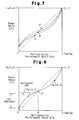
- Fig. 7 is a graph in which refrigerating performance ratio (Q/Q 0 ) is plotted along the horizontal axis (X-axis) and power ratio (L/L 0 ) is plotted along the vertical axis (Y-axis).
- Q/Q 0 L/L 0 .
- the graph includes three curves.
- the curves indicate characteristics of the swash plate type variable displacement compressor operated under different conditions regarding the suction pressure Ps and the like. The conditions are varied among the curves.
- each curve crosses the diagonal straight line at a point P (referred to as the "points of divergence").
- points of divergence In an area of the power ratio located above each point P, as viewed in the graph, corresponding sections of the curves are located below the diagonal line. These sections of the curves thus indicate a relative increase in the COP, as compared to the maximum performance COP.
- corresponding sections of the curve are located above the diagonal line.
- the lower operational efficiency during the relatively small displacement operation is caused by the following: (a) a reduced piston stroke decreases the sealing effect between the outer surface of each piston and the inner wall of the corresponding cylinder bore, thus increasing gas leakage from the cylinder bore to the crank chamber; (b) a greater amount of gas must be supplied to the crank chamber from the discharge chamber to maintain the crank pressure Pc at a relatively high level during lower displacement operation, and the amount of waste gas is increased; and (c) the proportion of mechanical power loss caused by friction for moving movable parts including the swash plate is increased during lower displacement operation.
- variable displacement compressor the operational efficiency of which is improved by avoiding operation under conditions that reduce operational efficiency, and an air conditioning apparatus employing this variable displacement compressor.
- the present invention is a variable displacement compressor that varies the displacement in a variation range including a minimum displacement and a maximum displacement.
- the compressor includes an acquiring device for acquiring a target value used for controlling the compressor displacement, a switching device, which compares the target value with a predetermined reference value and switches an operational mode in accordance with a result from the comparison such that the displacement corresponding to the target value achieves a coefficient of performance equal to or greater than a predetermined level, and an actuator for varying the displacement in accordance with an instruction from at least the switching device.
- the air conditioning apparatus has a refrigerant circuit (refrigerating circuit) including a swash plate type variable displacement compressor CM and an external refrigerant circuit 30.
- the external refrigerant circuit 30 has, for example, a condenser 31, an expansion valve 32, which is a pressure reducing device, an evaporator 33, a refrigerant passage 35, and a refrigerant passage 36.
- the passage 35 connects an outlet of the evaporator 33 to a suction chamber 21 of the compressor CM
- the passage 36 connects a discharge chamber 22 of the compressor CM to an inlet of the condenser 31.
- Refrigerant gas is supplied to the suction chamber 21 from the evaporator 33 through the passage 35.
- the compressor CM draws the refrigerant gas from the suction chamber 21 and compresses the gas.
- the compressed gas is sent to the discharge chamber 22.
- the high-pressure gas in the discharge chamber 22 is then supplied to the condenser 31 through the passage 36.
- the expansion valve 32 internally controls its opening size in a feedback manner in accordance with the temperature and pressure of refrigerant gas, which are detected by a sensor 34 located in the vicinity of the outlet of the evaporator 33.
- the amount of the refrigerant gas supplied from the condenser 31 to the evaporator 33 thus corresponds to cooling load of the compressor CM. In this manner, the amount of the refrigerant flowing in the external refrigerant circuit 30 is directly adjusted.
- the swash plate type variable displacement compressor CM includes a cylinder block 1, a front housing member 2, and a rear housing member 4.
- the front housing member 2 is secured to a front end of the cylinder block 1, which is the left end in Fig. 2.
- the rear housing member 4 is connected to a rear end of the cylinder block 1 with a valve plate 3 provided between the rear housing member 4 and the cylinder block 1.
- the cylinder block 1, the front housing member 2, the valve plate 3, and the rear housing member 4 form a housing of the compressor CM.
- a crank chamber 5 is formed in the housing.
- a drive shaft 6 extends through the crank chamber 5 and is rotationally supported by the housing.
- a lug plate 11 is secured to the drive shaft 6 and rotates integrally with the drive shaft 6.
- the drive shaft 6 and the lug plate 11, which are integrally connected to each other, are urged toward the front housing member 2 by a spring 7 and positioned in thrust direction.
- the drive shaft 6 has a front end connected to an external drive source, which is an engine E of a vehicle in this embodiment, through a power transmitting mechanism PT.
- the power transmitting mechanism PT is a clutchless mechanism that transmits power constantly (for example, a combination of a belt and a pulley).
- a cam plate, which is a swash plate 12 in this embodiment, is accommodated in the crank chamber 5.
- the swash plate 12 is operationally connected to the lug plate 11 and the drive shaft 6 by means of a hinge mechanism 13.
- the hinge mechanism 13 includes a pair of support arms 14 (only one is shown in Fig. 2) and a pair of guide pins 15 (only one is shown in Fig. 2).
- Each support arm 14 projects from a rear side of the lug plate 11, and each guide pin 15 projects from a front side of the swash plate 12.
- the support arms 14 cooperate with the associated guide pins 15.
- the drive shaft 6 extends through a through hole formed in the swash plate 12 and contacts with the swash plate 12 by way of the through hole. Accordingly, the swash plate 12 rotates integrally with the lug plate 11 and the drive shaft 6 through the engagement by hinge mechanism 13 and the contact in the through hole. Further, the swash plate 12 inclines with respect to the drive shaft 6 while sliding axially along the drive shaft 6.
- An inclination angle reducing spring 16 is provided around the drive shaft 6 and extends between the lug plate 11 and the swash plate 12.
- the spring 16 urges the swash plate 12 toward the cylinder block 1 for decreasing the inclination angle of the swash plate 12.
- a return spring 17 is provided around the drive shaft 6 and extends between the swash plate 12 and a restriction ring 18 secured to the drive shaft 6.
- the spring 17 does not affect the swash plate 12.
- the return spring 17 is compressed between the swash plate 12 and the restriction ring 18. The spring 17 thus urges the swash plate 12 away from the cylinder block 1.
- a plurality of cylinder bores la are formed in the cylinder block 1. Each cylinder bore la accommodates a single-headed piston 20, and the piston 20 moves in the cylinder bore la. A front end of each piston 20 is connected to the outer periphery of the swash plate 12 through a pair of shoes 19. The shoes 19 connect the piston 20 to the swash plate 12. Thus, when the swash plate 12 rotates integrally with the drive shaft 6, the rotation of the swash plate 12 is converted to linear movement of each piston 20. The stroke of the piston 20 corresponds to the inclination angle ⁇ of the swash plate 12.
- a suction chamber 21 and a discharge chamber 22 are formed by the valve plate 3 and the rear housing member 4. The suction chamber 21 is encompassed by the discharge chamber 22.
- the valve plate 3 includes suction ports 23, suction valves 24 selectively opening and closing the associated suction ports 23, discharge ports 25, and discharge valves 26 selectively opening and closing the associated discharge ports 25.
- Each cylinder bore la corresponds to one suction port 23 and the associated suction valve 24 as well as one discharge port 25 and the associated discharge valve 26.
- the refrigerant gas in the suction chamber 21 (a zone in which the suction pressure Ps acts), which is introduced from the outlet of the evaporator 33, is drawn to the cylinder bore la through the suction port 23 opened by the associated suction valve 24.
- the refrigerant gas in the cylinder bore la is then compressed to a predetermined pressure when the piston 20 moves from its top dead center to its bottom dead center.
- the compressed gas is discharged from the cylinder bore la to the discharge chamber 22 (a zone in which the discharge pressure Pd acts) through the discharge port 25 opened by the associated discharge valve 26.
- the swash plate 12 is rotated as inclined by an angle ⁇ .
- the angle ⁇ is defined as an angle formed between a hypothetical plane extending perpendicular to the axis of the drive shaft 6 and the swash plate 12.
- each piston 20 is moved by a stroke corresponding to the inclination angle ⁇ of the swash plate 12.
- the pistons 20 repeatedly perform the above operation, which is drawing refrigerant gas to the cylinder bores la, compression of the gas, and discharge of the gas from the cylinder bores la.
- the inclination angle ⁇ is determined according to the equilibrium of various moments including a rotation moment caused by centrifugal force generated by the swash plate 12, a moment caused by the force of the spring 16 (and the spring 17), a moment caused by the force of inertia generated by reciprocating movement of each piston 20, and a gas pressure moment.
- the gas pressure moment is generated in accordance with the pressure in each cylinder bore la and the pressure in the crank chamber 5 (crank pressure Pc), which act on opposite sides of the piton 20.
- crank pressure Pc the pressure in accordance with the crank pressure Pc.
- the crank pressure Pc is adjusted by the displacement control valve, which will be described later, thus altering the gas pressure moment.
- the maximum inclination angle ⁇ max is mechanically determined by a counterweight 12a of the swash plate 12 abutting against a restricting portion 11a of the lug plate 11.
- the minimum inclination angle ⁇ min is determined in accordance with the force of the spring 16 and the force of the return spring 17 acting against the spring 16 when the gas pressure moment is substantially maximized in the direction in which the inclination angle is decreased.
- the inclination angle ⁇ of the swash plate 12 is thus controlled in accordance with the crank pressure Pc.
- a mechanism for controlling the crank pressure Pc is formed by a bleed passage 27 and a supply passage 28, which both extend in the housing of the compressor, and the control valve CV, which is an actuator.
- the bleed passage 27 connects the suction chamber 21 to the crank chamber 5.
- the supply passage 28 connects the discharge chamber 22 to the crank chamber 5.
- the control valve CV is provided in the supply passage 28.
- the amount of high-pressure gas supplied to the crank chamber 5 through the supply passage 28 is altered by adjusting the opening size of the control valve CV.
- the crank pressure Pc is determined in accordance with the amount of gas supplied through the supply passage 28 into the crank chamber 5 and the amount of gas released through the bleed passage 27 from the crank chamber 5.
- crank pressure Pc is altered, the difference between the pressure in each cylinder bore la and the crank pressure Pc, which act on opposite sides of the associated piston 20, is also changed.
- the inclination angle ⁇ of the swash plate 12 is thus altered to vary the piston stroke, or the compressor displacement.
- the pressure loss per unit length of the circuit, or refrigerant passage is increased. More specifically, as the refrigerant flow rate in the refrigerant circuit increases, the pressure loss (pressure difference) between a pair of pressure monitoring points P1, P2 located along the refrigerant circuit increases.
- the compressor displacement is detected indirectly by determining the pressure difference ⁇ P(t) between the points P1 and P2.
- an upstream pressure monitoring point P1 is located in the discharge chamber 22, which is a most upstream section of the passage 36.
- a downstream pressure monitoring point P2 is located in the passage 36 at a position spaced from the point P1 at a predetermined distance.
- the gas pressure PdH detected at the point P1 (the discharge pressure Pd) is introduced to the control valve CV via a first passage 37.
- the gas pressure PdL detected at the point P2 is introduced to the control valve CV via a second passage 38.
- the control valve CV adjusts its opening size in accordance with the detected pressure difference ⁇ P(t), thus executing a feedback control procedure for the compressor displacement.
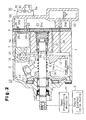
- the control valve CV includes an inlet valve portion located in an upper section of the valve CV and a solenoid portion 60 located in a lower section of the valve CV.
- the inlet valve portion adjusts the opening size (restriction size) of the supply passage 28 connecting the discharge chamber 22 to the crank chamber 5.
- the solenoid portion 60 is an electromagnetic urging mechanism that urges a movable rod 40 located in the control valve CV in accordance with an external, electric control signal.
- the movable rod 40 includes a distal portion 41, which receives the pressure difference ⁇ P(t), a connecting portion 42, a valve body 43, which is located substantially in the middle of the rod 40, and a guide rod section 44, which forms a proximal portion of the rod 40.
- the valve body 43 forms part of the guide rod section 44.
- the cross-sectional area of the distal portion 41 is defined as SB, that of the connecting portion 42 is defined as SC, and that of the guide rod section 44 (including the valve body 43) is defined as SD.
- SC cross-sectional area of the distal portion 41
- SC that of the connecting portion 42
- SD that of the guide rod section 44 (including the valve body 43)
- SC that of the guide rod section 44 (including the valve body 43)
- a valve housing 45 of the control valve CV includes a lid 45a, an upper body section 45b, which substantially forms the contour of the inlet valve portion, and a lower body section 45c, which forms the contour of the solenoid portion 60.
- a valve chamber 46 and a communication passage 47 are formed in the upper body section 45b.
- a pressure sensitive chamber 48 is formed by the upper body section 45b and a lid 45a that is secured to an upper portion of the section 45b, as viewed in Fig. 3.
- the movable rod 40 extends through the valve chamber 46, the communication passage 47, and the pressure sensitive chamber 48 and moves in an axial direction (the vertical direction as viewed in Fig. 3).
- the valve chamber 46 is connected with the communication passage 47 when the rod 40 is located at a certain position.
- the communication passage 47 is blocked from the pressure sensitive chamber 48 by a partition (forming part of the valve housing 45) located between the passage 47 and the chamber 48.
- a guide hole 49 is formed in the partition for guiding the rod 40, and the diameter of the guide hole 49 is equal to the diameter of the distal portion 41 of the rod 40.
- the communication passage 47 is formed by the guide hole 49, and the diameter of the communication passage 47 is equal to the diameter of the distal portion 41.
- the valve chamber 46 has a bottom formed by an upper side of a fixed iron core 62, which will be described later.
- a port 51 extends radially through a wall section of the valve housing encompassing the valve chamber 46.
- the port 51 connects the discharge chamber 22 to the valve chamber 46 through an upstream section of the supply passage 28.
- a port 52 extends radially through a wall section of the valve housing encompassing the communication passage 47.
- the port 52 connects the communication passage 47 to the crank chamber 5 through a downstream section of the supply passage 28.
- the valve chamber 46 accommodates the valve body 43 of the movable rod 40.
- the diameter of the communication passage 47 is larger than the diameter of the connecting portion 42 of the rod 40 but smaller than the diameter of the guide rod section 44.
- a step between the valve chamber 46 and the communication passage 47 thus forms a valve seat 53, and the communication passage 47 functions as a valve hole. If the movable rod 40 is moved from the position of Fig. 3 (lowermost position) to an uppermost position at which the valve body 43 is received by the valve seat 53, the communication passage 47 is closed.
- the valve body 43 of the movable rod 40 functions as an inlet valve body that adjusts the opening size of the supply passage 28 to a desired degree.
- a movable wall 54 is provided in the pressure sensitive chamber 48 and moves axially in the chamber 48.
- the movable wall 54 axially divides the pressure sensitive chamber 48 into a pair of sections, which are a P1 pressure chamber (first pressure chamber) 55 and a P2 pressure chamber (second pressure chamber) 56.
- the movable wall 54 moves in accordance with the pressure difference between the P1 pressure chamber 55 and the P2 pressure chamber 56.
- the cross-sectional area of the movable wall 54 is defined as SA and is larger than the cross-sectional area SB of the communication passage 47 or the guide hole 49 (SB ⁇ SA).
- the P1 pressure chamber 55 is constantly connected to the discharge chamber 22 and the upstream pressure monitoring point P1 through the first passage 37.
- the P2 pressure chamber 56 is constantly connected to the downstream pressure monitoring point P2 through the second passage 38. That is, the discharge pressure Pd is applied to the P1 pressure chamber 55 and is referred to as the pressure PdH.
- the pressure PdL acting on the point P2 is applied to the P2 pressure chamber 56. Accordingly, an upper side of the movable wall 54 is exposed to the pressure PdH, and a lower side of the wall 54 is exposed to the pressure PdL, as viewed in Fig. 3.
- the distal portion 41 of the movable rod 40 projects into the P2 pressure chamber 56.
- the movable wall 54 is secured to a distal end of the distal portion 41.
- a buffer spring 57 is located in the P2 pressure chamber 56 for urging the movable wall 54 toward the P1 pressure chamber 55.
- the solenoid portion 60 of the control valve CV includes an accommodating cylinder 61 having a closed end.
- the fixed iron core 62 is fitted in an upper section of the cylinder 61 to define a solenoid chamber 63 in the cylinder 61.
- the solenoid chamber 63 accommodates a movable iron core 64, which is also referred to as a plunger.
- the movable core 64 moves axially in the solenoid chamber 63.
- a guide hole 65 extends axially in the middle of the fixed core 62.
- the guide hole 65 receives the guide rod section 44 of the movable rod 40, which moves axially in the guide hole 65.
- a slight clearance, or a slit 65a is formed between the wall of the guide hole 65 and the guide rod section 44.
- a valve chamber 46 is connected to the solenoid chamber 63 through the slit 65a. That is, the solenoid chamber 63 is exposed to the discharge pressure Pd, which also acts in the valve chamber 46.
- the solenoid chamber 63 receives the proximal portion of the movable rod 40.
- a proximal end of the guide rod section 44 extends in the solenoid chamber 63. This end of the guide rod section 44 is securely fitted in a hole formed in the middle of the movable core 64 through crimping. The movable rod 40 thus moves integrally with the movable core 64.
- a return spring 66 is provided between the fixed core 62 and the movable core 64.
- the return spring 66 urges the movable core 64 away from the fixed core 62, thus pressing the movable core 64 and the movable rod 40 downward, as viewed in Fig. 3.
- the force f2 of the return spring 66 is greater than the force fl of the buffer spring 57.
- the return spring 66 thus acts to return the movable core 64 and the movable rod 40 to a lowermost position (an initial position when current supply is nullified).
- a coil 67 is wound around the fixed core 62 and the movable core 64. The coil 67 is supplied with a drive signal sent from a driver 71 in response to an instruction of a controller 70.
- the coil 67 generates electromagnetic force F corresponding to current supply from the driver 71.
- the electromagnetic force F draws the movable core 64 toward the fixed core 62, thus moving the movable rod 40 toward the P1 pressure chamber 55.
- the current supply to the coil 67 may be determined by an analog current control procedure or a duty control procedure, in which a duty ratio Dt of the drive signal is altered as needed. In this embodiment, the duty control procedure is employed.
- the opening size of the control valve CV increases as the duty ratio Dt of the drive signal decreases. That is, the opening size of the control valve CV decreases as the duty ratio Dt of the drive signal increases.
- the opening size of the control valve CV is determined in accordance with the position of the movable rod 40, which forms the valve body 43.
- the operational conditions and characteristics of the control valve CV are made clear by analyzing various forces acting on the movable rod 40.
- the upper side of the distal portion 41 of the rod 40 receives a downward force generated in accordance with the pressure difference between the points P1, P2 and diminished by the upward force fl of the buffer spring 57.
- the pressure receiving area of the upper side of the movable wall 54 is SA
- the pressure receiving area of the lower side of the movable wall 54 is SA-SB.
- a lower side of the distal portion 41 receives an upward force caused by the crank pressure Pc.
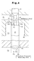
- Pressures acting on the valve body 43, the guide rod section 44, and the movable core 64 will hereafter be analyzed with reference to Fig. 4, which schematically shows pressures acting on the movable rod 40. As shown in Fig.
- an imaginary cylindrical surface extending axially from the wall of the communication passage 47 divides the upper side of the valve body 43 into a radially inner section and a radially outer section.
- the crank pressure Pc acts downward on the inner section (the area of which is SB-SC), and the discharge pressure Pd acts downward on the outer section (the area of which is SD-SB), as viewed in Fig. 4. Since the pressure acting on the upper side of the movable core 64 is equilibrated with the pressure applied to the lower side of the movable core 64, the discharge pressure Pd, to which the solenoid chamber 63 is exposed, urges the guide rod section 44 upward at an area corresponding to the cross-sectional area SD of the guide rod section 44. Further, as shown in Fig. 3, the guide rod section 44 of the movable rod 40 (including the valve body 43) receives the upward electromagnetic force F and the downward force f2 of the return spring 66, which acts against the electromagnetic force F.
- the effective pressure receiving area of the guide rod section 44 corresponds to the cross sectional area SB of the communication passage 47, regardless of the cross sectional area SD of the guide rod section 44.
- the term "effective pressure receiving area" is defined as the pressure receiving area of one side of the member that has an uncanceled effect.
- f1, f2, SA, and SB are definite parameters that are determined when designing the control valve, while the electromagnetic force F is varied in accordance with the current supply to the coil 67.
- the equation (3) thus indicates the following two points. Firstly, the control valve CV determines a target value for the pressure difference ⁇ P(t) between the points p1 and P2 (PdH-PdL), or a target pressure difference TPD in relation to which the control valve CV adjusts its opening.
- the target value can be changed by an external duty control procedure for the coil 67. In other words, the control valve CV is externally controlled to alter the target pressure difference TPD.
- the target pressure difference TPD is determined by the solenoid portion 60, the buffer spring 57, and the return spring 66, as indicated by (F+f1-f2) in the equation (3).
- the condition that the movable rod 40 is positioned to satisfy, or the equation (3), does not include pressure parameters (such as Pc and Pd) other than the pressure difference between the points P1 and P2 (PdH-PdL).
- the movable rod 40 is thus positioned regardless of the absolute value of the crank pressure Pc and that of the discharge pressure Pd. That is, pressure parameters other than the pressure difference between the points P1 and P2 (PdH-PdL) do not affect movement of the movable rod 40.
- the control valve CV is thus smoothly operated only in accordance with the pressure difference ⁇ P(t) between the points P1 and P2, the electromagnetic force F, the spring force fl, and the spring force f2.
- control valve CV functions as a constant flow valve that determines the target pressure difference TPD in accordance with the current electromagnetic force F.
- the control valve CV functions as a variable displacement control valve.
- the air conditioning apparatus includes the controller 70 that controls the air conditioning apparatus as a whole.
- the controller 70 is a computer-like control unit having a central processing unit (CPU), a read-only memory (ROM), a random-access memory (RAM), and an input/output interface (I/O interface).
- the driver 71 is connected to an output terminal of the I/O interface, and an external information acquiring device 72 is connected to an input terminal of the I/O interface.
- the controller 70 operates to determine the target duty ratio and to switch the operational mode of the compressor. More specifically, the controller 70 computes a tentative duty ratio DtP (corresponding to a "target duty ratio") and a final duty ratio Dt in accordance with at least various external information supplied by the external information acquiring device 72.
- the controller 70 performs an internal computation based on the tentative duty ratio DtP and outputs the final duty ratio Dt to the driver 71. That is, the controller 70 instructs the driver 71 to send a drive signal with the final duty ratio Dt to the coil 67.
- the electromagnetic force F of the solenoid portion 60 is altered in accordance with the duty ratio Dt of the drive signal supplied to the coil 67.
- the target pressure difference TPD according to which the control valve CV internally adjusts its opening size, is varied in accordance with the duty ratio Dt.
- the external information acquiring device 72 includes various sensors such as an A/C switch 73, a temperature sensor 74, a temperature adjuster 75, a vehicle speed sensor 76, an engine speed sensor 77, and an accelerator position sensor 78.
- the A/C switch 73 is an ON/OFF switch manipulated by a driver or passenger to turn on and off the air conditioning apparatus.
- the temperature sensor 74 detects the passenger compartment temperature Te(t) (or the temperature of the air exiting from the evaporator, which is varied in relation to the passenger compartment temperature).
- the temperature adjuster 75 sets a desired temperature Te(set) for the passenger compartment (or the air exiting from the evaporator).
- the vehicle speed sensor 76 detects the vehicle speed
- the engine speed sensor 77 detects the engine speed.
- the accelerator position sensor 78 detects the opening size of a throttle valve provided in an engine intake manifold. The opening size of the throttle valve reflects the position of the accelerator, which is depressed by the driver.
- the controller 70 executes a duty ratio control procedure for the control valve CV, as will hereafter be described with reference to the flowcharts of Figs. 5 and 6.
- the flowchart of Fig. 5 shows a main routine of an air conditioning control program.
- the controller 70 When the ignition switch (or START switch) of the vehicle is turned on, the controller 70 is powered to initiate computation.
- step S51 (hereinafter referred to simply as "S51", and other steps are referred to in the same manner), the controller 70 executes various initial settings in accordance with an initial program. For example, the tentative duty ratio DtP and the final duty ratio Dt are each set to a tentative value or an initial value.
- the controller 70 monitors the operational state of the vehicle and internally computes a duty ratio.
- the controller 70 monitors the ON/OFF state of the A/C switch 73.
- the controller 70 initiates an exceptional state determining routine (S53).
- the controller 70 judges whether the vehicle is operating in an exceptional state, or an exceptional mode, in accordance with the external information.
- the term "exceptional mode" indicates a state in which the vehicle, for example, is climbing a slope, which applies an increased load to the engine E.
- the term also indicates a state in which the vehicle is accelerated for, for example, when passing another vehicle (or at least the driver is rapidly accelerating the vehicle).
- the controller 70 acquires the detected accelerator position from the external information acquiring device 72 and compares the value with a predetermined reference value. In this manner, the controller 70 determines that the vehicle is operating in the increased load state or the accelerated state (the exceptional state).
- the controller 70 performs an exceptional state control procedure (S54). More specifically, the controller 70 maintains the final duty ratio Dt at zero or a minimum duty ratio Dt(min) during a predetermined time period ⁇ t after detecting the exceptinal state.
- the control valve CV is fully opened ( maximum opening size), regardless of the pressure difference (PdH-PdL) between the points P1 and P2.
- the crank pressure Pc is thus rapidly increased, and the inclination angle ⁇ is quickly minimized to minimize the compressor displacement. This reduces the load acting on the engine E, and makes additional engine power available for driving the vehicle.
- the cooling performance of the air conditioning apparatus is temporarily lowered during the time period ⁇ t, which is relatively short, passenger' comfort is not significantly sacrificed in most cases.
- the judgement of S53 becomes negative. In this case, it is determined that the vehicle is operating in a normal state, or a normal operational mode.
- the term "normal operational mode" indicates a state in which any judgement conditions for the non-normal state determining routine are not satisfied and it is assumed that the vehicle is operated in a normal state.
- the controller 70 initiates a normal state control routine RF6. In many cases, the controller 70 first performs the normal state control routine RF6 and then resumes S52 of the main routine of Fig. 5.
- the controller 70 executes a feedback control procedure for the air conditioning performance, or the compressor displacement, in accordance with the normal state control routine RF6.
- the control valve CV which includes the movable wall 54 that is exposed to the pressure difference ⁇ P(t), adjusts its opening size mechanically or internally in accordance with variation in the pressure difference ⁇ P(t) (PdH-PdL).
- the controller 70 corrects the target pressure difference TPD of the control valve CV in relation to the thermal load currently acting on the evaporator 33.
- the controller 70 regressively corrects the tentative duty ratio DtP for the internal computation and determines the final duty ratio Dt, which is sent to the driver 71, in accordance with the corrected tentative duty ratio DtP.
- the controller 70 judges whether the temperature Te(t) detected by the temperature sensor 74 exceeds the target temperature Te(set) set by the temperature adjuster 75. If the judgement of S61 is negative, the controller 70 judges whether the detected temperature Te(t) is lower than the target temperature Te(set) in S62. If the judgement of S62 is also negative, it is indicated that the detected temperature Te(t) is equal to the target temperature Te(set). In this case, the cooling performance of the compressor need not be corrected, and the tentative duty ratio DtP remains unchanged.
- the controller 70 increases the tentative duty ratio DtP by a unit amount ⁇ D in S63.
- the duty ratio of the drive signal is altered to the increased value (DtP+ ⁇ D)
- the electromagnetic force F generated by the solenoid portion 60 is increased accordingly, thus increasing the target pressure difference TPD of the control valve CV.
- the force resulting from current pressure difference ⁇ P(t) does not equilibrate the upward urging force and the downward urging force acting on the movable rod 40.
- the movable rod 40 is thus moved toward the P1 pressure chamber 55 such that the downward force f2 of the return spring 66 matches the increased upward electromagnetic force F.
- valve body 43 of the movable rod 40 is repositioned to satisfy the equation (3).
- the difference between the crank pressure Pc and the pressure in the cylinder bore la, which act on opposite sides of the piston 20 decreases to increase the inclination angle of the swash plate 12.
- the cooling performance of the evaporator 33 is improved , which lowers the passenger compartment temperature Te(t).
- the pressure difference ⁇ P(t) between the pressure monitoring points P1 and P2 is increased.
- the opening size of the control valve CV is then reversely mechanically increased in a feedback manner.
- the controller 70 reduces the tentative duty ratio DtP by a unit amount ⁇ D in S64.
- the duty ratio of the drive signal is altered to the decreased value (DtP- ⁇ D)
- the electromagnetic force F generated by the solenoid portion 60 is reduced accordingly, thus decreasing the target pressure difference TPD of the control valve CV.
- the force resulting from the current pressure difference ⁇ P(t) does not equilibrate the upward urging force and the downward urging force acting on the movable rod 40.
- the movable rod 40 is thus moved away from the P1 pressure chamber 55 such that the downward force f2 of the return spring 66 matches the decreased upward electromagnetic force F. Accordingly, the valve body 43 of the movable rod 40 is repositioned to satisfy the equation (3).
- This increases the opening size of the control valve CV (the supply passage 28) accordingly, thus raising the crank pressure Pc.
- the difference between the crank pressure Pc and the pressure in the cylinder bore la, which act on opposite sides of the piston 20 increases to decrease the inclination angle of the swash plate 12. This reduces the compressor displacement, thus decreasing the load acting on the engine.
- the cooling performance of the evaporator 33 is decreased, which increases the passenger compartment temperature Te(t). In this state, the pressure difference ⁇ P(t) between the pressure monitoring points P1 and P2 is decreased.
- the opening size of the control valve CV is then reversely mechanically reduced in a feedback manner.
- the controller 70 corrects the tentative duty ratio DtP in S63 and/or S64. This gradually optimizes the target pressure difference TPD of the control valve CV.
- the control valve CV thus internally adjusts its opening size in a feedback manner in accordance with the target pressure difference TPD. In this manner, the detected temperature Te(t) approaches the target temperature Te(set).
- the controller 70 performs a procedure for restricting an upper limit of the tentative duty ratio DtP, after terminating S62, S63, or 564. This prevents the tentative duty ratio DtP from exceeding the maximum value Dt(max) of an acceptable variation range for the final duty ratio Dt. More specifically, the controller 70 judges whether the tentative duty ratio DtP is larger than the maximum duty ratio Dt(max) in S65. If the judgement of S65 is positive, the controller 70 reduces the tentative duty ratio DtP to the maximum duty ratio Dt(max) in S66. Accordingly, once the controller 70 terminates S65 or S66, the tentative duty ratio DtP is always equal to or smaller than the maximum duty ratio Dt(max).
- the controller 70 judges whether the tentative duty ratio DtP is equal to or larger than a predetermined reference value DJ in S67. If the judgement of S67 is positive, the coefficient of performance COP obtained with the displacement corresponding to this tentative duty ratio DtP is satisfactory. That is, the reference value DJ indirectly indicates a displacement corresponding to a minimum value of a desired coefficient of performance, which is a threshold value of displacement (how to set the value DJ will be described later). Thus, if the judgement of S67 is positive, the tentative duty ratio DtP is selected as the final duty ratio Dt (see S68). In this case, in the subsequent step S610, the controller 70 instructs the driver 71 to send a drive signal representing the final duty ratio Dt to the coil 67.
- the tentative duty ratio DtP for the internal computation is smaller than the reference value DJ, the current supply to the coil 67 is substantially nullified.
- the compressor displacement is varied continuously as long as a relatively high coefficient of performance COP is ensured. However, if the COP is likely to be relatively low, the compressor displacement is minimized, regardless of the tentative duty ratio for the internal computation. More specifically, the compressor operation is switched between a variable displacement operation and a minimum displacement operation based on the comparison between the tentative duty ratio DtP and the reference value DJ. Selection of the reference value DJ will hereafter be described by way of example.
- Fig. 8 is a graph like to the graph of Fig. 7, but Figure 8 includes only one curve representing the operational characteristics of the compressor.
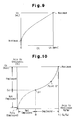
- Fig. 9 is a graph showing the relationship between the actual duty ratio (the final duty ratio Dt) of the drive signal, which is sent to the coil 67, and the compressor displacement Vc. Since the power L required by the compressor increases as the displacement Vc increases, the graph of Fig. 9 also shows the relationship between the final duty ratio Dt and the power L indirectly. As shown in Fig. 9, although not linearly, the final duty ratio Dt is increased as the displacement Vc, or the power L, is increased. Considering this relationship between the duty ratio Dt and the power L, the vertical axis (y-axis) of Fig.
- the refrigerating performance ratio (Q/Q 0 ) is plotted along the horizontal axis and the final duty ratio Dt is plotted along the axis.
- the graph includes a curve having a single-dotted broken section and a solid section. The broken section is connected to the solid section by a point of inflection P'.
- the refrigerating performance ratio corresponding to the point P' is defined as B.
- the point of divergence P corresponds to the refrigerating performance ratio defined as B.
- the final duty ratio (DJ) corresponding to the point of inflection P' of Fig. 10 is selected as the reference value DJ, which is used for the judgement of S67. More specifically, if the final duty ratio Dt is equal to the value DJ, the corresponding refrigerating performance ratio is B. As shown in Fig. 8, the COP corresponding to the refrigerating performance ratio B is the value indicated by the point P. As in the graph of Fig. 7, in an area below the point P of Fig. 8, or an area in which the displacement is lower than a value corresponding to the point P (indicated by the dotted area in Fig. 8), the COP is relatively low.
- the power ratio is not nullified even when the refrigerating performance ratio is nullified.
- this point of the curve is located relatively close to the diagonal line, although included in the dotted area, as compared to the point C, which is relatively spaced from the line.
- the COP corresponding to the minimum displacement is still relatively close to the value Q 0 /L 0 as compared to the COP corresponding to the point C, or higher than the COP corresponding to the point C. Accordingly, in order to ensure a relatively high COP, or a relatively high efficiency, it is advantageous to minimize the displacement if the operational state corresponds to the area below the point P of Fig. 8.
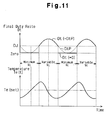
- Fig. 11 is a timing chart (in which curves are simplified for convenience of understanding) showing the variation of the final duty ratio Dt and the detected temperature Te(t) during the normal control routine of Fig. 6 performed when the target temperature Te (set) is maintained at a constant level.
- a period in which the final duty ratio Dt is zero alternates with a period in which the final duty ratio Dt is equal to or greater than the reference value DJ.
- the displacement Vc of the compressor is variably controlled.
- the detected temperature Te(t) increases when the displacement Vc is maintained at minimum. However, if the variable control of the displacement Vc is resumed, the detected temperature Te(t) starts to decrease with a relatively short delay. However, the detected temperature Te(t) starts to increase again, toward the target temperature Te(set), without decreasing excessively. In this manner, the passenger compartment temperature is steered foward the target temperature Te(set) though is has slight fluctuation and varies in a relatively small range around the target value Te(set).
- This embodiment has the following effects.
- the tentative duty ratio DtP for the internal computation of the controller 70 is considered to be a parameter that indirectly indicates the compressor displacement Vc, or the refrigerant flow in the refrigerant circuit.
- DJ coefficient of performance
- the compressor operation is switched between the minimum displacement operation and the variable displacement operation. That is, the variable control of the displacement is avoided when the COP is likely to decrease below a minimum acceptable level (in this embodiment, Q 0 /L 0 ). This improves the operation efficiency of the compressor and that of the air conditioning apparatus.
- the compressor displacement is controlled in a feedback manner by directly controlling the pressure difference ⁇ P(t) between the points P1 and P2 (PdH-PdL). Accordingly, regardless of the thermal load acting on the evaporator 33, the displacement is decreased quickly and reliably in response to an external control procedure , as needed when the engine is in the exceptional state.
- the tentative duty ratio DtP for determining the target pressure difference TPD is automatically adjusted in relation to the detected temperature Te(t) and the target temperature Te(set). Further, the control valve internally adjusts its opening size in accordance with the pressure difference ⁇ P(t) between the points P1 and P2. This controls the compressor displacement. In other words, the air conditioning apparatus adjusts the compressor displacement to reduce the difference between the detected temperature Te(t) and the target temperature Te(set), to make the passenger compartment comfortable.
- the present invention may be modified as follows.
- the reference value DJ on which the compressor operation of switching between the minimum displacement operation and the variable displacement operation, is based, is a predetermined value (a fixed value).
- the reference value DJ may be varied during the control procedure.
- the reference value DJ may be corrected in accordance with external information including the engine speed, the flow rate of air through the evaporator, the atmospheric temperature, and the insolation amount. The judgement of S67 is performed in accordance with the corrected reference value DJ.
- the reference value DJ may be any value corresponding to a final duty ratio Dt that achieves an intermediate compressor displacement Vc that divides a displacement variation range into a large displacement area and a small displacement area.
- the reference value DJ may be any value, as long as the COP corresponding to the value DJ is considered to be a minimum acceptable COP.
- the variable controlling of the displacement is suspended when necessary to avoid a COP lower than the minimum acceptable COP, thus satisfying the objective of the present invention.
- the compressor displacement is varied continuously by altering the target pressure difference TPD of the control valve CV.
- the compressor may be operated by a predetermined fixed displacement corresponding to a predetermined COP, for example, a fixed displacement corresponding to the COP indicated by the point D of Fig. 8. That is, the duty ratio is fixed to a value corresponding to the point D' of Fig. 10, which corresponds to the point D.
- the final duty ratio Dt of the drive signal is switched between two values, which are zero and the value corresponding to the point D'. This still suppresses variable displacement operation in a relatively small displacement area, when COP is relatively low.
- the two pressure monitoring points P1 and P2 are located along the passage 36 connecting the discharge chamber 22 of the compressor to the condenser 31.
- the points P1 and P2 may be located along the passage 35 connecting the evaporator 33 to the suction chamber 21 of the compressor.
- the upstream point P1 may be located in the discharge chamber 22 or the passage 36, and the downstream point P2 may be located in the suction chamber 21 or the passage 35.
- the point P1 may be located in the discharge chamber 22 or the passage 36, and the point P2 may be located in the crank chamber 5.
- the point P1 may be located in the crank chamber 5, and the point P2 may be located in the suction chamber 21 or the passage 35.
- the pressure difference ⁇ P(t) between the points P1 and P2 reflects the amount of the refrigerant flowing in the refrigerant circuit, or the compressor displacement.
- the present invention may be applied to a variable displacement compressor to which power is transmitted from an engine E through a power transmitting mechanism PT having a clutch such as an electromagnetic clutch.
- the controller 70 minimizes the compressor displacement, regardless of the tentative duty ratio DtP, and disconnects the clutch if the tentative duty ratio DtP is smaller than the reference value DJ.
- the controller 70 disconnects the clutch immediately if the tentative duty ratio DtP is smaller than the reference value DJ, instead of minimizing the compressor displacement. That is, if it is assumed that the COP of the compressor is likely to drop, the power supply to the compressor is stopped by disconnecting the clutch.
- the present invention may be applied to a prior-art variable displacement compressor that varies its displacement in accordance with suction pressure.
- the term "refrigerant circuit” indicates, as shown in Fig. 1, the circuit including the condenser 31, the expansion valve 32, the evaporator 33, and the compressor (including the suction chamber 21, the cylinder bores la, and the discharge chamber 22).
- the cylinder bore la which performs suction, compression, and discharge of refrigerant gas, forms part of the refrigerant circuit.
- variable displacement compressor An efficient operation of a variable displacement compressor is maintained by avoiding a condition leading to a relatively low efficiency.
- the compressor varies its displacement using a control valve for which an external duty control procedure is performed.
Landscapes
- Engineering & Computer Science (AREA)
- Mechanical Engineering (AREA)
- General Engineering & Computer Science (AREA)
- Computer Hardware Design (AREA)
- Compressors, Vaccum Pumps And Other Relevant Systems (AREA)
- Air Conditioning Control Device (AREA)
- Control Of Positive-Displacement Pumps (AREA)
- Air-Conditioning For Vehicles (AREA)
Applications Claiming Priority (2)
| Application Number | Priority Date | Filing Date | Title |
|---|---|---|---|
| JP2000006800 | 2000-01-14 | ||
| JP2000006800A JP2001191789A (ja) | 2000-01-14 | 2000-01-14 | 容量可変型圧縮機および空調装置 |
Publications (2)
| Publication Number | Publication Date |
|---|---|
| EP1116882A2 true EP1116882A2 (fr) | 2001-07-18 |
| EP1116882A3 EP1116882A3 (fr) | 2003-08-13 |
Family
ID=18535273
Family Applications (1)
| Application Number | Title | Priority Date | Filing Date |
|---|---|---|---|
| EP20010100664 Withdrawn EP1116882A3 (fr) | 2000-01-14 | 2001-01-11 | Compresseur à capacité variable et climatisation |
Country Status (3)
| Country | Link |
|---|---|
| US (1) | US6537037B2 (fr) |
| EP (1) | EP1116882A3 (fr) |
| JP (1) | JP2001191789A (fr) |
Cited By (1)
| Publication number | Priority date | Publication date | Assignee | Title |
|---|---|---|---|---|
| EP1788246A1 (fr) * | 2005-11-16 | 2007-05-23 | Kabushiki Kaisha Toyota Jidoshokki | Compresseur à déplacement variable comprenant un appareil de réglage pour un système de refrigération de véhicule, et une valve de réglage |
Families Citing this family (14)
| Publication number | Priority date | Publication date | Assignee | Title |
|---|---|---|---|---|
| JP3735512B2 (ja) * | 2000-05-10 | 2006-01-18 | 株式会社豊田自動織機 | 容量可変型圧縮機の制御弁 |
| JP4081965B2 (ja) * | 2000-07-07 | 2008-04-30 | 株式会社豊田自動織機 | 容量可変型圧縮機の容量制御機構 |
| JP2002285956A (ja) * | 2000-08-07 | 2002-10-03 | Toyota Industries Corp | 容量可変型圧縮機の制御弁 |
| JP2002081374A (ja) * | 2000-09-05 | 2002-03-22 | Toyota Industries Corp | 容量可変型圧縮機の制御弁 |
| JP2002089442A (ja) * | 2000-09-08 | 2002-03-27 | Toyota Industries Corp | 容量可変型圧縮機の制御弁 |
| JP2002155858A (ja) * | 2000-09-08 | 2002-05-31 | Toyota Industries Corp | 容量可変型圧縮機の制御弁 |
| JP4333047B2 (ja) * | 2001-01-12 | 2009-09-16 | 株式会社豊田自動織機 | 容量可変型圧縮機の制御弁 |
| JP2004144462A (ja) * | 2002-08-26 | 2004-05-20 | Tgk Co Ltd | 冷凍サイクルの運転方法 |
| JP2006306320A (ja) * | 2005-04-28 | 2006-11-09 | Calsonic Kansei Corp | 車両用空調装置 |
| JP2007106260A (ja) * | 2005-10-13 | 2007-04-26 | Denso Corp | 車両用空調装置 |
| US7878214B1 (en) * | 2006-08-10 | 2011-02-01 | Jansen's Aircraft Systems Controls, Inc. | Ullage pressure regulator |
| JP5177864B2 (ja) * | 2008-06-04 | 2013-04-10 | 株式会社フジキン | 熱式質量流量調整器用自動圧力調整器 |
| JP5475501B2 (ja) * | 2010-02-24 | 2014-04-16 | サンデン株式会社 | 車両用空調装置 |
| JP5859299B2 (ja) * | 2011-12-15 | 2016-02-10 | 株式会社ヴァレオジャパン | 圧縮機の駆動トルク推定装置及びこれに用いる凝縮器 |
Citations (3)
| Publication number | Priority date | Publication date | Assignee | Title |
|---|---|---|---|---|
| US5685160A (en) * | 1994-09-09 | 1997-11-11 | Mercedes-Benz Ag | Method for operating an air conditioning cooling system for vehicles and a cooling system for carrying out the method |
| EP0952344A2 (fr) * | 1998-04-16 | 1999-10-27 | Kabushiki Kaisha Toyoda Jidoshokki Seisakusho | Soupape de contrÔle de débit d'un compresseur à capacité variable pour réfrigérant |
| EP0952412A2 (fr) * | 1998-04-16 | 1999-10-27 | Kabushiki Kaisha Toyoda Jidoshokki Seisakusho | Système frigorifique et procédé pour son fonctionnement |
Family Cites Families (8)
| Publication number | Priority date | Publication date | Assignee | Title |
|---|---|---|---|---|
| JP2551416B2 (ja) * | 1986-10-07 | 1996-11-06 | 株式会社ゼクセル | 自動車用空調装置 |
| JP2567947B2 (ja) * | 1989-06-16 | 1996-12-25 | 株式会社豊田自動織機製作所 | 可変容量圧縮機 |
| US5117643A (en) * | 1990-01-24 | 1992-06-02 | Zexel Corp. | Automobile air-conditioner |
| JPH07189899A (ja) | 1993-12-27 | 1995-07-28 | Toyota Autom Loom Works Ltd | 可変容量圧縮機 |
| US5702235A (en) * | 1995-10-31 | 1997-12-30 | Tgk Company, Ltd. | Capacity control device for valiable-capacity compressor |
| US6010312A (en) * | 1996-07-31 | 2000-01-04 | Kabushiki Kaisha Toyoda Jidoshokki Seiksakusho | Control valve unit with independently operable valve mechanisms for variable displacement compressor |
| JP3585150B2 (ja) * | 1997-01-21 | 2004-11-04 | 株式会社豊田自動織機 | 可変容量圧縮機用制御弁 |
| JP2000158939A (ja) * | 1998-11-24 | 2000-06-13 | Toyota Autom Loom Works Ltd | 車輌用空調装置及びその制御方法 |
-
2000
- 2000-01-14 JP JP2000006800A patent/JP2001191789A/ja active Pending
-
2001
- 2001-01-11 EP EP20010100664 patent/EP1116882A3/fr not_active Withdrawn
- 2001-01-12 US US09/760,352 patent/US6537037B2/en not_active Expired - Fee Related
Patent Citations (3)
| Publication number | Priority date | Publication date | Assignee | Title |
|---|---|---|---|---|
| US5685160A (en) * | 1994-09-09 | 1997-11-11 | Mercedes-Benz Ag | Method for operating an air conditioning cooling system for vehicles and a cooling system for carrying out the method |
| EP0952344A2 (fr) * | 1998-04-16 | 1999-10-27 | Kabushiki Kaisha Toyoda Jidoshokki Seisakusho | Soupape de contrÔle de débit d'un compresseur à capacité variable pour réfrigérant |
| EP0952412A2 (fr) * | 1998-04-16 | 1999-10-27 | Kabushiki Kaisha Toyoda Jidoshokki Seisakusho | Système frigorifique et procédé pour son fonctionnement |
Cited By (1)
| Publication number | Priority date | Publication date | Assignee | Title |
|---|---|---|---|---|
| EP1788246A1 (fr) * | 2005-11-16 | 2007-05-23 | Kabushiki Kaisha Toyota Jidoshokki | Compresseur à déplacement variable comprenant un appareil de réglage pour un système de refrigération de véhicule, et une valve de réglage |
Also Published As
| Publication number | Publication date |
|---|---|
| US6537037B2 (en) | 2003-03-25 |
| US20010014287A1 (en) | 2001-08-16 |
| JP2001191789A (ja) | 2001-07-17 |
| EP1116882A3 (fr) | 2003-08-13 |
Similar Documents
| Publication | Publication Date | Title |
|---|---|---|
| EP1127721B1 (fr) | Appareil et procédé de réglage du déplacement d'un compresseur à déplacement variable et module de compresseur | |
| US6371734B1 (en) | Control valve for variable displacement compressor | |
| US6481225B2 (en) | Air conditioning apparatus for vehicle and its control method | |
| JP3941303B2 (ja) | 空調装置 | |
| JP3731434B2 (ja) | 容量可変型圧縮機の制御弁 | |
| US6389824B2 (en) | Controller for variable displacement compressor | |
| US20010013225A1 (en) | Displacement control apparatus and method for variable displacement compressor | |
| US6537037B2 (en) | Variable displacement compressor and air conditioning apparatus | |
| US6508071B2 (en) | Air conditioner and displacement control valve for variable displacement compressor | |
| EP1095804A2 (fr) | Système de climatisation | |
| US6519960B2 (en) | Air conditioner | |
| US6524077B2 (en) | Control valve for variable displacement compressor | |
| EP1253033A2 (fr) | Climatiseur de véhicule et procédé de contrôle d'un climatiseur de véhicule | |
| US20040045305A1 (en) | Air conditioner | |
| US6647737B2 (en) | Air conditioner | |
| US6520749B2 (en) | Control valve for variable displacement compressor | |
| US7243502B2 (en) | Control system for variable displacement compressor | |
| US6510702B2 (en) | Control valve for variable displacement compressor |
Legal Events
| Date | Code | Title | Description |
|---|---|---|---|
| PUAI | Public reference made under article 153(3) epc to a published international application that has entered the european phase |
Free format text: ORIGINAL CODE: 0009012 |
|
| 17P | Request for examination filed |
Effective date: 20010111 |
|
| AK | Designated contracting states |
Kind code of ref document: A2 Designated state(s): AT BE CH CY DE DK ES FI FR GB GR IE IT LI LU MC NL PT SE TR |
|
| AX | Request for extension of the european patent |
Free format text: AL;LT;LV;MK;RO;SI |
|
| RAP1 | Party data changed (applicant data changed or rights of an application transferred) |
Owner name: KABUSHIKI KAISHA TOYOTA JIDOSHOKKI |
|
| PUAL | Search report despatched |
Free format text: ORIGINAL CODE: 0009013 |
|
| AK | Designated contracting states |
Designated state(s): AT BE CH CY DE DK ES FI FR GB GR IE IT LI LU MC NL PT SE TR |
|
| AX | Request for extension of the european patent |
Extension state: AL LT LV MK RO SI |
|
| AKX | Designation fees paid |
Designated state(s): DE FR IT |
|
| STAA | Information on the status of an ep patent application or granted ep patent |
Free format text: STATUS: THE APPLICATION IS DEEMED TO BE WITHDRAWN |
|
| 18D | Application deemed to be withdrawn |
Effective date: 20060801 |