EP1116477A1 - Chirurgische Werkzeugstation - Google Patents
Chirurgische Werkzeugstation Download PDFInfo
- Publication number
- EP1116477A1 EP1116477A1 EP00120737A EP00120737A EP1116477A1 EP 1116477 A1 EP1116477 A1 EP 1116477A1 EP 00120737 A EP00120737 A EP 00120737A EP 00120737 A EP00120737 A EP 00120737A EP 1116477 A1 EP1116477 A1 EP 1116477A1
- Authority
- EP
- European Patent Office
- Prior art keywords
- tool
- switch
- selector switch
- station according
- tools
- Prior art date
- Legal status (The legal status is an assumption and is not a legal conclusion. Google has not performed a legal analysis and makes no representation as to the accuracy of the status listed.)
- Granted
Links
Images





Classifications
-
- A—HUMAN NECESSITIES
- A61—MEDICAL OR VETERINARY SCIENCE; HYGIENE
- A61B—DIAGNOSIS; SURGERY; IDENTIFICATION
- A61B17/00—Surgical instruments, devices or methods
-
- A—HUMAN NECESSITIES
- A61—MEDICAL OR VETERINARY SCIENCE; HYGIENE
- A61B—DIAGNOSIS; SURGERY; IDENTIFICATION
- A61B17/00—Surgical instruments, devices or methods
- A61B2017/00017—Electrical control of surgical instruments
- A61B2017/00199—Electrical control of surgical instruments with a console, e.g. a control panel with a display
-
- A—HUMAN NECESSITIES
- A61—MEDICAL OR VETERINARY SCIENCE; HYGIENE
- A61B—DIAGNOSIS; SURGERY; IDENTIFICATION
- A61B17/00—Surgical instruments, devices or methods
- A61B2017/00367—Details of actuation of instruments, e.g. relations between pushing buttons, or the like, and activation of the tool, working tip, or the like
- A61B2017/00371—Multiple actuation, e.g. pushing of two buttons, or two working tips becoming operational
- A61B2017/00384—Actuation of one tool by pushing two buttons simultaneously
-
- A—HUMAN NECESSITIES
- A61—MEDICAL OR VETERINARY SCIENCE; HYGIENE
- A61B—DIAGNOSIS; SURGERY; IDENTIFICATION
- A61B17/00—Surgical instruments, devices or methods
- A61B2017/00973—Surgical instruments, devices or methods pedal-operated
-
- A—HUMAN NECESSITIES
- A61—MEDICAL OR VETERINARY SCIENCE; HYGIENE
- A61B—DIAGNOSIS; SURGERY; IDENTIFICATION
- A61B18/00—Surgical instruments, devices or methods for transferring non-mechanical forms of energy to or from the body
- A61B2018/0091—Handpieces of the surgical instrument or device
- A61B2018/00916—Handpieces of the surgical instrument or device with means for switching or controlling the main function of the instrument or device
- A61B2018/00922—Handpieces of the surgical instrument or device with means for switching or controlling the main function of the instrument or device by switching or controlling the treatment energy directly within the hand-piece
Definitions
- the invention relates to a surgical tool station according to the preamble of claim 1.
- FIG. 9 schematically shows such a known surgical tool station 12 next to an operating table 10.
- the tool station 12 shown has four Tools 14, 16 on.
- the tools operated with auxiliary energy include, for example Laser scalpels 16, but also those that are electric, pneumatic or are driven by flexible shafts 20, such as circular and jigsaws, Milling, punching, grinding plates, drills, belt and drill grinders.
- the known surgical tool station 12 also points to each tool 14, 16 is a separate foot switch 26 for switching this tool on and off 14, 16 on.
- the various foot switches 26 are under the operating table 10 arranged. Therefore, the surgeon, if in the manner shown in FIG. 9 is shown, the foot switch 26 no longer bends over the operating table 10 see, so there is a risk that he will mix up the footswitch 26 and accidentally does not switch on the tool 16 that he is currently holding in his hand 32, but turns on one of the other tools 14, which he just does not need. This can result in serious injuries if, for example, the assistant Sister cleans one of these tools 14 that is not currently required and the surgeon accidentally turns it on.
- a particular tool can only be operated with the main switch be switched on if the selector switch is operated in such a way that that particular tool is selected. Since there is only one main switch is, the surgeon can fully focus on his work and the immediate Concentrate around the attachment point of the tool he is currently using. The risk to assistants due to confusion various foot switches have been eliminated.
- each tool has its own selector switch, which has a non-contact proximity sensor with a detection element works together.
- This recognition element is preferred attached to the surgeon's hand holding the tool. If he is one takes certain tool in this hand, then there is the recognition element in the response range of the proximity sensor, causing the selector switch to this tool is operated and the control unit this selected tool releases. When the surgeon puts this tool down and for example handed over to the assistant nurse, then the recognition element comes off the response range of the proximity sensor, which makes the selector switch this Tool is switched and the control unit blocks this tool.
- the proximity sensor can be of the inductive type, for example.
- the detection element is electrically conductive to the inductive proximity sensor to be able to influence when approaching as desired.
- the recognition element can be, for example, a metal ring that the surgeon has on a finger or the Wrist of his hand holding the tools, or a metal plaque be glued to the back of the hand of the hand guiding the tools or is attached to the disposable glove for that hand.
- the assisting sisters, who also take the tools in hand must have no electrically conductive objects on their hands, so excluded can accidentally release a tool.
- the detection element has a transmitter for radiation of a characteristic signal and the proximity sensor a receiver for the Has identification signal.
- the proximity sensor is a transmitter for the emission of an interrogation signal and the detection element a transponder which is designed such that it only emits the identification signal, when he receives the interrogation signal.
- the selector switch is arranged on the control unit, and that each tool has a signal lamp that is only activated by the control unit is controlled when the tool assigned to it by the selector switch is selected.
- the desired tool is selected by that, for example, the assistant nurse operates the selector switch. She therefore has a direct impact on her own safety, as it is in her own It is of interest to only then select the tool desired by the surgeon or to release it when she has given it to him.
- the signal light serves her as feedback that she chose the right tool.
- each tool has its own selector switch has, which is arranged in the handle region of the tool. This selector switch is therefore operated when the surgeon has the tool properly in place Hand holding. For security reasons, care should then be taken to ensure that the assisting sister in handling this tool takes care that the Avoid grip area and especially the selector switch.
- the selector switch can be, for example, a push button or a light barrier.
- the main switch is preferably a foot switch.
- FIG. 1 shows an operating table 10 and a surgical tool station 12, the four tools 14, 16 operated with auxiliary energy, a switch arrangement for selective switching on and off of tools 14, 16 and a control unit 18 has.
- the tools comprise three driven by flexible shafts 20
- Tools 14, which are, for example, a milling machine, a circular saw and a drill, and a laser scalpel 16, which is connected to the laser source via an optical fiber cable 22 (not shown) is connected.
- the switch arrangement has a rotary switch 24 with five locking positions on the housing of the control unit 18 is attached, and a foot switch 26 on.
- the foot switch 26 is like this arranged below the operating table 10 that a surgeon can comfortably do this can operate when he bends over the operating table 10.
- the foot switch 26 is connected to the control unit 18 via a cable 28.
- the rotary switch 24 serves as a selector switch for selecting one of the tools 14, 16.
- the rotary switch 24 is in this way with the control unit 18 connected that four of the five locking positions of the rotary switch 24 each are assigned to one of the four tools 14, 16 (and in the following also as Selection positions are designated) and the fifth stop position the OFF position is.
- the control unit 18 is designed such that if the rotary switch 24 is in is in the OFF position, all tools 14, 16 are locked and, if the Rotary switch 24 is in one of the four selection positions, that tool 14, 16 releases that this selection position is assigned.
- a signal lamp 30 is provided on each tool 14, 16, which only then the control unit 18 is put into operation when the tool assigned to it 14, 16 has been selected by the rotary switch 24. Give the signal lights 30 therefore the release state of the tools 14, 16 so that the assistant Sister can make sure that she only the tool 16 with the shining Signal light 30 presented to the surgeon.
- FIG. 2 shows a surgical tool station 12 in a second embodiment, which differ from the first embodiment of FIG. 1 through the design the switch arrangement for selectively switching the tools 14, 16 on and off differs.
- a separate selector switch (not shown) is provided.
- This Selector switches are designed such that a tool 16 is selected thereby can be that the surgeon takes this tool 16 in hand and the Selector switch of this tool 16 operated.
- selector switches Possibilities some of which are described below with reference to FIG. 3 to 8 are described.
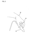
- FIG. 3 shows the surgeon's hand 32 holding a selected tool 16 holds a selector switch (not shown) in a first embodiment having.
- This selector switch is a non-contact proximity sensor this first embodiment is designed as an inductive proximity sensor.
- inductive proximity sensors are known per se in the prior art, here a description of their structure and functioning is dispensed with.
- the proximity sensor works with a detection element, which in the Regarding the inductive proximity sensor is electrically conductive and here as a metal ring 34 is present, the surgeon on the index finger of the selected tool 16 holding hand 32 carries.
- the inductive proximity sensor is in the housing of the tool 16 arranged and adjusted so that he this tool 16 releases when the surgeon holds it in his hand 32 and thus the ring 34 is in the response range of the sensor.
- ring 34 also becomes the response range of the inductive proximity sensor removed so that it locks the tool 16 assigned to it.
- FIG. 4 shows the tool 16 of FIG. 3, however, is here as a recognition element a metal plate 36 for the inductive proximity sensor instead of a ring 34 provided that on the back of the hand holding the tool 16 hand 32 of the Surgeon is glued.
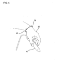
- the FIG. 5 shows a selected tool 16 with its own selector switch in FIG a second embodiment.
- the selector switch is non-contact Proximity sensor (not shown) that works with a detection element.
- the proximity sensor has one Transmitter for emitting an interrogation signal and a receiver for an identification signal on.
- the detection element 38 has a transponder (not shown) on which a receiver for the interrogation signal, a transmitter for emitting the Identification signal and a control circuit. This control circuit is like this trained that the transponder emits the identification signal only if it Interrogation signal received.
- the detection element 38 with the transponder is here attached to a bracelet 40 which the surgeon uses on his wrist the tool 16 holding hand 32 carries.
- the transmission powers of the interrogation signal transmitter and the identification signal transmitter and the reception sensitivities of the interrogation signal receiver and the identification signal receiver define the response range of this non-contact proximity sensor and are selected such that, as already shown above in FIG. 3 explains the tool 16 is released when the surgeon holds it in his hand 32, ie in close to the transponder that it is locked as soon as it is off this hand 32 places and, for example, one of the other, previously blocked tools 14 takes in hand 32.
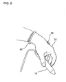
- FIG. 6 shows the tool 16 of FIG. 5, but here is the recognition element 38 attached to the transponder on a disposable glove 42.
- FIG. 7 shows a selected tool 16 that has a selector switch in one third embodiment.
- the selector switch is a push button 44 here is arranged in the grip area of the tool 16 in such a way that it is removed by the surgeon can be conveniently operated when using the tool 16.
- the push button 44 is arranged, for example, under the index finger of the hand 32.
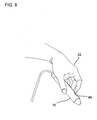
- FIG. 8 shows a selected tool 16 that has a selector switch in one fourth embodiment.
- the push button is 44 of FIG. 7 replaced by a light barrier (not shown), which also is arranged in the grip area of the tool 16.
- FIG. 8 shows that Housing of the tool 16 under the fingertip of the index finger of the hand 32 a recess 46.
- the transmitter and receiver are inside the housing the light barrier arranged in such a way that the inwardly curved wall of the Well 46 lies between them. This wall is transparent so that the light emitted by the transmitter hits the receiver through the wall can.
- This light beam is interrupted when the tip of the index finger, as in the FIG. 8 shown, rests in the recess.
Landscapes
- Health & Medical Sciences (AREA)
- Life Sciences & Earth Sciences (AREA)
- Surgery (AREA)
- General Health & Medical Sciences (AREA)
- Veterinary Medicine (AREA)
- Biomedical Technology (AREA)
- Heart & Thoracic Surgery (AREA)
- Medical Informatics (AREA)
- Molecular Biology (AREA)
- Animal Behavior & Ethology (AREA)
- Nuclear Medicine, Radiotherapy & Molecular Imaging (AREA)
- Public Health (AREA)
- Engineering & Computer Science (AREA)
- Surgical Instruments (AREA)
- Laser Surgery Devices (AREA)
- Prostheses (AREA)
- Accommodation For Nursing Or Treatment Tables (AREA)
- Push-Button Switches (AREA)
- Electrotherapy Devices (AREA)
- Materials For Medical Uses (AREA)
Abstract
Description
- FIG. 1
- ist eine perspektivische Gesamtansicht, die eine chirurgische Werkzeugstation in einer ersten Ausführungsform zeigt;
- FIG. 2
- ist eine perspektivische Gesamtansicht, die eine chirurgische Werkzeugstation in einer zweiten Ausführungsform zeigt;
- FIG. 3
- ist eine Detailansicht, die ein Werkzeug mit einem eigenen Wahlschalter in einer ersten Ausführungsform zeigt;
- FIG. 4
- ist eine Detailansicht, die das Werkzeug der FIG. 3 mit einem anderen Erkennungselement zeigt;
- FIG. 5
- ist eine Detailansicht, die ein Werkzeug mit einem eigenen Wahlschalter in einer zweiten Ausführungsform zeigt;
- FIG. 6
- ist eine Detailansicht, die das Werkzeug der FIG. 5 und eine alternative Plazierung des Transponders zeigt;
- FIG. 7
- ist eine Detailansicht, die ein Werkzeug mit einem eigenen Wahlschalter in einer dritten Ausführungsform zeigt;
- FIG. 8
- ist eine Detailansicht, die ein Werkzeug mit einem eigenen Wahlschalter in einer vierten Ausführungsform zeigt;
- FIG. 9
- ist eine perspektivische Gesamtdarstellung, die eine bekannte chirurgische Werkzeugstation zeigt.
- 10
- Operationstisch
- 12
- Werkzeugstation
- 14
- gesperrtes Werkzeug
- 16
- ausgewähltes, freigegebenes Werkzeug
- 18
- Steuereinheit
- 20
- Wellen
- 22
- Lichtleiterkabel
- 24
- Drehschalter
- 26
- Fußschalter
- 28
- Kabel
- 30
- Signalleuchte
- 32
- Hand
- 34
- Ring
- 36
- Plakette
- 38
- Erkennungselement mit Transponder
- 40
- Armband
- 42
- Einweghandschuh
- 44
- Drucktaster
- 46
- Vertiefung
Claims (10)
- Chirurgische Werkzeugstation, mit:dadurch gekennzeichnet, dasswenigstens zwei mit Hilfsenergie betriebenen Werkzeugen (14, 16);einer Schalteranordnung (24, 26; 44, 26) zum selektiven Ein- und Ausschalten der Werkzeuge (14, 16);einer Steuereinheit (18), die bei Betätigung der Schalteranordnung (24, 26; 44, 26) die Hilfsenergie an ein ausgewähltes Werkzeug (16) leitet,die Schalteranordnung wenigstens einen Wahlschalter (24, 44) zum Auswählen eines Werkzeugs (16) und einen Hauptschalter (26) zum Ein- und Ausschalten dieses ausgewählten Werkzeugs (16) aufweist.
- Werkzeugstation nach Anspruch 1, dadurch gekennzeichnet, dass jedes Werkzeug (14, 16) einen eigenen Wahlschalter aufweist, der einen berührungslosen Näherungssensor aufweist, der mit einem Erkennungselement (34, 36, 38) zusammenarbeitet.
- Werkzeugstation nach Anspruch 2, dadurch gekennzeichnet, dass der Näherungssensor einen induktiven Näherungssensor aufweist, und dass das Erkennungselement (34, 36) elektrisch leitfähig ist.
- Werkzeugstation nach Anspruch 2, dadurch gekennzeichnet, dass das Erkennungselement (38) einen Sender zur Abstrahlung eines Kennsignals und der Näherungssensor einen Empfänger für das Kennsignal aufweist.
- Werkzeugstation nach Anspruch 4, dadurch gekennzeichnet, dass der Näherungssensor einen Sender zur Abstrahlung eines Abfragesignals und das Erkennungselement (38) einen Transponder aufweist, der so ausgebildet ist, dass er das Kennsignal nur dann abstrahlt, wenn er das Abfragesignal empfängt.
- Werkzeugstation nach einem der vorhergehenden Ansprüche, dadurch gekennzeichnet, dass der Wahlschalter (24) an der Steuereinheit (18) angeordnet ist, und dass jedes Werkzeug (14, 16) eine Signalleuchte (30) aufweist, die nur dann von der Steuereinheit (18) angesteuert wird, wenn das ihr zugeordnete Werkzeug (14, 16) durch den Wahlschalter (24) ausgewählt ist.
- Werkzeugstation nach einem der vorhergehenden Ansprüche, dadurch gekennzeichnet, dass jedes Werkzeug (14, 16) einen eigenen Wahlschalter (44) aufweist, der im Griffbereich des Werkzeugs (14, 16) angeordnet ist.
- Werkzeugstation nach Anspruch 7, dadurch gekennzeichnet, dass der Wahlschalter ein Drucktaster (44) ist.
- Werkzeugstation nach Anspruch 7, dadurch gekennzeichnet, dass der Wahlschalter eine Lichtschranke ist.
- Werkzeugstation nach einem der vorhergehenden Ansprüche, dadurch gekennzeichnet, dass der Hauptschalter ein Fußschalter (26) ist.
Applications Claiming Priority (2)
| Application Number | Priority Date | Filing Date | Title |
|---|---|---|---|
| DE19945208 | 1999-09-22 | ||
| DE19945208A DE19945208A1 (de) | 1999-09-22 | 1999-09-22 | Chirurgische Werkzeugstation |
Publications (2)
| Publication Number | Publication Date |
|---|---|
| EP1116477A1 true EP1116477A1 (de) | 2001-07-18 |
| EP1116477B1 EP1116477B1 (de) | 2006-05-03 |
Family
ID=7922769
Family Applications (1)
| Application Number | Title | Priority Date | Filing Date |
|---|---|---|---|
| EP00120737A Expired - Lifetime EP1116477B1 (de) | 1999-09-22 | 2000-09-22 | Chirurgische Werkzeugstation |
Country Status (9)
| Country | Link |
|---|---|
| EP (1) | EP1116477B1 (de) |
| AT (1) | ATE324837T1 (de) |
| AU (1) | AU1990901A (de) |
| CY (1) | CY1105524T1 (de) |
| DE (3) | DE19945208A1 (de) |
| DK (1) | DK1116477T3 (de) |
| ES (1) | ES2263424T3 (de) |
| PT (1) | PT1116477E (de) |
| WO (1) | WO2001021056A2 (de) |
Cited By (1)
| Publication number | Priority date | Publication date | Assignee | Title |
|---|---|---|---|---|
| CN110636811A (zh) * | 2017-05-24 | 2019-12-31 | 柯惠Lp公司 | 用于机器人手术系统的踏板控制 |
Families Citing this family (6)
| Publication number | Priority date | Publication date | Assignee | Title |
|---|---|---|---|---|
| EP1321164A1 (de) * | 2001-12-21 | 2003-06-25 | Ultra Scientific Instruments Limited | Signalleuchte |
| DE102004037859B4 (de) * | 2004-08-04 | 2007-05-16 | Siemens Ag | Medizinisches Gerät mit Einrichtung zur Kollisionvermeidung |
| DE102007018811B4 (de) | 2007-04-20 | 2009-07-09 | Siemens Ag | Vorrichtung mit einem beweglichen Patiententisch und/oder Deckenstativ und Verfahren zum Ermöglichen des Bewegens eines beweglichen Patiententischs und /oder Deckenstativs nur durch eine berechtigte Bedienperson |
| JP6203249B2 (ja) * | 2013-03-29 | 2017-09-27 | オリンパス株式会社 | マスタスレーブシステム |
| DE102018133504A1 (de) | 2018-12-21 | 2020-06-25 | Aesculap Ag | Integrierte Leistungseinheit IPU |
| DE102019101308A1 (de) | 2019-01-18 | 2020-07-23 | Aesculap Ag | Integrierte Leistungseinheit IPU |
Citations (5)
| Publication number | Priority date | Publication date | Assignee | Title |
|---|---|---|---|---|
| US4705038A (en) * | 1985-01-23 | 1987-11-10 | Dyonics, Inc. | Surgical system for powered instruments |
| US4936842A (en) * | 1987-05-08 | 1990-06-26 | Circon Corporation | Electrosurgical probe apparatus |
| DE8621578U1 (de) * | 1986-08-11 | 1991-02-21 | Siemens AG, 1000 Berlin und 8000 München | HF-Chirurgiegerät mit Leistungssteuerung vom Chirurgie-Handgriff aus |
| EP0548031A1 (de) * | 1991-12-11 | 1993-06-23 | Alberto Boni | Tragbare Multifunktionseinheit zur mehrfachen chirurgischen Verwendung |
| US5871493A (en) * | 1995-10-31 | 1999-02-16 | Smith & Nephew Endoscopy Inc. | Surgical instrument handpiece and system |
Family Cites Families (3)
| Publication number | Priority date | Publication date | Assignee | Title |
|---|---|---|---|---|
| DE3014893A1 (de) * | 1980-04-17 | 1981-10-22 | Siemens AG, 1000 Berlin und 8000 München | Steuereinrichtung fuer ein zahnaerztliches geraet |
| DE8815990U1 (de) * | 1988-12-23 | 1989-12-28 | Diamantidis, Georg, 7014 Kornwestheim | Einrichtung zur visuellen Betrachtung der Chlorophyllfluoreszenz in der Umwelt |
| DE19501581C2 (de) * | 1995-01-20 | 1998-08-27 | Huettinger Medtech Gmbh | Bedienungseinrichtung für medizinisch-technische Systemarbeitsplätze |
-
1999
- 1999-09-22 DE DE19945208A patent/DE19945208A1/de not_active Withdrawn
-
2000
- 2000-09-22 ES ES00120737T patent/ES2263424T3/es not_active Expired - Lifetime
- 2000-09-22 AU AU19909/01A patent/AU1990901A/en not_active Withdrawn
- 2000-09-22 DE DE10082822T patent/DE10082822D2/de not_active Expired - Fee Related
- 2000-09-22 AT AT00120737T patent/ATE324837T1/de not_active IP Right Cessation
- 2000-09-22 DK DK00120737T patent/DK1116477T3/da active
- 2000-09-22 PT PT00120737T patent/PT1116477E/pt unknown
- 2000-09-22 WO PCT/DE2000/003322 patent/WO2001021056A2/de not_active Ceased
- 2000-09-22 EP EP00120737A patent/EP1116477B1/de not_active Expired - Lifetime
- 2000-09-22 DE DE50012689T patent/DE50012689D1/de not_active Expired - Fee Related
-
2006
- 2006-08-03 CY CY20061101087T patent/CY1105524T1/el unknown
Patent Citations (5)
| Publication number | Priority date | Publication date | Assignee | Title |
|---|---|---|---|---|
| US4705038A (en) * | 1985-01-23 | 1987-11-10 | Dyonics, Inc. | Surgical system for powered instruments |
| DE8621578U1 (de) * | 1986-08-11 | 1991-02-21 | Siemens AG, 1000 Berlin und 8000 München | HF-Chirurgiegerät mit Leistungssteuerung vom Chirurgie-Handgriff aus |
| US4936842A (en) * | 1987-05-08 | 1990-06-26 | Circon Corporation | Electrosurgical probe apparatus |
| EP0548031A1 (de) * | 1991-12-11 | 1993-06-23 | Alberto Boni | Tragbare Multifunktionseinheit zur mehrfachen chirurgischen Verwendung |
| US5871493A (en) * | 1995-10-31 | 1999-02-16 | Smith & Nephew Endoscopy Inc. | Surgical instrument handpiece and system |
Cited By (4)
| Publication number | Priority date | Publication date | Assignee | Title |
|---|---|---|---|---|
| CN110636811A (zh) * | 2017-05-24 | 2019-12-31 | 柯惠Lp公司 | 用于机器人手术系统的踏板控制 |
| CN110678140A (zh) * | 2017-05-24 | 2020-01-10 | 柯惠Lp公司 | 用于机器人手术系统的踏板控制 |
| EP3629974A4 (de) * | 2017-05-24 | 2021-04-21 | Covidien LP | Pedalsteuerung für robotische chirurgische systeme |
| US11369446B2 (en) | 2017-05-24 | 2022-06-28 | Covidien Lp | Pedal control for robotic surgical systems |
Also Published As
| Publication number | Publication date |
|---|---|
| EP1116477B1 (de) | 2006-05-03 |
| PT1116477E (pt) | 2006-09-29 |
| DE10082822D2 (de) | 2002-08-14 |
| DE19945208A1 (de) | 2001-04-26 |
| DK1116477T3 (da) | 2006-09-11 |
| ATE324837T1 (de) | 2006-06-15 |
| ES2263424T3 (es) | 2006-12-16 |
| AU1990901A (en) | 2001-04-24 |
| WO2001021056A2 (de) | 2001-03-29 |
| DE50012689D1 (de) | 2006-06-08 |
| CY1105524T1 (el) | 2010-07-28 |
Similar Documents
| Publication | Publication Date | Title |
|---|---|---|
| EP0722750B2 (de) | Softlaser mit integriertem Punktfinder für Akupunkturpunkte | |
| DE102011113126B4 (de) | Leistungseinheit und medizinisches Handgerät | |
| DE3689730T2 (de) | Chirurgisches System für angetriebene Werkzeuge. | |
| DE102013012397B4 (de) | OP-Robotersystem | |
| DE69206730T2 (de) | Handgriff für chirurgische Instrumente | |
| EP0521261A1 (de) | Medizinisches Instrument mit einem Schalter zum Steuern externer Geräte | |
| DE3601453C2 (de) | ||
| EP1990021B1 (de) | Medizinisches Instrument mit separater Sendereinheit zur Ansteuerung einer behandlungsunterstützenden Software, sowie Instrumentensystem | |
| DE2724324C2 (de) | Vorrichtung zum Zertrümmern von Blasensteinen | |
| EP3273900A1 (de) | Haltearm für medizinische zwecke mit abnehmbarer bedieneinrichtung, sowie bedieneinrichtung hierfür | |
| EP1116477A1 (de) | Chirurgische Werkzeugstation | |
| DE3837048A1 (de) | Lasergeraet | |
| DE60025106T2 (de) | Laserbehandlungsgerät mit Anwender-Anwesenheitskontrolle | |
| DE202006018938U1 (de) | Handmetalldetektor | |
| EP1090602A1 (de) | Zahnmedizinische Einrichtung | |
| EP1255487A1 (de) | Laserindikator | |
| EP1440756B1 (de) | Motorische Schneidevorrichtung | |
| DE29916710U1 (de) | Chirurgische Werkzeugstation | |
| EP3518801B1 (de) | System zur chirurgischen behandlung | |
| EP0617298B1 (de) | Ablagevorrichtung für ärztliche oder zahnärztliche Behandlungsinstrumente mit einer Lichtschranke | |
| WO2005001679A1 (de) | Verfahren und vorrichtung zur auswahl eines bestimmten bereichs einer anzeigefläche | |
| DE4429812C2 (de) | Handhabe für endoskopische Geräte | |
| DE102017222041B3 (de) | Medizinisches Instrument und Endoskopiesystem, das dasselbe umfasst | |
| DE60000300T2 (de) | Vorrichtung zur Phako-Emulgierung | |
| DE102020114426A1 (de) | Gerätesteuerung |
Legal Events
| Date | Code | Title | Description |
|---|---|---|---|
| PUAI | Public reference made under article 153(3) epc to a published international application that has entered the european phase |
Free format text: ORIGINAL CODE: 0009012 |
|
| AK | Designated contracting states |
Kind code of ref document: A1 Designated state(s): AT BE CH CY DE DK ES FI FR GB GR IE IT LI LU MC NL PT SE |
|
| AX | Request for extension of the european patent |
Free format text: AL;LT;LV;MK;RO;SI |
|
| 17P | Request for examination filed |
Effective date: 20020116 |
|
| AKX | Designation fees paid |
Free format text: AT BE CH CY DE DK ES FI FR GB GR IE IT LI LU MC NL PT SE |
|
| 17Q | First examination report despatched |
Effective date: 20020729 |
|
| GRAP | Despatch of communication of intention to grant a patent |
Free format text: ORIGINAL CODE: EPIDOSNIGR1 |
|
| GRAS | Grant fee paid |
Free format text: ORIGINAL CODE: EPIDOSNIGR3 |
|
| GRAA | (expected) grant |
Free format text: ORIGINAL CODE: 0009210 |
|
| AK | Designated contracting states |
Kind code of ref document: B1 Designated state(s): AT BE CH CY DE DK ES FI FR GB GR IE IT LI LU MC NL PT SE |
|
| REG | Reference to a national code |
Ref country code: GB Ref legal event code: FG4D Free format text: NOT ENGLISH |
|
| REG | Reference to a national code |
Ref country code: CH Ref legal event code: EP |
|
| REF | Corresponds to: |
Ref document number: 50012689 Country of ref document: DE Date of ref document: 20060608 Kind code of ref document: P |
|
| REG | Reference to a national code |
Ref country code: IE Ref legal event code: FG4D Free format text: LANGUAGE OF EP DOCUMENT: GERMAN |
|
| REG | Reference to a national code |
Ref country code: SE Ref legal event code: TRGR |
|
| REG | Reference to a national code |
Ref country code: DK Ref legal event code: T3 |
|
| GBT | Gb: translation of ep patent filed (gb section 77(6)(a)/1977) |
Effective date: 20060830 |
|
| PGFP | Annual fee paid to national office [announced via postgrant information from national office to epo] |
Ref country code: IE Payment date: 20060920 Year of fee payment: 7 |
|
| PGFP | Annual fee paid to national office [announced via postgrant information from national office to epo] |
Ref country code: DK Payment date: 20060921 Year of fee payment: 7 Ref country code: GB Payment date: 20060921 Year of fee payment: 7 |
|
| PGFP | Annual fee paid to national office [announced via postgrant information from national office to epo] |
Ref country code: CH Payment date: 20060922 Year of fee payment: 7 Ref country code: DE Payment date: 20060922 Year of fee payment: 7 |
|
| PGFP | Annual fee paid to national office [announced via postgrant information from national office to epo] |
Ref country code: GR Payment date: 20060925 Year of fee payment: 7 Ref country code: MC Payment date: 20060925 Year of fee payment: 7 |
|
| PGFP | Annual fee paid to national office [announced via postgrant information from national office to epo] |
Ref country code: AT Payment date: 20060926 Year of fee payment: 7 Ref country code: BE Payment date: 20060926 Year of fee payment: 7 Ref country code: ES Payment date: 20060926 Year of fee payment: 7 |
|
| PGFP | Annual fee paid to national office [announced via postgrant information from national office to epo] |
Ref country code: FI Payment date: 20060927 Year of fee payment: 7 Ref country code: NL Payment date: 20060927 Year of fee payment: 7 |
|
| REG | Reference to a national code |
Ref country code: PT Ref legal event code: SC4A Effective date: 20060803 |
|
| PGFP | Annual fee paid to national office [announced via postgrant information from national office to epo] |
Ref country code: IT Payment date: 20060930 Year of fee payment: 7 |
|
| REG | Reference to a national code |
Ref country code: GR Ref legal event code: EP Ref document number: 20060402680 Country of ref document: GR |
|
| PGFP | Annual fee paid to national office [announced via postgrant information from national office to epo] |
Ref country code: PT Payment date: 20061013 Year of fee payment: 7 |
|
| PGFP | Annual fee paid to national office [announced via postgrant information from national office to epo] |
Ref country code: CY Payment date: 20061016 Year of fee payment: 7 |
|
| PGFP | Annual fee paid to national office [announced via postgrant information from national office to epo] |
Ref country code: LU Payment date: 20061024 Year of fee payment: 7 |
|
| REG | Reference to a national code |
Ref country code: ES Ref legal event code: FG2A Ref document number: 2263424 Country of ref document: ES Kind code of ref document: T3 |
|
| ET | Fr: translation filed | ||
| PLBE | No opposition filed within time limit |
Free format text: ORIGINAL CODE: 0009261 |
|
| STAA | Information on the status of an ep patent application or granted ep patent |
Free format text: STATUS: NO OPPOSITION FILED WITHIN TIME LIMIT |
|
| 26N | No opposition filed |
Effective date: 20070206 |
|
| REG | Reference to a national code |
Ref country code: FR Ref legal event code: ST Effective date: 20070531 |
|
| REG | Reference to a national code |
Ref country code: FR Ref legal event code: RN |
|
| REG | Reference to a national code |
Ref country code: FR Ref legal event code: FC |
|
| PGFP | Annual fee paid to national office [announced via postgrant information from national office to epo] |
Ref country code: SE Payment date: 20060920 Year of fee payment: 7 |
|
| BERE | Be: lapsed |
Owner name: *ADRIAN UTE Effective date: 20070930 |
|
| REG | Reference to a national code |
Ref country code: PT Ref legal event code: MM4A Free format text: LAPSE DUE TO NON-PAYMENT OF FEES Effective date: 20080324 |
|
| PG25 | Lapsed in a contracting state [announced via postgrant information from national office to epo] |
Ref country code: MC Free format text: LAPSE BECAUSE OF NON-PAYMENT OF DUE FEES Effective date: 20070930 Ref country code: SE Free format text: LAPSE BECAUSE OF NON-PAYMENT OF DUE FEES Effective date: 20070923 Ref country code: FR Free format text: LAPSE BECAUSE OF NON-PAYMENT OF DUE FEES Effective date: 20061002 |
|
| PGFP | Annual fee paid to national office [announced via postgrant information from national office to epo] |
Ref country code: FR Payment date: 20070814 Year of fee payment: 8 |
|
| REG | Reference to a national code |
Ref country code: DK Ref legal event code: EBP |
|
| REG | Reference to a national code |
Ref country code: CH Ref legal event code: PL |
|
| EUG | Se: european patent has lapsed | ||
| GBPC | Gb: european patent ceased through non-payment of renewal fee |
Effective date: 20070922 |
|
| PG25 | Lapsed in a contracting state [announced via postgrant information from national office to epo] |
Ref country code: FI Free format text: LAPSE BECAUSE OF NON-PAYMENT OF DUE FEES Effective date: 20070922 Ref country code: PT Free format text: LAPSE BECAUSE OF NON-PAYMENT OF DUE FEES Effective date: 20080324 Ref country code: NL Free format text: LAPSE BECAUSE OF NON-PAYMENT OF DUE FEES Effective date: 20080401 |
|
| NLV4 | Nl: lapsed or anulled due to non-payment of the annual fee |
Effective date: 20080401 |
|
| PG25 | Lapsed in a contracting state [announced via postgrant information from national office to epo] |
Ref country code: AT Free format text: LAPSE BECAUSE OF NON-PAYMENT OF DUE FEES Effective date: 20070922 |
|
| PG25 | Lapsed in a contracting state [announced via postgrant information from national office to epo] |
Ref country code: DE Free format text: LAPSE BECAUSE OF NON-PAYMENT OF DUE FEES Effective date: 20080401 Ref country code: CH Free format text: LAPSE BECAUSE OF NON-PAYMENT OF DUE FEES Effective date: 20070930 Ref country code: LI Free format text: LAPSE BECAUSE OF NON-PAYMENT OF DUE FEES Effective date: 20070930 |
|
| PGRI | Patent reinstated in contracting state [announced from national office to epo] |
Ref country code: FR Effective date: 20070913 |
|
| PG25 | Lapsed in a contracting state [announced via postgrant information from national office to epo] |
Ref country code: BE Free format text: LAPSE BECAUSE OF NON-PAYMENT OF DUE FEES Effective date: 20070930 |
|
| PG25 | Lapsed in a contracting state [announced via postgrant information from national office to epo] |
Ref country code: CY Free format text: LAPSE BECAUSE OF NON-PAYMENT OF DUE FEES Effective date: 20070922 |
|
| PG25 | Lapsed in a contracting state [announced via postgrant information from national office to epo] |
Ref country code: IE Free format text: LAPSE BECAUSE OF NON-PAYMENT OF DUE FEES Effective date: 20070924 Ref country code: GR Free format text: LAPSE BECAUSE OF NON-PAYMENT OF DUE FEES Effective date: 20060804 Ref country code: DK Free format text: LAPSE BECAUSE OF NON-PAYMENT OF DUE FEES Effective date: 20071001 |
|
| PG25 | Lapsed in a contracting state [announced via postgrant information from national office to epo] |
Ref country code: GB Free format text: LAPSE BECAUSE OF NON-PAYMENT OF DUE FEES Effective date: 20070922 |
|
| REG | Reference to a national code |
Ref country code: ES Ref legal event code: FD2A Effective date: 20070924 |
|
| PG25 | Lapsed in a contracting state [announced via postgrant information from national office to epo] |
Ref country code: ES Free format text: LAPSE BECAUSE OF NON-PAYMENT OF DUE FEES Effective date: 20070924 |
|
| REG | Reference to a national code |
Ref country code: FR Ref legal event code: ST Effective date: 20090529 |
|
| PG25 | Lapsed in a contracting state [announced via postgrant information from national office to epo] |
Ref country code: LU Free format text: LAPSE BECAUSE OF NON-PAYMENT OF DUE FEES Effective date: 20070922 Ref country code: IT Free format text: LAPSE BECAUSE OF NON-PAYMENT OF DUE FEES Effective date: 20070922 |
|
| PG25 | Lapsed in a contracting state [announced via postgrant information from national office to epo] |
Ref country code: FR Free format text: LAPSE BECAUSE OF NON-PAYMENT OF DUE FEES Effective date: 20080930 |