EP1115040B1 - Antriebsvorrichtung für Uhrwerk mit grosser Gangreserve - Google Patents
Antriebsvorrichtung für Uhrwerk mit grosser Gangreserve Download PDFInfo
- Publication number
- EP1115040B1 EP1115040B1 EP00126767A EP00126767A EP1115040B1 EP 1115040 B1 EP1115040 B1 EP 1115040B1 EP 00126767 A EP00126767 A EP 00126767A EP 00126767 A EP00126767 A EP 00126767A EP 1115040 B1 EP1115040 B1 EP 1115040B1
- Authority
- EP
- European Patent Office
- Prior art keywords
- wheel
- barrel
- group
- cage
- barrels
- Prior art date
- Legal status (The legal status is an assumption and is not a legal conclusion. Google has not performed a legal analysis and makes no representation as to the accuracy of the status listed.)
- Expired - Lifetime
Links
Images


Classifications
-
- G—PHYSICS
- G04—HOROLOGY
- G04B—MECHANICALLY-DRIVEN CLOCKS OR WATCHES; MECHANICAL PARTS OF CLOCKS OR WATCHES IN GENERAL; TIME PIECES USING THE POSITION OF THE SUN, MOON OR STARS
- G04B1/00—Driving mechanisms
- G04B1/10—Driving mechanisms with mainspring
- G04B1/12—Driving mechanisms with mainspring with several mainsprings
-
- G—PHYSICS
- G04—HOROLOGY
- G04B—MECHANICALLY-DRIVEN CLOCKS OR WATCHES; MECHANICAL PARTS OF CLOCKS OR WATCHES IN GENERAL; TIME PIECES USING THE POSITION OF THE SUN, MOON OR STARS
- G04B1/00—Driving mechanisms
- G04B1/10—Driving mechanisms with mainspring
- G04B1/18—Constructions for connecting the ends of the mainsprings with the barrel or the arbor
- G04B1/185—Friction clutch between spring and spring cylinder
-
- G—PHYSICS
- G04—HOROLOGY
- G04B—MECHANICALLY-DRIVEN CLOCKS OR WATCHES; MECHANICAL PARTS OF CLOCKS OR WATCHES IN GENERAL; TIME PIECES USING THE POSITION OF THE SUN, MOON OR STARS
- G04B9/00—Supervision of the state of winding, e.g. indicating the amount of winding
- G04B9/005—Supervision of the state of winding, e.g. indicating the amount of winding by optical indication of the amount of winding
Definitions
- the present invention relates to a watch movement with a large power reserve and more particularly to a mechanism comprising a motor device comprising several barrels, a manual winding gear of this motor device and possibly a power reserve indication wheel.
- a multiple barrel motor device of the document is also known.
- FR-1195976 whose spring is composed of a plurality of spirals connected in series on one or more parallel axes. This device is however very bulky and can not be suitable for a pocket watch movement or bracelet.
- One of the aims of the present invention is to provide a motor device for a watch movement, in particular for a pocket watch or a wristwatch, which has a size compatible with a caliber of pocket watch or wristwatch and which allows the obtaining a power reserve greater than one week, preferably between 8 and 10 days.
- Another object of the present invention is to provide this motor device with an indication wheel of the power reserve.
- Another object of the invention is to allow the reassembly of the motor device beyond the value corresponding to the maximum indication of power reserve without distorting this indication.
- Yet another purpose is to provide in the motor device a provision that the user can manually raise the motor device beyond its maximum winding without damage to it.
- the present invention relates to a watch movement, in particular for a wristwatch and pocket watch, having a large power reserve comprising a motor device reassembled using a winding train and driving a finishing gear that distinguished by the features set forth in claim 1.
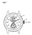
- the timepiece is a wristwatch comprising a movement housed in a box 1 provided with a winding crown 2 and whose dial 3 comprises a time display, a small second, a date display and a display of the power reserve comprising a graduation 4, bearing the numbers 0 to 8 indicating in days the power reserve, and a needle 5 cooperating with this graduation 4.
- the watch movement according to the present invention comprises a large power reserve of between eight and ten days, in all cases exceeding one week. In this way the user does not have to reassemble his watch only once a week and the engine torque is sufficiently stable to ensure a required accuracy of the chronometers.
- This power reserve watch movement comprises an engine mechanism comprising four barrels, a manual winding gear and, in the illustrated embodiment, a power reserve indication wheel.
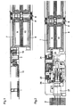
- the motor device of this watch movement comprises two groups of two superposed barrels arranged side by side.
- the first group of superposed barrels comprises two barrel cages mounted and pivoted on the same axis 6, ie a first barrel cage 7 and a second barrel cage 8.
- the first barrel cage 7 houses a first barrel spring 9 whose the inner end is integral with the core 6 'while the outer end is integral with a friction flange slidable in the first barrel cage when the friction force exceeds a predetermined value.
- the first barrel cage 7 is provided with an external toothing engaged with a barrel pawl 10 subjected to the action of a pawl spring 11, so that the first barrel cage can only rotate in one direction .
- the second barrel cage 8 encloses a second barrel spring 12 whose inner end is integral with the core 6 ', while its outer end is integral with the second barrel cage 8.
- the second barrel cage 8 has an external toothing meshing with a barrel return 13.
- the second group of two superposed barrels comprises an axis 14 on which are pivotally mounted a third barrel cage 15 and a fourth barrel cage 16.
- the third barrel cage 15 has an external toothing engaged with the barrel return 13 and encloses a third barrel spring 17 whose outer end is integral with the third barrel cage 15 and whose inner end is integral with the core 14 '.
- the fourth barrel cage 16 encloses a fourth barrel spring 18 whose inner end is integral with the core 14 ', while the outer end is integral with this fourth barrel cage 16.
- This fourth barrel cage 16 has an external toothing.
- the present movement comprises a finishing gear comprising, in the example illustrated, an intermediate wheel 19 meshing with the external toothing of the fourth cylinder cage 16 and with the pinion 20 of a medium-sized wheel whose wheel 21 is in position. taken with the pinion of a mobile of average 22 of the watch movement.
- the rest of the watch movement will not be described here, as it is conventional.
- this engine device lies in the fact that it is composed of two groups of two concentric and superimposed barrels, the second and the third barrels being engaged by means of a barrel return, the spring of the first barrel 7 being equipped with a sliding flange spring to avoid any overvoltage in the wheels, while the other three barrels 8,15,16 are equipped with springs identical to those of a manual winding watch.
- the four barrels are mounted in series so as to add up their disarming time while delivering a constant torque, the four springs having identical or substantially identical characteristics.
- the frictional torque between the flange of the first spring 9 and the first barrel cage 7 is greater than the torque delivered by the springs 9, 12, 17 and 18 in the fully raised state.
- This motor device drives the watch movement through the finishing train, it is armed with a manual winding gear.
- This manual winding gear comprises a first winding wheel whose wheel 23 is engaged with the toothing of the first cylinder cage 7 and whose pinion 24 meshes with a crown wheel 25.
- This crown wheel 25 is engaged with a winding pinion 26 when the winding stem 27 is in the depressed winding position.
- the winding of the motor device is performed by the winding crown 2 through the winding train 27,26,25,24 and 23 to the first cylinder 7 which, connected by its spring 9 to the core 6 ', weapon the second barrel 8,12 then, through the barrel return 13 up the third barrel 15,17, then through the core 14 'the fourth barrel 16,18.
- the motor device drives the finishing gear train through the cage 16 of the fourth cylinder via the intermediate wheel 19.
- the winding train comprises a first winding wheel 23.24 multiplier allowing a faster winding of the four barrels.
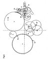
- the motor device is further equipped with a power reserve indication wheel shown in section, more particularly in the figure 3 .
- This power reserve indicating wheel actuating the hand 5 of the display of the power reserve display 4.5 comprises a first power reserve indication return 30 in engagement with the toothing of the first barrel cage 7. and meshing with a second power reserve indication return 31 angularly secured to an axis 32.
- This pin 32 carries a pinion 33 and serves as a pivot for a differential wheel 34 meshing with the teeth of the fourth cylinder cage 16.
- This axis also serves as a pivot for a differential wheel having a pinion 35 and a wheel 36.
- a satellite wheel is pivoted loosely on an axis 37 integral with the differential wheel 34.
- This satellite mobile comprises a pinion 38 engaged with the wheel 36 of the differential wheel and a wheel 39 in engagement with the pinion 33 of the shaft 32.
- the pinion 35 of the differential gear is engaged with the wheel 40 of a first power reserve indication wheel, whose pinion 41 meshes with the wheel. 42 of a second mobile power reserve indication, the pinion 43 is engaged with the wheel 44 of an indicator mobile 46, the axis 45 carries the needle 5 of the display of the reserve of walk.
- the wheel 44 of the indicator mobile is mounted frictionally on the indicator mobile 45,46.
- the indicator mobile 45,46 carries a pin 47 cooperating with a fixed stop 48.
- the needle 5 of the power reserve display is opposite the largest digit of the scale 4 indicating that the power reserve is at its maximum.
- This maximum indication of the display of the power reserve corresponds to the complete reassembly of the motor device.
- the needle 5 reaches the end of the stroke and the mobile indicator 46 is held in this angular position by the pin 47 and the stop 48.
- the wheel 44 moves angularly under the action of the power reserve indication wheel relative to the indicator mobile, thanks to its friction coupling, that is until the engine device is fully reassembled and the flange of the first spring 9 of the first barrel slides in the first barrel cage 7.
- the needle 5 indicates a maximum power reserve, corresponding to the complete reassembly of the motor device. This has the corollary that, when the needle 5 displays 0 on the power reserve graduation 4, the motor device is not yet completely disarmed, but it still ensures sufficient torque for the smooth running of the watch movement . Thus, the user is certain to reassemble his watch well before it stops.
- the cage of the first barrel 7 drives the first reserve power reserve 30, the second reserve power reserve 31 and therefore the pinion 33, the satellite mobile 38,39, and the pinion 35 which drives the mobile indicator 46 carrying the needle 5 through the two power reserve indication mobiles 40,41 and 42,43, until this needle 5 indicates the maximum of the power reserve, the mobile indicator being then immobilized by the pin 47 coming into contact with the stop 48.
- the user can continue to reassemble the motor device, the wheel 44 being able to slip frictionally on the indicator wheel 46, until the four barrel springs are completely armed and that the flange of the first mainspring 9 slides on the first barrel cage 7.
- the indicator wheel 46 and its wheel 44 are driven by the fourth cylinder cage 16, the differential wheel 34, the satellite 38,39, the differential wheel 35,36 and the power-reserve indicating mobiles. 40.41 and 42.43.
- the needle 5 therefore arrives opposite the zero of the graduation 4 before total disarming of the motor device.
- the motor device could comprise two groups of three concentric barrels, the third of which would lead to the fourth using the barrel return 13.
- the number of barrels of each group depends on the height available in the movement. The larger the number of serially mounted drums, the greater the total power reserve of the motor.
- the number of power reserve indication returns 40,41; 42,43 could be different in other constructions.
- the essence of the power reserve indication wheel is that it comprises a drive from the first cylinder of the first group and a second drive from the last cylinder of the second group driving an indicator mobile via a differential wheel and a satellite in proportion to the differential speed between the first cylinder and the last cylinder of the engine. It is, moreover, essential that the indicator wheel 46 and its wheel 44 are connected by a friction clutch and that the first mainspring is connected to the first barrel cage by a friction flange as is, for example, the case in the barrels equipping movements with automatic winding.
Landscapes
- Physics & Mathematics (AREA)
- General Physics & Mathematics (AREA)
- Measurement Of Unknown Time Intervals (AREA)
- Gear Transmission (AREA)
- Electromechanical Clocks (AREA)
- Electric Clocks (AREA)
Claims (11)
- Antriebsvorrichtung für Uhrwerk mit grosser Gangreserve aus zwei Gruppen von mindestens zwei konzentrischen Federhäusern mit einer gemeinsamen Welle, wobei das erste Federhaus der ersten Gruppe eine Feder (9) umfasst, deren äusseres Ende fest mit einer Reibungs-Schleppfeder im Gehäuse dieses ersten Federhauses (13) verbunden ist, und wobei die Federn (9, 12, 17, 18) der Federhäuser jeder Gruppe von Federhäusern mit ihren inneren Enden an einer gemeinsamen Welle (6, 14) dieser Gruppe befestigt sind; dadurch gekennzeichnet, dass das Gehäuse (8) des letzten Federhauses der ersten Gruppe das Gehäuse (15) des ersten Federhauses der zweiten Gruppe über ein Verbindungsrad des Federhauses (13) antreibt; dadurch, dass die äusseren Enden der Federn aller Federhäuser ausser dem ersten der ersten Gruppe fest mit dem entsprechenden Federhausgehäuse (7, 8, 15, 16) verbunden sind; dadurch, dass das Gehäuse (16) des letzten Federhauses der zweiten Gruppe ein Finissage-Räderwerk (19, 20, 21, 22) eines Uhrwerks antreibt, während das Gehäuse (7) des ersten Federhauses der ersten Gruppe einen Sperrkegel (10) antreibt, der der Wirkung einer Feder (11) unterworfen ist, die seine Drehung nur in einer Richtung zulässt; und dadurch, dass sich dieses Gehäuse (7) des ersten Federhauses der ersten Gruppe im Eingriff mit einem Aufzug-Drehteil (23) befindet, das durch ein Aufzug-Räderwerk (24, 25, 26, 27) angetrieben wird, das durch die Aufzugkrone (2) des Uhrwerks betätigt wird.
- Vorrichtung nach Anspruch 1, dadurch gekennzeichnet, dass jede Federhausgruppe die gleiche Anzahl von Federhäusern umfasst.
- Vorrichtung nach Anspruch 1 oder Anspruch 2, dadurch gekennzeichnet, dass jede Federhausgruppe zwei Federhäuser umfasst.
- Vorrichtung nach einem der vorangehenden Ansprüche, dadurch gekennzeichnet, dass das Aufzugrad (23) ein Multiplikatorrad ist.
- Vorrichtung nach einem der vorangehenden Ansprüche, dadurch gekennzeichnet, dass sie noch ein Räderwerk (30, 31, 33, 34, 38, 39) zur Anzeige der Gangreserve mit einem Anzeige-Drehteil (45, 46) umfasst, dessen Welle einen Zeiger (5) trägt, der mit einer Teilung (4) eines Zifferblattes (3) des Uhrwerks zusammenwirkt, wobei dieses Anzeige-Drehteil (45, 46) ein Rad (44) umfasst, das über eine Reibungskupplung auf das Drehteil (45, 46) montiert ist.
- Vorrichtung nach Anspruch 5, dadurch gekennzeichnet, dass das reibend auf das Anzeige-Drehteil (45, 46) montierte Rad (44) über ein Differenzial (33, 34, 35, 36, 38, 39) kinematisch gleichzeitig mit dem Gehäuse (7) des ersten Federhauses der ersten Gruppe und dem Gehäuse (16) des letzten Federhauses der zweiten Gruppe verbunden ist.
- Vorrichtung nach Anspruch 6, dadurch gekennzeichnet, dass das Anzeige-Drehteil (45, 46) einen Stift (47) umfasst, der mit einem Anschlag (48) zusammenwirkt, der die Winkellage dieses Drehteils (45, 46) definiert, bei der der Zeiger (5) auf der Teilung (4) die maximale Gangreserve anzeigt.
- Vorrichtung nach Anspruch 7, dadurch gekennzeichnet, dass die Stellung des Zeigers (5), die die maximale Gangreserve anzeigt, beim Aufzug der Antriebsvorrichtung erreicht wird, wenn die Federhäuser voll gespannt sind, was die Richtigkeit des Spannungszustandes der Federhausfedern (9, 12, 17, 18) gewährleistet.
- Vorrichtung nach Anspruch 8, dadurch gekennzeichnet, dass das Differenzial (33, 34, 35, 36, 38, 39) eine Welle (32) aufweist, die mit einem Ritzel (33) versehen und fest mit einem Verbindungsrad (31) der Gangreserveanzeige verbunden ist, das kinematisch mit dem Gehäuse (7) des ersten Federhauses der ersten Gruppe verbunden ist; dadurch, dass diese Welle als Drehzapfen eines Rades (34) des Differenzials dient, das kinematisch mit dem Gehäuse (16) des letzten Federhauses der zweiten Gruppe verbunden ist; dadurch, dass diese Achse (32) auch als Drehzapfen eines Differenzial-Drehteils dient, das ein Ritzel (33) aufweist, das kinematisch mit dem Rad des Anzeige-Drehteils (45, 46) und einem Rad verbunden ist, das über ein Planetenrad, das sich auf einer vom Differenzialrad (34) getragenen Welle dreht, mit dem Ritzel der Differenzialwelle verbunden ist.
- Vorrichtung nach Anspruch 9, dadurch gekennzeichnet, dass das Verbindungsrad (31) der Gangreserveanzeige über ein Verbindungsrad (30) mit dem Gehäuse (7) des ersten Federhauses der ersten Gruppe verbunden ist und dass das Ritzel des Differenzialdrehteils über zwei Drehteile der Gangreserveanzeige mit dem Rad des Anzeigedrehteils verbunden ist.
- Vorrichtung nach Anspruch 9 oder Anspruch 10, dadurch gekennzeichnet, dass sich das Differenzialrad (34) direkt mit dem letzten Gehäuse (16) des letzten Federhauses der zweiten Gruppe im Eingriff befindet.
Applications Claiming Priority (2)
| Application Number | Priority Date | Filing Date | Title |
|---|---|---|---|
| CH222000 | 2000-01-06 | ||
| CH222000 | 2000-01-06 |
Publications (2)
| Publication Number | Publication Date |
|---|---|
| EP1115040A1 EP1115040A1 (de) | 2001-07-11 |
| EP1115040B1 true EP1115040B1 (de) | 2008-03-26 |
Family
ID=4228648
Family Applications (1)
| Application Number | Title | Priority Date | Filing Date |
|---|---|---|---|
| EP00126767A Expired - Lifetime EP1115040B1 (de) | 2000-01-06 | 2000-12-06 | Antriebsvorrichtung für Uhrwerk mit grosser Gangreserve |
Country Status (4)
| Country | Link |
|---|---|
| EP (1) | EP1115040B1 (de) |
| JP (1) | JP4486710B2 (de) |
| AT (1) | ATE390651T1 (de) |
| DE (1) | DE60038433T2 (de) |
Families Citing this family (17)
| Publication number | Priority date | Publication date | Assignee | Title |
|---|---|---|---|---|
| EP1333345B1 (de) | 2002-02-01 | 2008-03-26 | TAG Heuer SA | Vorrichtung mit Uhrwerk und Chronographenmodul |
| CH705048B1 (fr) | 2002-07-09 | 2012-12-14 | Lvmh Swiss Mft Sa | Dispositif d'entraînement par courroies lisses ou crantées d'un mouvement de montre mécanique. |
| EP1498789A1 (de) * | 2003-07-14 | 2005-01-19 | Eterna SA | Vorrichtung zur Anzeige der Gangreserve einer mechanischen Uhr |
| DE602004016282D1 (de) | 2004-04-01 | 2008-10-16 | Richemont Int Sa | Uhrwerk mit mehreren Federhäusern |
| US8550701B2 (en) * | 2007-11-09 | 2013-10-08 | Eterna Ag Uhrenfabrik | Mechanical watch having constant spring force |
| EP2060957A1 (de) * | 2007-11-16 | 2009-05-20 | ETA SA Manufacture Horlogère Suisse | Motorelement mit federn für uhrwerk |
| CN101551635B (zh) * | 2008-03-31 | 2012-05-23 | 天津海鸥表业集团有限公司 | 一种手表同轴双层条盒联动机构 |
| CH699988A2 (fr) * | 2008-11-28 | 2010-05-31 | Patek Philippe Sa Geneve | Organe moteur pour mouvement horloger. |
| CH701968B1 (fr) * | 2009-10-12 | 2015-02-27 | Complitime Sa | Source d'énergie pour sonnerie et pièce d'horlogerie munie d'une telle source d'énergie. |
| CH702856A2 (fr) * | 2010-03-22 | 2011-09-30 | Patek Philippe Sa Geneve | Mouvement de montre. |
| CH706214B1 (fr) * | 2012-03-09 | 2016-09-30 | Sowind SA | Barillet de pièce d'horlogerie. |
| CN103235498B (zh) * | 2013-05-02 | 2016-01-06 | 王冠龙 | 一种机械表 |
| EP2977828B1 (de) * | 2014-07-21 | 2017-08-30 | ETA SA Manufacture Horlogère Suisse | Anzeige der Gangreserve einer Uhr |
| DE102016122936B4 (de) * | 2016-11-28 | 2018-11-08 | Lange Uhren Gmbh | Federhaus für eine Uhr |
| JP7135914B2 (ja) | 2019-02-12 | 2022-09-13 | セイコーエプソン株式会社 | 時計 |
| CN110161828A (zh) * | 2019-06-28 | 2019-08-23 | 辽宁孔雀表业有限公司 | 一种机械手表串联四条盒结构 |
| CN118276425B (zh) * | 2024-04-15 | 2024-10-22 | 深圳市贝伦斯智能穿戴科技有限公司 | 一种圆轴计时机构 |
Family Cites Families (4)
| Publication number | Priority date | Publication date | Assignee | Title |
|---|---|---|---|---|
| CH174430A (fr) * | 1934-04-04 | 1935-01-15 | Adolphe Thum Raymond | Moteur à ressort. |
| CH319290A (fr) * | 1954-07-13 | 1957-02-15 | Baumgartner Freres Sa | Mouvement de montre comprenant deux barrillets-moteurs |
| FR1195976A (fr) | 1957-06-25 | 1959-11-20 | M Le Directeur Du Service Des | Installation de ressorts en spirale |
| CH538715A (de) | 1967-04-15 | 1972-11-30 | Bueren Watch Company S A | Mouvement de montre à ressorts moteurs |
-
2000
- 2000-12-06 AT AT00126767T patent/ATE390651T1/de not_active IP Right Cessation
- 2000-12-06 EP EP00126767A patent/EP1115040B1/de not_active Expired - Lifetime
- 2000-12-06 DE DE60038433T patent/DE60038433T2/de not_active Expired - Lifetime
-
2001
- 2001-01-05 JP JP2001000421A patent/JP4486710B2/ja not_active Expired - Fee Related
Also Published As
| Publication number | Publication date |
|---|---|
| ATE390651T1 (de) | 2008-04-15 |
| JP2001221867A (ja) | 2001-08-17 |
| EP1115040A1 (de) | 2001-07-11 |
| DE60038433D1 (de) | 2008-05-08 |
| JP4486710B2 (ja) | 2010-06-23 |
| DE60038433T2 (de) | 2009-04-09 |
Similar Documents
| Publication | Publication Date | Title |
|---|---|---|
| EP1115040B1 (de) | Antriebsvorrichtung für Uhrwerk mit grosser Gangreserve | |
| EP2214065B1 (de) | Uhrwerk, das mit einem Vibrationswecker ausgestattet ist | |
| EP1546818B1 (de) | Mechanische vorrichtung zur anzeige von stunden und minuten | |
| EP0608535B1 (de) | Uhrwerk mit zwei entgegengesetzten Analoganzeigen | |
| EP1470452A2 (de) | Vorrichtung mit uhrwerk und chronographenmodul | |
| EP3070536B1 (de) | Uhrwerk, das eine antriebsvorrichtung einer analogen anzeige umfasst | |
| EP1772783B1 (de) | Uhrwerk mit konstantkraftvorrichtung | |
| EP3152626B1 (de) | Electronic uhrwerk mit einem analog anzeige für mehrere informationen | |
| EP3193216B1 (de) | Uhrwerksmechanismus mit tourbillon | |
| EP0392980B1 (de) | Automatische Anlage für das Aufziehen einer Uhr | |
| EP2080067A2 (de) | Zeiger für eine uhr, uhrwerk zum antrieb des zeigers und entsprechende uhr | |
| EP3705949A1 (de) | Drehmomentbegrenzungsmechanismus eines uhrwerks | |
| EP2352068B1 (de) | Anzeigemechanismus der Gangreserve | |
| CH716841A1 (fr) | Mouvement d'horlogerie à chronographe. | |
| EP3764171B1 (de) | Anzeigemechanismus eines uhranzeigewerts | |
| EP2226687A1 (de) | Auskupplungsvorrichtung für Uhrwerksmechanismus und diese Vorrichtung umfassendes Uhrwerk | |
| EP3501842B1 (de) | Anzeigevorrichtung mit rollen | |
| CH377738A (fr) | Instrument de mesure portatif | |
| EP2137578B1 (de) | Antriebsglied mit helixförmiger feder | |
| EP3168693A1 (de) | Uhrwerk | |
| EP3825786B1 (de) | Anzeigemechanismus einer uhr | |
| EP3769159B1 (de) | Zeitmessendes übertragungssystem | |
| EP4092491A1 (de) | Uhrwerk mit kupplung | |
| EP4498172A1 (de) | Uhrwerk, das einen mechanismus zur indexierung der relativen position zwischen anzeigevorrichtungen der zweiten strom und stromminuten umfasst | |
| EP3316045A1 (de) | Uhrwerk mit mehreren federhäusern |
Legal Events
| Date | Code | Title | Description |
|---|---|---|---|
| PUAI | Public reference made under article 153(3) epc to a published international application that has entered the european phase |
Free format text: ORIGINAL CODE: 0009012 |
|
| AK | Designated contracting states |
Kind code of ref document: A1 Designated state(s): AT BE CH CY DE DK ES FI FR GB GR IE IT LI LU MC NL PT SE TR |
|
| AX | Request for extension of the european patent |
Free format text: AL;LT;LV;MK;RO;SI |
|
| 17P | Request for examination filed |
Effective date: 20010907 |
|
| AKX | Designation fees paid |
Free format text: AT BE CH CY DE DK ES FI FR GB GR IE IT LI LU MC NL PT SE TR |
|
| GRAP | Despatch of communication of intention to grant a patent |
Free format text: ORIGINAL CODE: EPIDOSNIGR1 |
|
| GRAS | Grant fee paid |
Free format text: ORIGINAL CODE: EPIDOSNIGR3 |
|
| GRAA | (expected) grant |
Free format text: ORIGINAL CODE: 0009210 |
|
| AK | Designated contracting states |
Kind code of ref document: B1 Designated state(s): AT BE CH CY DE DK ES FI FR GB GR IE IT LI LU MC NL PT SE TR |
|
| REG | Reference to a national code |
Ref country code: GB Ref legal event code: FG4D Free format text: NOT ENGLISH |
|
| REG | Reference to a national code |
Ref country code: CH Ref legal event code: EP Ref country code: IE Ref legal event code: FG4D Free format text: LANGUAGE OF EP DOCUMENT: FRENCH |
|
| REF | Corresponds to: |
Ref document number: 60038433 Country of ref document: DE Date of ref document: 20080508 Kind code of ref document: P |
|
| PG25 | Lapsed in a contracting state [announced via postgrant information from national office to epo] |
Ref country code: FI Free format text: LAPSE BECAUSE OF FAILURE TO SUBMIT A TRANSLATION OF THE DESCRIPTION OR TO PAY THE FEE WITHIN THE PRESCRIBED TIME-LIMIT Effective date: 20080326 |
|
| REG | Reference to a national code |
Ref country code: CH Ref legal event code: NV Representative=s name: MICHELI & CIE SA |
|
| PG25 | Lapsed in a contracting state [announced via postgrant information from national office to epo] |
Ref country code: AT Free format text: LAPSE BECAUSE OF FAILURE TO SUBMIT A TRANSLATION OF THE DESCRIPTION OR TO PAY THE FEE WITHIN THE PRESCRIBED TIME-LIMIT Effective date: 20080326 |
|
| NLV1 | Nl: lapsed or annulled due to failure to fulfill the requirements of art. 29p and 29m of the patents act | ||
| REG | Reference to a national code |
Ref country code: IE Ref legal event code: FD4D |
|
| PG25 | Lapsed in a contracting state [announced via postgrant information from national office to epo] |
Ref country code: ES Free format text: LAPSE BECAUSE OF FAILURE TO SUBMIT A TRANSLATION OF THE DESCRIPTION OR TO PAY THE FEE WITHIN THE PRESCRIBED TIME-LIMIT Effective date: 20080707 Ref country code: PT Free format text: LAPSE BECAUSE OF FAILURE TO SUBMIT A TRANSLATION OF THE DESCRIPTION OR TO PAY THE FEE WITHIN THE PRESCRIBED TIME-LIMIT Effective date: 20080901 Ref country code: SE Free format text: LAPSE BECAUSE OF FAILURE TO SUBMIT A TRANSLATION OF THE DESCRIPTION OR TO PAY THE FEE WITHIN THE PRESCRIBED TIME-LIMIT Effective date: 20080626 |
|
| PG25 | Lapsed in a contracting state [announced via postgrant information from national office to epo] |
Ref country code: NL Free format text: LAPSE BECAUSE OF FAILURE TO SUBMIT A TRANSLATION OF THE DESCRIPTION OR TO PAY THE FEE WITHIN THE PRESCRIBED TIME-LIMIT Effective date: 20080326 |
|
| PG25 | Lapsed in a contracting state [announced via postgrant information from national office to epo] |
Ref country code: IE Free format text: LAPSE BECAUSE OF FAILURE TO SUBMIT A TRANSLATION OF THE DESCRIPTION OR TO PAY THE FEE WITHIN THE PRESCRIBED TIME-LIMIT Effective date: 20080326 Ref country code: DK Free format text: LAPSE BECAUSE OF FAILURE TO SUBMIT A TRANSLATION OF THE DESCRIPTION OR TO PAY THE FEE WITHIN THE PRESCRIBED TIME-LIMIT Effective date: 20080326 |
|
| PLBE | No opposition filed within time limit |
Free format text: ORIGINAL CODE: 0009261 |
|
| STAA | Information on the status of an ep patent application or granted ep patent |
Free format text: STATUS: NO OPPOSITION FILED WITHIN TIME LIMIT |
|
| 26N | No opposition filed |
Effective date: 20081230 |
|
| BERE | Be: lapsed |
Owner name: CHOPARD MANUFACTURE SA Effective date: 20081231 |
|
| PG25 | Lapsed in a contracting state [announced via postgrant information from national office to epo] |
Ref country code: MC Free format text: LAPSE BECAUSE OF NON-PAYMENT OF DUE FEES Effective date: 20081231 |
|
| GBPC | Gb: european patent ceased through non-payment of renewal fee |
Effective date: 20081206 |
|
| PG25 | Lapsed in a contracting state [announced via postgrant information from national office to epo] |
Ref country code: IT Free format text: LAPSE BECAUSE OF FAILURE TO SUBMIT A TRANSLATION OF THE DESCRIPTION OR TO PAY THE FEE WITHIN THE PRESCRIBED TIME-LIMIT Effective date: 20080326 |
|
| PG25 | Lapsed in a contracting state [announced via postgrant information from national office to epo] |
Ref country code: CY Free format text: LAPSE BECAUSE OF FAILURE TO SUBMIT A TRANSLATION OF THE DESCRIPTION OR TO PAY THE FEE WITHIN THE PRESCRIBED TIME-LIMIT Effective date: 20080326 Ref country code: BE Free format text: LAPSE BECAUSE OF NON-PAYMENT OF DUE FEES Effective date: 20081231 |
|
| PG25 | Lapsed in a contracting state [announced via postgrant information from national office to epo] |
Ref country code: GB Free format text: LAPSE BECAUSE OF NON-PAYMENT OF DUE FEES Effective date: 20081206 |
|
| PG25 | Lapsed in a contracting state [announced via postgrant information from national office to epo] |
Ref country code: LU Free format text: LAPSE BECAUSE OF NON-PAYMENT OF DUE FEES Effective date: 20081206 |
|
| PG25 | Lapsed in a contracting state [announced via postgrant information from national office to epo] |
Ref country code: TR Free format text: LAPSE BECAUSE OF FAILURE TO SUBMIT A TRANSLATION OF THE DESCRIPTION OR TO PAY THE FEE WITHIN THE PRESCRIBED TIME-LIMIT Effective date: 20080326 |
|
| PG25 | Lapsed in a contracting state [announced via postgrant information from national office to epo] |
Ref country code: GR Free format text: LAPSE BECAUSE OF FAILURE TO SUBMIT A TRANSLATION OF THE DESCRIPTION OR TO PAY THE FEE WITHIN THE PRESCRIBED TIME-LIMIT Effective date: 20080627 |
|
| REG | Reference to a national code |
Ref country code: FR Ref legal event code: PLFP Year of fee payment: 16 |
|
| REG | Reference to a national code |
Ref country code: FR Ref legal event code: PLFP Year of fee payment: 17 |
|
| REG | Reference to a national code |
Ref country code: FR Ref legal event code: PLFP Year of fee payment: 18 |
|
| PGFP | Annual fee paid to national office [announced via postgrant information from national office to epo] |
Ref country code: GB Payment date: 20181126 Year of fee payment: 17 |
|
| PGFP | Annual fee paid to national office [announced via postgrant information from national office to epo] |
Ref country code: DE Payment date: 20191210 Year of fee payment: 20 |
|
| PGFP | Annual fee paid to national office [announced via postgrant information from national office to epo] |
Ref country code: CH Payment date: 20191220 Year of fee payment: 20 |
|
| PG25 | Lapsed in a contracting state [announced via postgrant information from national office to epo] |
Ref country code: FR Free format text: LAPSE BECAUSE OF NON-PAYMENT OF DUE FEES Effective date: 20191231 |
|
| REG | Reference to a national code |
Ref country code: DE Ref legal event code: R071 Ref document number: 60038433 Country of ref document: DE |
|
| REG | Reference to a national code |
Ref country code: CH Ref legal event code: PL |