EP1114931A2 - Bewegliche Montageaufhängung für einen Kompressor - Google Patents
Bewegliche Montageaufhängung für einen Kompressor Download PDFInfo
- Publication number
- EP1114931A2 EP1114931A2 EP00311724A EP00311724A EP1114931A2 EP 1114931 A2 EP1114931 A2 EP 1114931A2 EP 00311724 A EP00311724 A EP 00311724A EP 00311724 A EP00311724 A EP 00311724A EP 1114931 A2 EP1114931 A2 EP 1114931A2
- Authority
- EP
- European Patent Office
- Prior art keywords
- compressor housing
- mounting lug
- main body
- mounting
- longitudinal axis
- Prior art date
- Legal status (The legal status is an assumption and is not a legal conclusion. Google has not performed a legal analysis and makes no representation as to the accuracy of the status listed.)
- Withdrawn
Links
- 238000004378 air conditioning Methods 0.000 description 2
- 238000005266 casting Methods 0.000 description 2
- 230000000295 complement effect Effects 0.000 description 2
- 238000004512 die casting Methods 0.000 description 2
- 125000006850 spacer group Chemical group 0.000 description 2
- 238000004519 manufacturing process Methods 0.000 description 1
- 230000004048 modification Effects 0.000 description 1
- 238000012986 modification Methods 0.000 description 1
Images


Classifications
-
- F—MECHANICAL ENGINEERING; LIGHTING; HEATING; WEAPONS; BLASTING
- F04—POSITIVE - DISPLACEMENT MACHINES FOR LIQUIDS; PUMPS FOR LIQUIDS OR ELASTIC FLUIDS
- F04B—POSITIVE-DISPLACEMENT MACHINES FOR LIQUIDS; PUMPS
- F04B27/00—Multi-cylinder pumps specially adapted for elastic fluids and characterised by number or arrangement of cylinders
- F04B27/08—Multi-cylinder pumps specially adapted for elastic fluids and characterised by number or arrangement of cylinders having cylinders coaxial with, or parallel or inclined to, main shaft axis
-
- F—MECHANICAL ENGINEERING; LIGHTING; HEATING; WEAPONS; BLASTING
- F04—POSITIVE - DISPLACEMENT MACHINES FOR LIQUIDS; PUMPS FOR LIQUIDS OR ELASTIC FLUIDS
- F04B—POSITIVE-DISPLACEMENT MACHINES FOR LIQUIDS; PUMPS
- F04B39/00—Component parts, details, or accessories, of pumps or pumping systems specially adapted for elastic fluids, not otherwise provided for in, or of interest apart from, groups F04B25/00 - F04B37/00
- F04B39/14—Provisions for readily assembling or disassembling
-
- F—MECHANICAL ENGINEERING; LIGHTING; HEATING; WEAPONS; BLASTING
- F04—POSITIVE - DISPLACEMENT MACHINES FOR LIQUIDS; PUMPS FOR LIQUIDS OR ELASTIC FLUIDS
- F04B—POSITIVE-DISPLACEMENT MACHINES FOR LIQUIDS; PUMPS
- F04B27/00—Multi-cylinder pumps specially adapted for elastic fluids and characterised by number or arrangement of cylinders
- F04B27/08—Multi-cylinder pumps specially adapted for elastic fluids and characterised by number or arrangement of cylinders having cylinders coaxial with, or parallel or inclined to, main shaft axis
- F04B27/10—Multi-cylinder pumps specially adapted for elastic fluids and characterised by number or arrangement of cylinders having cylinders coaxial with, or parallel or inclined to, main shaft axis having stationary cylinders
- F04B27/1036—Component parts, details, e.g. sealings, lubrication
- F04B27/1081—Casings, housings
-
- F—MECHANICAL ENGINEERING; LIGHTING; HEATING; WEAPONS; BLASTING
- F04—POSITIVE - DISPLACEMENT MACHINES FOR LIQUIDS; PUMPS FOR LIQUIDS OR ELASTIC FLUIDS
- F04B—POSITIVE-DISPLACEMENT MACHINES FOR LIQUIDS; PUMPS
- F04B39/00—Component parts, details, or accessories, of pumps or pumping systems specially adapted for elastic fluids, not otherwise provided for in, or of interest apart from, groups F04B25/00 - F04B37/00
- F04B39/12—Casings; Cylinders; Cylinder heads; Fluid connections
- F04B39/121—Casings
Definitions
- the present invention relates to a mounting lug, and more particularly to a movable mounting lug for a variable capacity swash plate type compressor adapted for use in an air conditioning system for a vehicle.
- Variable capacity swash plate type compressors are typically used in air conditioning systems for vehicles.
- the compressors are typically mounted within a vehicle engine compartment to an engine or mounting bracket by appropriate mounting lugs.
- the location of the mounting lugs on the compressor must be orientable with the mounting brackets on the vehicle and therefore dictated by the make and model of the vehicle.
- An object of the invention is to produce a movable mounting lug which may be economically produced.
- Another object of the invention is to produce a movable mounting lug wherein the mounting lug can be disposed in a variety of axial positions on the outer surface of a variable capacity swash plate type compressor.
- Another object of the invention is to produce a movable mounting lug wherein a single variable capacity swash plate type compressor may be mounted in a variety of vehicles.
- Still another object of the present invention is to produce a movable mounting lug that facilitates mounting a swash plate type compressor on vehicle models having different mounting configurations and eliminates the requirement of producing separate die casting tools for each vehicle model.
- a mounting lug comprising a main body having a centrally disposed aperture for receiving a mounting bolt, the main body extending from an outer surface of a compressor housing, wherein the main body is variably positionable on the outer surface of the compressor housing.
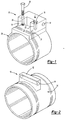
- a mounting lug according to this invention is indicated generally at 10 in Figure 1.
- the mounting lug 10 includes a main body 12.
- the main body 12 has a centrally disposed aperture 14 extending therethrough.
- Two shoulder portions 16, 18 extend outwardly from the main body 12.
- the shoulder portions 16, 18 are spaced apart from one another and extend in a generally parallel relationship to each another.
- Elongated holes 20, 22 are formed in the shoulder portions 16, 18, respectively.
- Each of the main body 12 and shoulder portions 16, 18 has a substantially planar lower surface. The lower surfaces of the main body 12 and shoulder portions 16, 18 are aligned in the same plane.
- the main body 12 and shoulder portions 16, 18 are formed as an integral member.
- the mounting lug 10 is disposed on a protruding surface 24 formed on a compressor housing 26.
- the protruding surface 24 is planar or flat.
- the compressor housing 26 is a generally cylindrical, hollow member that encloses well-known components of a compressor.
- the compressor housing 26 may be provided with one or more mounting lugs 10. The number of mounting lugs 10 which may be required depend upon the number and position of mounting brackets (not shown) that are provided on a vehicle in which the compressor housing 26 is to be mounted.
- the mounting lugs 10 can be provided at any location on the compressor housing 26.
- the location of the mounting lugs 10 is selected to correspond to the location of mounting brackets on the vehicle in which the compressor housing 26 is to be mounted.
- a protruding surface 24 is provided on an outer surface of the compressor housing 26.
- a longitudinal axis of the aperture 14 is formed to extend substantially perpendicular to a longitudinal axis of the compressor housing 26 and substantially tangent to the outer surface of the compressor housing 26.
- the mounting lug 10 can be fixedly attached at any position along the flat surface 24 of the compressor housing 26.
- the precise position of the mounting lug 10 corresponds to the mounting requirements for a vehicle, such as the position of a mounting bracket (not shown).
- the protruding surface 24 of the compressor housing 26 is drilled and tapped.
- Bolts 28, 30 are inserted through the respective holes 20, 22 of the respective shoulder portions 16, 18 and tightened in the locations drilled and tapped in the protruding surface 24 of the compressor housing 26.
- the mounting lug 10 is aligned with holes in the mounting bracket in the vehicle, and a bolt (not shown) is typically inserted through the aperture 14 of the main body 12 to secure the mounting lug 10 to the mounting bracket.
- a second embodiment of a mounting lug incorporating the features of this invention is indicated generally at 50 in Figure 2.
- the mounting lug 50 includes a main body 52 that is integrally molded onto an outer surface of a compressor housing 56.
- a lower surface of the main body 52 is complementary to the outer surface of the compressor housing 56
- the main body 52 includes a longitudinal aperture 54 that preferably extends therethrough.
- a longitudinal axis of the aperture 54 is substantially perpendicular to a longitudinal axis of the compressor housing 56 and substantially tangent to the outer surface of the compressor housing 56.
- the compressor housing 56 can have one or more mounting lugs 50 disposed thereon, depending upon the number of mounting brackets disposed on the vehicle to which the compressor housing 56 is to be mounted.
- the mounting lugs 50 may be placed at any location on the compressor housing 56, depending upon the location of the mounting brackets on the vehicle to which the compressor housing 56 is to be mounted.
- the mounting lug 50 is cast as an integral part of the compressor housing 56.
- a die or mold 60 is used to form the mounting lug 50 as desired on the compressor housing 56.
- the mold 60 includes a moveable core slide 62.
- a pair of spacers 64 and 66 and a core pin 68 are used to locate the mounting lug 50 in an infinite number of configurations, axially and radially with respect to the compressor housing 56.
- a third embodiment of a mounting lug incorporating the features of this invention is indicated generally at 70 in Figure 4.
- the mounting lug 70 includes a main body 72 that is integrally molded onto an outer surface of a compressor housing 76.
- a lower surface of the main body 72 is complementary to the outer surface of the compressor housing 76.
- the main body 72 includes a longitudinal aperture 74 that preferably extends therethrough.
- a longitudinal axis of the aperture 74 is substantially parallel to a longitudinal axis of the compressor housing 76 and substantially tangent to the outer surface of the compressor housing 76.
- the compressor housing 76 can have one or more mounting lugs 70 disposed thereon, depending upon the number of mounting brackets disposed on the vehicle to which the compressor housing 76 is to be mounted.
- the mounting lugs 70 may be placed at any location on the compressor housing 76, depending upon the location of the mounting brackets on the vehicle to which the compressor housing 76 is to be mounted.
- the mounting lug 70 is cast as an integral part of the compressor housing 76. As illustrated in Figure 5, a die or mold 80 is used to form the mounting lug 70 as desired on the compressor housing 76.
- the mold 80 includes a pair of spacers 84 and 86 that are used to locate the mounting lug 50 in an infinite number of configurations, with respect to the compressor housing 76.
- Mounting lugs 10, 50, and 70 can be located in a variety of positions thereby improving the marketability of a single compressor.
- a single variable capacity swash plate type compressor may therefore be mounted in a variety of vehicles. Production costs may thereby be reduced compared to prior art swash plate type compressors. Since a compressor housing can be used on a variety of vehicle models and can be adapted to different mounting bracket configurations, only one mold is required. Since molds are costly to produce, substantial savings are experienced when a single mold is used to provide various configurations.
Landscapes
- Engineering & Computer Science (AREA)
- Mechanical Engineering (AREA)
- General Engineering & Computer Science (AREA)
- Compressors, Vaccum Pumps And Other Relevant Systems (AREA)
- Compressor (AREA)
- Air-Conditioning For Vehicles (AREA)
Applications Claiming Priority (2)
| Application Number | Priority Date | Filing Date | Title |
|---|---|---|---|
| US474618 | 1983-03-11 | ||
| US09/474,618 US6460823B1 (en) | 1999-12-29 | 1999-12-29 | Movable mounting lug for a compressor |
Publications (2)
| Publication Number | Publication Date |
|---|---|
| EP1114931A2 true EP1114931A2 (de) | 2001-07-11 |
| EP1114931A3 EP1114931A3 (de) | 2001-10-24 |
Family
ID=23884321
Family Applications (1)
| Application Number | Title | Priority Date | Filing Date |
|---|---|---|---|
| EP00311724A Withdrawn EP1114931A3 (de) | 1999-12-29 | 2000-12-22 | Bewegliche Montageaufhängung für einen Kompressor |
Country Status (4)
| Country | Link |
|---|---|
| US (1) | US6460823B1 (de) |
| EP (1) | EP1114931A3 (de) |
| JP (1) | JP2001207966A (de) |
| KR (1) | KR20010062792A (de) |
Cited By (3)
| Publication number | Priority date | Publication date | Assignee | Title |
|---|---|---|---|---|
| US6957950B2 (en) * | 2002-02-15 | 2005-10-25 | Denso Corporation | Compressor with compact screw connected housing and adjustable mounting means |
| EP1655489A1 (de) | 2004-11-05 | 2006-05-10 | Haldex Brake Corporation | Modularer Taumelscheibenverdichter |
| CN102207072A (zh) * | 2010-03-31 | 2011-10-05 | 株式会社丰田自动织机 | 电动压缩机 |
Families Citing this family (7)
| Publication number | Priority date | Publication date | Assignee | Title |
|---|---|---|---|---|
| US20050112006A1 (en) * | 2003-11-24 | 2005-05-26 | Chu Henry C. | Universal compressor assembly |
| US7261519B2 (en) * | 2004-02-20 | 2007-08-28 | Porter David H | Assembly including a fixture and self-aligning chain |
| US20050214134A1 (en) * | 2004-03-29 | 2005-09-29 | Chu Henry C | Universal compressor assembly |
| JP5273084B2 (ja) * | 2010-03-31 | 2013-08-28 | 株式会社豊田自動織機 | 電動圧縮機 |
| JP5299342B2 (ja) * | 2010-03-31 | 2013-09-25 | 株式会社豊田自動織機 | 電動圧縮機 |
| US8714943B2 (en) * | 2010-09-29 | 2014-05-06 | Halla Visteon Climate Control Corporation | Mounting and damping system for a compressor |
| DE102015120289A1 (de) | 2015-11-24 | 2017-05-24 | Hella Kgaa Hueck & Co. | Anordnung einer elektrischen Vakuumpumpe in einem Fahrzeug |
Family Cites Families (17)
| Publication number | Priority date | Publication date | Assignee | Title |
|---|---|---|---|---|
| US3476309A (en) * | 1968-04-19 | 1969-11-04 | Borg Warner | Mounting arrangement for rotary compressor |
| US3850551A (en) * | 1973-05-24 | 1974-11-26 | Fedders Corp | Compressor housing |
| JPS5828432B2 (ja) | 1978-06-14 | 1983-06-15 | 株式会社日立製作所 | 斜板式圧縮機 |
| JPS5783790A (en) * | 1980-11-10 | 1982-05-25 | Sankyo Denki Co Ltd | Compressor for cooling vehicles |
| JPS59229080A (ja) * | 1983-06-08 | 1984-12-22 | Nippon Denso Co Ltd | ベ−ン型コンプレツサ |
| EP0307851B1 (de) * | 1987-09-14 | 1992-03-25 | Sanden Corporation | Befestigung eines Kraftfahrzeugkompressors für eine Klimaanlage |
| JPH0444418Y2 (de) | 1988-04-28 | 1992-10-20 | ||
| JPH03273926A (ja) | 1990-03-23 | 1991-12-05 | Suzuki Motor Corp | 車両の空調コンプレッサ取付装置 |
| US5269662A (en) * | 1992-07-14 | 1993-12-14 | Denton John W | Aircraft air conditioner compressor drive and mounting apparatus |
| US5470207A (en) * | 1993-07-26 | 1995-11-28 | L & S Bearing Co. | Apparatus and method for providing universal automative air conditioning compressor |
| US5454543A (en) * | 1993-10-12 | 1995-10-03 | Carrico; John D. | Automobile air-conditioner compressor mounting repair assembly and method of repairing an air-conditioner compressor having a broken mounting ear |
| JPH0893990A (ja) * | 1994-09-19 | 1996-04-12 | Zexel Corp | 冷媒圧縮機 |
| JPH08261165A (ja) * | 1995-03-23 | 1996-10-08 | Matsushita Electric Ind Co Ltd | スクロール圧縮機 |
| US5737913A (en) * | 1996-10-18 | 1998-04-14 | The United States Of America As Represented By The Secretary Of The Air Force | Self-aligning quick release engine case assembly |
| GB2334827B (en) * | 1998-02-28 | 2002-09-25 | Brook Motors Ltd | Housing support |
| JP3273926B2 (ja) | 1999-02-12 | 2002-04-15 | 株式会社神戸製鋼所 | ディジタル信号処理装置 |
| US6324744B1 (en) * | 2000-05-03 | 2001-12-04 | Daimlerchrysler Corporation | Method of mounting and axially aligning an engine accessory |
-
1999
- 1999-12-29 US US09/474,618 patent/US6460823B1/en not_active Expired - Fee Related
-
2000
- 2000-12-22 JP JP2000390601A patent/JP2001207966A/ja active Pending
- 2000-12-22 EP EP00311724A patent/EP1114931A3/de not_active Withdrawn
- 2000-12-28 KR KR1020000083464A patent/KR20010062792A/ko not_active Withdrawn
Cited By (5)
| Publication number | Priority date | Publication date | Assignee | Title |
|---|---|---|---|---|
| US6957950B2 (en) * | 2002-02-15 | 2005-10-25 | Denso Corporation | Compressor with compact screw connected housing and adjustable mounting means |
| EP1655489A1 (de) | 2004-11-05 | 2006-05-10 | Haldex Brake Corporation | Modularer Taumelscheibenverdichter |
| CN102207072A (zh) * | 2010-03-31 | 2011-10-05 | 株式会社丰田自动织机 | 电动压缩机 |
| US8770948B2 (en) | 2010-03-31 | 2014-07-08 | Kabushiki Kaisha Toyota Jidoshokki | Motor-driven compressor |
| CN102207072B (zh) * | 2010-03-31 | 2015-04-22 | 株式会社丰田自动织机 | 电动压缩机 |
Also Published As
| Publication number | Publication date |
|---|---|
| JP2001207966A (ja) | 2001-08-03 |
| EP1114931A3 (de) | 2001-10-24 |
| KR20010062792A (ko) | 2001-07-07 |
| US6460823B1 (en) | 2002-10-08 |
Similar Documents
| Publication | Publication Date | Title |
|---|---|---|
| US6460823B1 (en) | Movable mounting lug for a compressor | |
| US3730147A (en) | Engine accessory arrangement | |
| MY111145A (en) | Mounting mechanism for an automotive air conditioning compressor. | |
| US4738420A (en) | Automotive dashboard radio mounting assembly | |
| US20020011326A1 (en) | Air rectification blades | |
| EP0353091A3 (de) | Schwingungsdämpfungsmechanismus für einen Kompressor einer Fahrzeugklimaanlage | |
| GB2184700A (en) | Motor vehicle having a tilting radiator | |
| US6581967B1 (en) | Cockpit having a forward-to-rearward dash plate slip plane | |
| CN201078271Y (zh) | 车用空调压缩机支架 | |
| US20020050263A1 (en) | Joint fastening structure for an automotive power plant fastening portion | |
| US10052943B2 (en) | Engine mount | |
| CN219875398U (zh) | 一种新能源汽车电机控制器用滤波器 | |
| US20090203305A1 (en) | Duct anti-rotation attachment flange | |
| CN102795168A (zh) | 安装转换支座组件及车辆 | |
| US5576524A (en) | Method and apparatus for aligning turn signal switch | |
| JPH0270915A (ja) | 自動車の前部分 | |
| CN118056635A (zh) | 用于传感器的安装装置 | |
| JPH0436991Y2 (de) | ||
| CN216033718U (zh) | 悬置 | |
| CN217142303U (zh) | 一种方便自由组合的锭模转运单元 | |
| CN224170864U (zh) | 一种镀锌钢板冲压成型的车载吸顶屏支架总成 | |
| CN222101783U (zh) | 前盖锁安装支架、前盖锁总成及车辆 | |
| JPS6118309Y2 (de) | ||
| CN217672870U (zh) | 翼子板安装工具及车辆 | |
| CN221944533U (zh) | 一种用于汽车空调的层叠式蒸发器 |
Legal Events
| Date | Code | Title | Description |
|---|---|---|---|
| PUAI | Public reference made under article 153(3) epc to a published international application that has entered the european phase |
Free format text: ORIGINAL CODE: 0009012 |
|
| AK | Designated contracting states |
Kind code of ref document: A2 Designated state(s): DE FR GB Kind code of ref document: A2 Designated state(s): AT BE CH CY DE DK ES FI FR GB GR IE IT LI LU MC NL PT SE TR |
|
| AX | Request for extension of the european patent |
Free format text: AL;LT;LV;MK;RO;SI |
|
| PUAL | Search report despatched |
Free format text: ORIGINAL CODE: 0009013 |
|
| AK | Designated contracting states |
Kind code of ref document: A3 Designated state(s): AT BE CH CY DE DK ES FI FR GB GR IE IT LI LU MC NL PT SE TR |
|
| AX | Request for extension of the european patent |
Free format text: AL;LT;LV;MK;RO;SI |
|
| RIC1 | Information provided on ipc code assigned before grant |
Free format text: 7F 04B 27/10 A, 7F 04B 39/12 B, 7F 04B 39/14 B, 7F 16M 3/00 B, 7B 60H 1/32 B |
|
| 17P | Request for examination filed |
Effective date: 20011213 |
|
| AKX | Designation fees paid |
Free format text: DE FR GB |
|
| STAA | Information on the status of an ep patent application or granted ep patent |
Free format text: STATUS: THE APPLICATION IS DEEMED TO BE WITHDRAWN |
|
| 18D | Application deemed to be withdrawn |
Effective date: 20030701 |