EP1114389B1 - Metallabgeschirmtes elektronisches auszeichnungssystem - Google Patents
Metallabgeschirmtes elektronisches auszeichnungssystem Download PDFInfo
- Publication number
- EP1114389B1 EP1114389B1 EP99932547A EP99932547A EP1114389B1 EP 1114389 B1 EP1114389 B1 EP 1114389B1 EP 99932547 A EP99932547 A EP 99932547A EP 99932547 A EP99932547 A EP 99932547A EP 1114389 B1 EP1114389 B1 EP 1114389B1
- Authority
- EP
- European Patent Office
- Prior art keywords
- label
- reading system
- electronic label
- metal object
- label reading
- Prior art date
- Legal status (The legal status is an assumption and is not a legal conclusion. Google has not performed a legal analysis and makes no representation as to the accuracy of the status listed.)
- Expired - Lifetime
Links
Images


Classifications
-
- G—PHYSICS
- G06—COMPUTING OR CALCULATING; COUNTING
- G06K—GRAPHICAL DATA READING; PRESENTATION OF DATA; RECORD CARRIERS; HANDLING RECORD CARRIERS
- G06K19/00—Record carriers for use with machines and with at least a part designed to carry digital markings
- G06K19/06—Record carriers for use with machines and with at least a part designed to carry digital markings characterised by the kind of the digital marking, e.g. shape, nature, code
- G06K19/067—Record carriers with conductive marks, printed circuits or semiconductor circuit elements, e.g. credit or identity cards also with resonating or responding marks without active components
- G06K19/07—Record carriers with conductive marks, printed circuits or semiconductor circuit elements, e.g. credit or identity cards also with resonating or responding marks without active components with integrated circuit chips
- G06K19/077—Constructional details, e.g. mounting of circuits in the carrier
- G06K19/07749—Constructional details, e.g. mounting of circuits in the carrier the record carrier being capable of non-contact communication, e.g. constructional details of the antenna of a non-contact smart card
- G06K19/07771—Constructional details, e.g. mounting of circuits in the carrier the record carrier being capable of non-contact communication, e.g. constructional details of the antenna of a non-contact smart card the record carrier comprising means for minimising adverse effects on the data communication capability of the record carrier, e.g. minimising Eddy currents induced in a proximate metal or otherwise electromagnetically interfering object
-
- G—PHYSICS
- G06—COMPUTING OR CALCULATING; COUNTING
- G06K—GRAPHICAL DATA READING; PRESENTATION OF DATA; RECORD CARRIERS; HANDLING RECORD CARRIERS
- G06K19/00—Record carriers for use with machines and with at least a part designed to carry digital markings
- G06K19/06—Record carriers for use with machines and with at least a part designed to carry digital markings characterised by the kind of the digital marking, e.g. shape, nature, code
- G06K19/08—Record carriers for use with machines and with at least a part designed to carry digital markings characterised by the kind of the digital marking, e.g. shape, nature, code using markings of different kinds or more than one marking of the same kind in the same record carrier, e.g. one marking being sensed by optical and the other by magnetic means
- G06K19/083—Constructional details
-
- G—PHYSICS
- G06—COMPUTING OR CALCULATING; COUNTING
- G06K—GRAPHICAL DATA READING; PRESENTATION OF DATA; RECORD CARRIERS; HANDLING RECORD CARRIERS
- G06K7/00—Methods or arrangements for sensing record carriers, e.g. for reading patterns
- G06K7/10—Methods or arrangements for sensing record carriers, e.g. for reading patterns by electromagnetic radiation, e.g. optical sensing; by corpuscular radiation
- G06K7/10009—Methods or arrangements for sensing record carriers, e.g. for reading patterns by electromagnetic radiation, e.g. optical sensing; by corpuscular radiation sensing by radiation using wavelengths larger than 0.1 mm, e.g. radio-waves or microwaves
- G06K7/10158—Methods or arrangements for sensing record carriers, e.g. for reading patterns by electromagnetic radiation, e.g. optical sensing; by corpuscular radiation sensing by radiation using wavelengths larger than 0.1 mm, e.g. radio-waves or microwaves methods and means used by the interrogation device for reliably powering the wireless record carriers using an electromagnetic interrogation field
- G06K7/10178—Methods or arrangements for sensing record carriers, e.g. for reading patterns by electromagnetic radiation, e.g. optical sensing; by corpuscular radiation sensing by radiation using wavelengths larger than 0.1 mm, e.g. radio-waves or microwaves methods and means used by the interrogation device for reliably powering the wireless record carriers using an electromagnetic interrogation field including auxiliary means for focusing, repeating or boosting the electromagnetic interrogation field
Definitions
- the present invention relates to a system for remote identification of or telemetry to or from objects using electronically interrogatable coded labels.
- the invention may relate to a system for automated identification of articles in a warehouse or in a cargo shipping system wherein an electronic sub system called an interrogator including a transmitter and receiver extracts by electromagnetic means useful information from an electronically coded label attached to such articles or a carrier of such articles as they or it is processed through sorting operations or those items are stacked inventoried or collected within a warehouse or are moved within a transportation system.
- an electronic sub system called an interrogator including a transmitter and receiver extracts by electromagnetic means useful information from an electronically coded label attached to such articles or a carrier of such articles as they or it is processed through sorting operations or those items are stacked inventoried or collected within a warehouse or are moved within a transportation system.
- the identification or telemetry system of the present invention may be applied to object identification operations generally.
- the invention may be applied in the oil drilling industry in the labelling and identification in use of the separate components which make up
- Document EP-A-0285188 discloses an electronic label reading system and a method of placing an electronic responder in or near an electrical metallic conductive article.
- An opening made in the article is in registry with the desired position of the responder and has larger dimensions than the outer dimensions of the responder coil.
- Document US-A-5698840 discloses a receptacle housing for mounting a data carrier transponder in a metallic object.
- the receptacle adapted to the geometry of a mounting recess is injection molded and includes magnetically permeable material to set magnetic properties of the transponder.
- One subject of the invention is provided with an electronic label reading system according to claim 1.
- a further subject of the invention is provided with a method of obtaining information from an electronic label according to claim 40.
- FIG. 1 A simplified diagram of the type of system to which the invention relates is shown in Figure 1.
- the system uses the principle of electromagnetic communication in which an interrogator 1 containing a transmitter 2 generates an electromagnetic signal which is transmitted via a transmitter antenna 3 to an electronic label 4 containing a label receiving antenna 5.
- the label receiving antenna 5 may receive a proportion of the transmitted signal and through a rectifier may generate a dc power supply which may be used for operation of a reply generation circuit connected to either the label receiving antenna or to a separate label reply antenna, with the result that an information bearing electromagnetic reply signal is transmitted from the label 4 back to a receiver antenna 6 and then to a receiver 7 in the interrogator 1.
- Within the interrogator 1 is a controller and decoder 8 which further processes signals from the receiver 7 and produces a data output signal which is useful in automated handling of the articles to which the labels are attached.
- the interrogator may communicate signals to the label 4 as well as extract signals from the label 4, and can use any of the principles outlined in PCT/AU/90/00043, PCT/AU92/00143 and PCT/AU92/00477. Quite often a single antenna in the interrogator provides the functions of both the transmitter antenna 3 and receiver antenna 6. Similarly a single antenna within the label can perform the functions of a label receiving antenna 5 and a label reply antenna.
- an interrogator antenna 9 which may be in the form of a solenoid 10 with a ferromagnetic rod 11 creates a magnetic field 11A and associated magnetic flux, a portion of which links a label antenna coil 12 to create communication with and possibly excitation of label receiving antenna 5.
- such a pallet 14 has a flat underside in the form of a metallic plate 13.
- the pallet 14 In handling in a warehouse the pallet 14 is moved on a set of rollers 15, and in an aircraft hold it is bolted to the floor. No apparatus, particularly an electronic label 4, may be placed either below or within that metallic plate 13.
- the interrogator antenna 9 is constrained to lie between the rollers 15 of the conveyor mechanism. The result is that in this application the interrogator antenna 9 and the label receiving antenna 5 are separated by a metallic plate 13 of substantial extent. It is an object of this invention to design an electronic labelling system which can perform satisfactorily subject to this constraint.
- the present invention may create an interrogation field for a label by creating current flowing on the metallic surface 13 of the object to be labelled.
- the metal surfaces in which current flow which produces the magnetic field and which excites the label, may be on the opposite surface to the one adjacent to the interrogator antenna.
- circulation refers to the integral with respect to distance around a stated closed path of the scalar product between a named field vector and a vector element of distance around that path
- flux refers to the integral with respect to area over a stated area of the scalar product between a named field vector and a vector element of that area.
- the circulation of the magnetic field around the contour 13A shown as the dashed line clearly has a non-zero value because of the discontinuity between the tangential components of magnetic field inside and outside of the magnetic plate 13.
- the surface conduction current density is required to satisfy the principle which was labelled above as Ampere's Law as modified by Maxwell. The extinguishment of the magnetic field within and in the region above the metallic plate 13 will ensure that a label receiving antenna coil 12 placed above the metallic plate 13 receives no excitation.
- magnetic flux which excites a coil will be used to denote, in the case of a coil with a non-magnetic core, the amount of magnetic flux, other than flux which is created by any current in the coil itself, linking that coil, and in the case of a coil with a magnetic core, the amount of magnetic flux, other than flux which is created by any current in the coil itself, which would link that coil in the absence of that magnetic core.
- substantially none of the flux which excites the label coil 12 in Figure 5 also links the coil in the interrogator antenna 9 in that figure.
- the present invention may establish a surface current on the upper side of the metallic plate, on the lower side of which a surface current has been induced as a result of the creation in its vicinity of a magnetic field by an interrogator antenna .
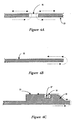
- FIG. 6A One method by which this may be done is shown in Figure 6A.
- an aperture which may preferably be in the form of a slot 16 which can be short in the horizontal direction but long in the direction perpendicular to the plane of the drawing has been provided in the metallic plate 13. Those currents on the under side of the metallic plate 13 which encounter the slot 16 flow through it and then along its upper surface.
- FIG. 6C A further development of this principle is shown in Figure 6C wherein the currents on the underside of the surface of the metallic plate 13 are shown as rounding the end and then following the contour of a thickened metallic section 18 and channel 19 within which the ferromagnetic rod 17 of a label receiving antenna 5 may be placed.
- the surface currents on the three sides of the channel 19 adjacent to the ferromagnetic rod 17 of the label receiving antenna 5, in view of the principle labelled as Ampere's Law as modified by Maxwell, can be said to cause a magnetic field along the axis of the ferromagnetic rod 17, ie. directly into the page, and so provide excitation for the label 4.
- the length of the channel 19 in the direction perpendicular to the page should be significantly greater than the length of the ferromagnetic rod 17 used in the label receiving antenna 5 in that direction so that the flux emerging from the ends of the ferromagnetic rod 17 is not inhibited in completing its necessarily closed path through encountering too soon a metallic conductor whose face is perpendicular to the desired flux path.
- the label receiving antenna 5 takes the form of a coil 12 on a ferromagnetic rod 17 placed in the channel 19 whose axis is orthogonal to the direction of currents induced on the top side of the metallic plate 13 which has an interrogator antenna 9 below the metallic plate 13, the extent of the channel 19 in the axial direction being significantly greater than the length of the ferromagnetic rod 17 of the label receiving antenna 5.
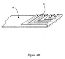
- Figure 6D it is made clear that the direction of the currents on the upper surface of the metallic object need not be the same as or opposite to the direction of the currents on the lower surface.
- a metal plate 13 in which the top section is the folding back of the bottom section, and in which the top section has been furnished with a number of right angled shaped slits 20 to redirect the currents which were initially leftward into an orthogonal direction.
- edges of the metallic plate 13 are made in the form of an extruded section 18, the cross section of which is shown in Figure 7A, into the upper surface of which is machined the series of round holes 21 shown in Figure 7B.
- a simple installation of the label 4 as well as automatic locking in position of and protection against damage to the label 4 may be achieved by shaping the label 4 as shown in that figure.
- a feature of the label 4 shown here is that it contains a long thin ferromagnetic rod 17 which couples well to magnetic fields in the horizontal direction.
- the label 4 contains round locating lugs 22 which anchor it well within the machined slot 23 shown in plan view in Figure 7B and in cross section view in Figure 7A with which airline pallet edges are furnished for the purpose of facilitating locking down of the pallet 14 in flight.
- Yet another feature is the installation at appropriate points on the electronic label 4 of plastic barbs 24 which allow the label 4, in a simple installation operation, to be pressed in to the slot 23 until the barbs 24 expand into the channel 25 below the upper surface of the metal, and lock the label 4 into place.
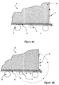
- This design represents a further illustration of the mechanism for transferring current from the bottom side of the metallic plate 13 to its top side, such current being induced on the bottom side by the magnetic field of an interrogator antenna 9 in a direction towards an edge, so that the current on encountering that edge travels up it and back along the top side of the metallic plate 13.
- the current having reached the top side of the metallic plate 13 can if required take a further change in direction shown in Figure 8A.
- the label 4 is placed not on the top side of the metallic plate 13 but on the vertical section of the metallic structure 26 which is constructed above the top side of the metallic plate 13.
- the currents once reaching the top side of the metallic plate 13 can travel vertically upwards on the metallic structure 26 which acts as a conductor and induce magnetic fields which interact with the label 4.
- rollers 15 on which the pallet 14 travels can be made with non-conducting surfaces so that current on the underside of the metallic plate 13 is not interrupted and so that there is thus an expanded range of pallet positions in relation to the rollers 15 at which label reading occurs.
- Figure 8B has been constructed to show as well as those things present in Figure 8A the directions of the associated magnetic field lines associated with the surface currents on the object being identified. It can be seen from this figure that the time varying magnetic flux associated with those magnetic field lines, shown adjacent to and orthogonal to the surface currents in the region of the label 4, will as a consequence of the fundamental principle named above as Faraday's law induce a net potential around the dotted contour shown. As there can be no electric field within the horizontal metal base or the vertical metal body of the pallet 14, there will be an electric field roughly along the portions of that contour which are in air, and that electric field will terminate on oscillating surface electric charges shown in the figure as + and - signs on the metal.
- the oscillating surface change density will be supplied by the oscillating surface current, and will be responsible for a diminution in the amplitude of the oscillating surface current with distance from its source of excitation.
- the displacement current density associated with the above mentioned electric field provides a return path for the surface conduction current. It can be said that in the case of very long objects these surface charges play a part in establishing the coupling from the interrogator antenna 9 to the label receiving antenna 5.
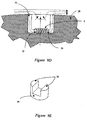
- FIGs 9A to 9D Another situation where electronic labels must be operated in proximity with metal is illustrated in Figures 9A to 9D.
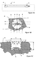
- a label 4 is intended to identify an element of a drilling string 27 in use in the oil industry and for that purpose the solid metal coupling 28 of the drill string 27 shown in Figure 9A has as shown in Figures 9B and 9C had a round hole of diameter D and depth d bored into its surface, and at the bottom of that hole an electronic label 4 excited by a label receiving antenna 5 in the form of a coil 12 wound on a ferromagnetic core 29 has been placed.
- the depth of the hole is considerable, perhaps 25 mm.
- FIGS 9D and 9E a solution to this problem is shown in Figures 9D and 9E. While the electronic label 4 and its ferromagnetic core 29 remain at the bottom of the hole, magnetic flux is encouraged to enter the hole by the installation of ferromagnetic legs 30 shown in Figure 9D which extend from the ferromagnetic core 29 of the label antenna coil 12 upwards to meet the surface of the coupling 28. Although only a small magnetic field H is made to enter the hole, the corresponding magnetic flux density in the ferromagnetic section will be considerably greater than the value it would have if the ferromagnetic legs 30 were not present. The result is an enhancement of both the magnetic field H and magnetic flux density B in the horizontal section of the label receiving antenna 5, with a corresponding enhancement in the wall currents at the bottom of the hole which accompany the enhanced tangential value of the magnetic field.
- coupling to the label 4 is enhanced through the use of a resonant circuit within the label 4 and involving the label receiving antenna 5.
- the resonant frequency is naturally dependent upon the inductance of the label receiving antenna 5 which in turn depends upon the length of the ferromagnetic legs 30 extending upwards to the surface of the coupling. Because of the previously mentioned in-service wear of the coupling 28 the length of those legs 30, which are subject to wear at the same time as the surface of the coupling 28 itself is subject to wear, diminishes in service.
- steps may be taken to preserve as far as possible the continued passage of magnetic field and wall current down the hole without that current suffering diminution through the need to provide a surface charge density on the walls to support an electric flux density which will flow from one wall to another in the space between the ferromagnetic legs as a consequence of Faraday's Law and the existence of a changing magnetic flux within those legs.
- the space within the hole not occupied by the tag circuit or ferromagnetic legs may be filled with a strong dielectric material of low dielectric constant, perhaps of a honeycomb structure.
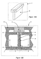
- FIGS 10A and 10B Yet another embodiment of the present invention, suitable for use when the interrogation frequencies are much higher than those which are appropriate for use with the structures discussed up to the present point, is shown in Figures 10A and 10B.
- This embodiment is also suitable for use with metallic airline pallet plate 13 and can make use of some aspects of the slotted extrusion 18, already shown in Figure 7A used in the construction of the edges of such pallets 14.
- the label 4 is shaped externally roughly as shown in Figure 10A and is fitted within the airline pallet 14 in a way illustrated in Figure 10B.
- the rectangular metal tube 32 may be open at the top and may have the electronic label circuit 31 connected between two opposite faces of the rectangular tube 32 or may be closed at the top with the label connected between opposite faces 35 at a point some distance from the closed end.
- the diagram shows the distribution of current in the base of the pallet 14 as a result of its illumination by an electromagnetic field. That current may directly enter the inside of the rectangular metallic tube 32 if a connection is made at is lower end, or may reach the outer surface of the rectangular metallic tube 32 via the capacitance across the thin dielectric layer 34, or may reach the outside of the rectangular metallic tube 32 as a displacement current distributed over its length, so as to create on the outside of the rectangular metallic tube 32 a downward surface conduction current which eventually enters the interior of the rectangular metallic tube 32.
- the rectangular metallic tube 32 can act as an impedance transformer whether or not the electromagnetic field modes within it are evanescent or propagating, and can transform the impedance of the electronic label circuit 31, either in the situation when the rectangular magnetic tube 32 outer wall contacts the rectangular slot 33 in the underside of the pallet 14 or in the situation when it does not, to accomplish a conjugate impedance match between the label impedance and the radiation impedance of the aperture as seen from the connection point to the label circuit 31.
- frictional contacts at microwave frequencies can be unreliable
- the absence of contact between the rectangular metallic tube and the slot in the underside of the pallet 14 is the preferred mode of operation.
- the use of a rectangular tube is a matter of convenience in description, and other shapes permitting electromagnetic fields in their interiors may be employed.
Landscapes
- Physics & Mathematics (AREA)
- Engineering & Computer Science (AREA)
- Electromagnetism (AREA)
- Theoretical Computer Science (AREA)
- General Physics & Mathematics (AREA)
- Health & Medical Sciences (AREA)
- Toxicology (AREA)
- Computer Vision & Pattern Recognition (AREA)
- Artificial Intelligence (AREA)
- General Health & Medical Sciences (AREA)
- Computer Networks & Wireless Communication (AREA)
- Computer Hardware Design (AREA)
- Microelectronics & Electronic Packaging (AREA)
- Near-Field Transmission Systems (AREA)
- Warehouses Or Storage Devices (AREA)
- Manufacture And Refinement Of Metals (AREA)
- Discharge Of Articles From Conveyors (AREA)
- Shielding Devices Or Components To Electric Or Magnetic Fields (AREA)
Claims (40)
- Lesesystem eines elektronischen Etiketts mit:einen Metallobjekt (13),einem elektronischen kodierten Etikett (4) mit einer Antennenspule (12) und einem Träger wenigstens einer Information, wobei das genannte Etikett sich in der Nähe des genannten Metallobjektes (13) befindet,einem Abfrager (1) mit einer Überträgerspule (3) und einer Empfängerspule (6), dadurch gekennzeichnet, dass:das genannte Metallobjekt das genannte Etikett im Wesentlichen gegen den Abfrager (1) abschirmt,und das genannte Metallobjekt (13) darüber hinaus auf seiner Oberseite einen Pfad umfasst, um durch den Abfrager auf einer Seite des Metallobjekts induzierte Oberflächenströme auf die andere Seite durchgehen zu lassen und ein die Antennenspule (12) des Etiketts erregendes Magnetfeld (13C) zu erzeugen.
- Lesesystem eines elektronischen Etikettes gemäß Anspruch 1, dadurch gekennzeichnet, dass die genannte Überträgerspule (3) oder die genannte Empfängerspule (6) einen Magnetkern (9) umfasst.
- Lesesystem eines elektronischen Etiketts gemäß Anspruch 1, dadurch gekennzeichnet, dass in einem Magnetfeld eine Kopplungsverbindung zur Signalgebung vom Abfrager (1) zum Etikett angeordnet ist.
- Lesesystem eines elektronischen Etiketts gemäß Anspruch 1, dadurch gekennzeichnet, dass in einem Magnetfeld eine Kopplungsverbindung zur Signalgebung vom Etikett zum Abfrager (1) angeordnet ist.
- Lesesystem eines elektronischen Etiketts gemäß Anspruch 1, dadurch gekennzeichnet, dass der Abfrager (1) angeordnet ist, um dem Etikett Strom zur Erzeugung einer Antwort auf das Etikett zu liefern.
- Lesesystem eines elektronischen Etiketts gemäß Anspruch 1, dadurch gekennzeichnet, dass das Etikett angeordnet ist, um intermittierend Antworten zu erzeugen.
- Lesesystem eines elektronischen Etiketts gemäß Anspruch 6, dadurch gekennzeichnet, dass Strom für das Etikett vom durch den Überträger während der Dauer, in der das Etikett eine Antwort gibt, gelieferten Strom kommt.
- Lesesystem eines elektronischen Etiketts gemäß Anspruch 3, dadurch gekennzeichnet, dass ein Metallblech (13) zwischen dem Abfrager und das Etikett zwischengeschaltet wird.
- Lesesystem eines elektronischen Etiketts gemäß Anspruch 8, dadurch gekennzeichnet, dass das genannte Metallblech ein erhebliches Ausmaß aufweist.
- Lesesystem eines elektronischen Etiketts gemäß Anspruch 8 mit einer Etikettantennenspule, dadurch gekennzeichnet, dass die Überträger- und Empfängerspulen parallele Achsen haben.
- Lesesystem eines elektronischen Etiketts gemäß einem der vorherigen Ansprüche, dadurch gekennzeichnet, dass das genannte Etikett mit einer auf ein Magnetfeld reagierenden Antenne nahe an den Strömen auf der genannten anderen Seite des genannten Metallobjekts angeordnet ist, so dass die auf ein Magnetfeld reagierende Antenne mit dem Magnetfeld zusammenwirkt, das die genannten Ströme auf der genannten anderen Seite des genannten Metallobjekts begleitet.
- Lesesystem eines elektronischen Etiketts gemäß einem der vorherigen Ansprüche, dadurch gekennzeichnet, dass der genannte Pfad durch Löcher (21) in genanntem Metallobjekt vorgesehen ist.
- Lesesystem eines elektronischen Etiketts gemäß einem der vorherigen Ansprüche, dadurch gekennzeichnet, dass es angeordnet ist, damit die genannten, auf einer Seite des Metallobjekts induzierten Ströme zu einer Kante des genannten Metallobjekts migrieren.
- Lesesystem eines elektronischen Etiketts gemäß einem der vorherigen Ansprüche, dadurch gekennzeichnet, dass es angeordnet ist, damit die Ströme die Richtung wechseln, wenn sie das genannte andere Ende des genannten Metallobjekts erreichen.
- Lesesystem eines elektronischen Etiketts gemäß Anspruch 12, dadurch gekennzeichnet, dass die Kanten der Löcher (21) in dem genannten Metallobjekt lotrecht zur Richtung des genannten induzierten Stroms sind.
- Lesesystem eines elektronischen Etiketts gemäß Anspruch 12, dadurch gekennzeichnet, dass die genannten Löcher in der Richtung eines durch die genannte, ein Magnetfeld erzeugende Antenne erzeugten Magnetfeldes erweitert sind.
- Lesesystem eines elektronischen Etiketts gemäß Anspruch 9, dadurch gekennzeichnet, dass es angeordnet ist, damit der Leiterstrom auf dem genannten Metallobjekt nicht geschlossenen Pfaden fließt.
- Lesesystem eines elektronischen Etiketts gemäß Anspruch 17, dadurch gekennzeichnet, dass es angeordnet ist, damit der Pfad von Strömen, die auf dem genannten Metallobjekt fließen, durch einen Verschiebungsstrom vervollständigt wird.
- Lesesystem eines elektronischen Etiketts gemäß einem der vorherigen Ansprüche, dadurch gekennzeichnet, dass das genannte Etikett in einem Schlitz (23) in einem Metallobjekt untergebracht ist.
- Lesesystem eines elektronischen Etiketts gemäß Anspruch 19, dadurch gekennzeichnet, dass die Länge des genannten Schlitzes in der zu dem Pfad der Ströme im Bereich der Schlitze lotrechten Richtung deutlich größer ist als die Länge der Etikettenspule oder ihres Ferritkerns in der Richtung.
- Lesesystem eines elektronischen Etiketts gemäß Anspruch 19, dadurch gekennzeichnet, dass das gesamte genannte Etikett sich innerhalb der Hauptkontur des genannten Metallobjektes befindet.
- Lesesystem eines elektronischen Etiketts gemäß einem der vorherigen Ansprüche mit einer Etikettantennenspule, dadurch gekennzeichnet, dass die Etikettenspule in ihrem Betriebsfrequenzband mitschwingt.
- Lesesystem eines elektronischen Etiketts gemäß Anspruch 22, dadurch gekennzeichnet, dass die Resonanzfrequenz für die Nähe des Etiketts zum Metall des das Etikett tragenden Objekts angepasst ist.
- Lesesystem eines elektronischen Etiketts gemäß Anspruch 19, dadurch gekennzeichnet, dass das etikettierte Objekt eine Luftfracht-Cargo-Palette ist und das das genannte Etikett in seiner Position durch den Einsatz von in der genannten Palette zum Zweck der Cargo-Verriegelung bereits hergestellten Schlitzen (23) verriegelt wird.
- Lesesystem eines elektronischen Etiketts gemäß Anspruch 24, dadurch gekennzeichnet, dass Widerhaken (24) auf der genannten Etikettenverriegelung es in einen einspringenden Schlitz in der Palette platzieren.
- Lesesystem eines elektronischen Etiketts gemäß Anspruch 24, dadurch gekennzeichnet, dass eine Abfrageantenne parallel zu und zwischen Walzen (15) eines Fördersystems angeordnet sind.
- Lesesystem eines elektronischen Etiketts gemäß Anspruch 26, dadurch gekennzeichnet, dass die Rollen eine nicht leitende Oberfläche oder nicht leitende Lager haben.
- Lesesystem eines elektronischen Etiketts gemäß einem der vorherigen Ansprüche, dadurch gekennzeichnet, dass das genannte Etikett in einem Schlitz in dem genannten Metallobjekt getragen wird.
- Lesesystem eines elektronischen Etiketts gemäß Anspruch 28, dadurch gekennzeichnet, dass die Länge des genannten Schlitzes in der zum Pfad der Ströme im Bereich der Schlitze lotrechten Richtung deutlich größer ist als die Länge der Etikettenspule oder ihres Ferritkerns in der Richtung.
- Lesesystem eines elektronischen Etiketts gemäß Anspruch 28, dadurch gekennzeichnet, dass das ganze genannte Etikett sich innerhalb der Hauptkontur des genannten Metallobjektes befindet.
- Lesesystem eines elektronischen Etiketts gemäß Anspruch 28, mit einer Etikettenantenne, dadurch gekennzeichnet, dass die Etikettenspule in ihrem Betriebsfrequenzband mitschwingt.
- Lesesystem eines elektronischen Etiketts gemäß Anspruch 30, dadurch gekennzeichnet, dass die Resonanzfrequenz für die Nähe des Etiketts zum Metall des das Etikett tragenden Objekts angepasst ist.
- Lesesystem eines elektronischen Etiketts gemäß Anspruch 27, dadurch gekennzeichnet, dass das etikettierte Objekt eine Luftfracht-Cargo-Palette ist und das genannte Etikett in seiner Position durch den Einsatz von zum Zwecke der Cargo-Verriegelung bereits in der genannten Palette hergestellten Schlitzen verriegelt wird.
- Lesesystem eines elektronischen Etiketts gemäß Anspruch 32, dadurch gekennzeichnet, dass Widerhaken auf dem genannten Etikett es in einem einspringenden Schlitz in der Palette verriegeln.
- Lesesystem eines elektronischen Etiketts gemäß Anspruch 27 mit einer Etikettantennenspule, dadurch gekennzeichnet, dass die Etikettenspule angeordnet ist, um durch ein durch Oberflächenströme auf dem Metallobjekt erzeugtes Magnetfeld erregt zu werden.
- Lesesystem eines elektronischen Etiketts gemäß Anspruch 35, dadurch gekennzeichnet, dass das genannte Etikett mit einer auf ein Magnetfeld reagierenden Antenne nahe der Ströme auf der genannten anderen Seite des genannten Metallobjekts angeordnet ist, so dass die genannte auf ein Magnetfeld reagierende Antenne mit dem Magnetfeld zusammenwirkt, das die genannten Ströme auf der genannten anderen Seite des genannten Metallobjekts begleitet.
- Lesesystem eines elektronischen Etiketts gemäß Anspruch 36, dadurch gekennzeichnet, dass der genannte Pfad durch Löcher in dem genannten Metallobjekt vorgesehen ist.
- Lesesystem eines elektronischen Etiketts gemäß Anspruch 35, dadurch gekennzeichnet, dass es angeordnet ist, damit die genannten, auf einer Seite des genannten Metallobjekts induzierten Ströme zu einer Kante des genannten Metallobjekts migrieren.
- Lesesystem eines elektronischen Etiketts gemäß Anspruch 36, dadurch gekennzeichnet, dass die Kanten der Löcher in dem genannten Metall zur Richtung der genannten induzierten Stromrichtung lotrecht sind.
- Verfahren zum Erhalt von Informationen von einem elektronischen Etikett in der Nähe eines Metallobjekts, dadurch gekennzeichnet, dass das Verfahren die folgenden Schritte umfasst:im Wesentlichen Abschirmung des Etiketts von einem Abfrager (1):die Herstellung von induzierten Oberflächenströmen (13 A) auf einer Seite des Metallobjekts durch ein Magnetfeld des Abfragers,Definition eines Pfades auf dem genannten Metallobjekt (13), um den durch den Abfrager auf einer Seite des genannten Metallobjekts induzierten Strömen den Durchgang auf die andere Seite zu erlauben und dadurch ein die Etikettantennenspule (12) erregendes Magnetfeld (13C) zu erzeugen.
Applications Claiming Priority (3)
| Application Number | Priority Date | Filing Date | Title |
|---|---|---|---|
| AUPP4738A AUPP473898A0 (en) | 1998-07-20 | 1998-07-20 | Metal screened electronic labelling system |
| AUPP473898 | 1998-07-20 | ||
| PCT/AU1999/000587 WO2000005675A1 (en) | 1998-07-20 | 1999-07-20 | Metal screened electronic labelling system |
Publications (3)
| Publication Number | Publication Date |
|---|---|
| EP1114389A1 EP1114389A1 (de) | 2001-07-11 |
| EP1114389A4 EP1114389A4 (de) | 2004-06-16 |
| EP1114389B1 true EP1114389B1 (de) | 2005-06-22 |
Family
ID=3808976
Family Applications (1)
| Application Number | Title | Priority Date | Filing Date |
|---|---|---|---|
| EP99932547A Expired - Lifetime EP1114389B1 (de) | 1998-07-20 | 1999-07-20 | Metallabgeschirmtes elektronisches auszeichnungssystem |
Country Status (10)
| Country | Link |
|---|---|
| US (1) | US6956481B1 (de) |
| EP (1) | EP1114389B1 (de) |
| JP (1) | JP4523159B2 (de) |
| CN (1) | CN1318174A (de) |
| AT (1) | ATE298445T1 (de) |
| AU (2) | AUPP473898A0 (de) |
| CA (1) | CA2343750A1 (de) |
| DE (1) | DE69925921T2 (de) |
| ES (1) | ES2245110T3 (de) |
| WO (1) | WO2000005675A1 (de) |
Families Citing this family (68)
| Publication number | Priority date | Publication date | Assignee | Title |
|---|---|---|---|---|
| GB0005038D0 (en) | 2000-03-03 | 2000-04-26 | Mckechnie Components Limited | Container |
| JP3711026B2 (ja) | 2000-07-17 | 2005-10-26 | 株式会社ハネックス | Rfidタグの設置構造及びrfidタグの設置方法及びrfidタグの通信方法 |
| AU2000268175A1 (en) * | 2000-09-06 | 2002-03-22 | R.T.S., Spol. S R.O. | Equipment for the wireless numeric identification of metallic, namely ferromagnetic bodies |
| CN1224933C (zh) * | 2002-12-10 | 2005-10-26 | 陈伟 | 电子货架标签系统及电子标签和它们处理信号的方法 |
| US7083083B2 (en) * | 2004-04-27 | 2006-08-01 | Nagraid S.A. | Portable information carrier with transponders |
| US20060098673A1 (en) * | 2004-11-09 | 2006-05-11 | Alcatel | Input queue packet switch architecture and queue service discipline |
| FR2884681B1 (fr) * | 2005-04-15 | 2007-06-22 | St Microelectronics Sa | Antenne pour etiquette electronique |
| US7443362B2 (en) * | 2005-07-19 | 2008-10-28 | 3M Innovative Properties Company | Solenoid antenna |
| JP4720348B2 (ja) * | 2005-08-04 | 2011-07-13 | パナソニック株式会社 | Rf−idリーダーライター装置用アンテナ及びそれを用いたrf−idリーダーライター装置並びにrf−idシステム |
| JP5226178B2 (ja) * | 2005-09-13 | 2013-07-03 | 株式会社スマート | 金属埋込センサシステム |
| JP4673171B2 (ja) * | 2005-09-13 | 2011-04-20 | 株式会社インテグレイテッドビジネス | 垂直磁界センサシステム |
| CN1979534B (zh) * | 2005-11-30 | 2011-02-23 | 上海衡准智能科技有限公司 | 一种立体式电子标签 |
| US7519328B2 (en) | 2006-01-19 | 2009-04-14 | Murata Manufacturing Co., Ltd. | Wireless IC device and component for wireless IC device |
| US9064198B2 (en) | 2006-04-26 | 2015-06-23 | Murata Manufacturing Co., Ltd. | Electromagnetic-coupling-module-attached article |
| JP4956152B2 (ja) * | 2006-11-21 | 2012-06-20 | 株式会社スマート | センサ・タグの多面影像方式 |
| US8235299B2 (en) | 2007-07-04 | 2012-08-07 | Murata Manufacturing Co., Ltd. | Wireless IC device and component for wireless IC device |
| WO2009008296A1 (ja) | 2007-07-09 | 2009-01-15 | Murata Manufacturing Co., Ltd. | 無線icデバイス |
| JP4873079B2 (ja) | 2007-07-17 | 2012-02-08 | 株式会社村田製作所 | 無線icデバイス及び電子機器 |
| CN102915462B (zh) | 2007-07-18 | 2017-03-01 | 株式会社村田制作所 | 无线ic器件 |
| WO2009110381A1 (ja) | 2008-03-03 | 2009-09-11 | 株式会社村田製作所 | 無線icデバイス及び無線通信システム |
| JP5239499B2 (ja) * | 2008-05-13 | 2013-07-17 | 戸田工業株式会社 | 複合磁性体アンテナ及びrfタグ、該複合磁性体アンテナ又はrfタグを設置した金属部品、金属工具 |
| CN103295056B (zh) | 2008-05-21 | 2016-12-28 | 株式会社村田制作所 | 无线ic器件 |
| WO2009145007A1 (ja) | 2008-05-26 | 2009-12-03 | 株式会社村田製作所 | 無線icデバイスシステム及び無線icデバイスの真贋判定方法 |
| EP2320519B1 (de) | 2008-08-19 | 2017-04-12 | Murata Manufacturing Co., Ltd. | Drahtloses ic-element und herstellungsverfahren dafür |
| WO2010055945A1 (ja) | 2008-11-17 | 2010-05-20 | 株式会社村田製作所 | アンテナ及び無線icデバイス |
| CN103500873B (zh) | 2009-01-09 | 2016-08-31 | 株式会社村田制作所 | 无线ic器件及无线ic模块 |
| CN102301528B (zh) | 2009-01-30 | 2015-01-28 | 株式会社村田制作所 | 天线及无线ic器件 |
| JP5510450B2 (ja) | 2009-04-14 | 2014-06-04 | 株式会社村田製作所 | 無線icデバイス |
| CN103022661B (zh) | 2009-04-21 | 2014-12-03 | 株式会社村田制作所 | 电子设备及天线装置的谐振频率设定方法 |
| CN102577646B (zh) | 2009-09-30 | 2015-03-04 | 株式会社村田制作所 | 电路基板及其制造方法 |
| JP5304580B2 (ja) | 2009-10-02 | 2013-10-02 | 株式会社村田製作所 | 無線icデバイス |
| WO2011052310A1 (ja) | 2009-10-27 | 2011-05-05 | 株式会社村田製作所 | 送受信装置及び無線タグ読み取り装置 |
| CN102549838B (zh) | 2009-11-04 | 2015-02-04 | 株式会社村田制作所 | 通信终端及信息处理系统 |
| WO2011055701A1 (ja) | 2009-11-04 | 2011-05-12 | 株式会社村田製作所 | 通信端末及び情報処理システム |
| WO2011062238A1 (ja) | 2009-11-20 | 2011-05-26 | 株式会社村田製作所 | アンテナ装置及び移動体通信端末 |
| WO2011077877A1 (ja) | 2009-12-24 | 2011-06-30 | 株式会社村田製作所 | アンテナ及び携帯端末 |
| WO2011108340A1 (ja) | 2010-03-03 | 2011-09-09 | 株式会社村田製作所 | 無線通信モジュール及び無線通信デバイス |
| JP5403146B2 (ja) | 2010-03-03 | 2014-01-29 | 株式会社村田製作所 | 無線通信デバイス及び無線通信端末 |
| JP5477459B2 (ja) * | 2010-03-12 | 2014-04-23 | 株式会社村田製作所 | 無線通信デバイス及び金属製物品 |
| JP5370581B2 (ja) | 2010-03-24 | 2013-12-18 | 株式会社村田製作所 | Rfidシステム |
| WO2011122163A1 (ja) | 2010-03-31 | 2011-10-06 | 株式会社村田製作所 | アンテナ装置及び無線通信デバイス |
| JP5376060B2 (ja) | 2010-07-08 | 2013-12-25 | 株式会社村田製作所 | アンテナ及びrfidデバイス |
| GB2537773A (en) | 2010-07-28 | 2016-10-26 | Murata Manufacturing Co | Antenna apparatus and communication terminal instrument |
| WO2012020748A1 (ja) | 2010-08-10 | 2012-02-16 | 株式会社村田製作所 | プリント配線板及び無線通信システム |
| WO2012043432A1 (ja) | 2010-09-30 | 2012-04-05 | 株式会社村田製作所 | 無線icデバイス |
| CN105226382B (zh) | 2010-10-12 | 2019-06-11 | 株式会社村田制作所 | 天线装置及终端装置 |
| CN102971909B (zh) | 2010-10-21 | 2014-10-15 | 株式会社村田制作所 | 通信终端装置 |
| JP5510560B2 (ja) | 2011-01-05 | 2014-06-04 | 株式会社村田製作所 | 無線通信デバイス |
| JP5304956B2 (ja) | 2011-01-14 | 2013-10-02 | 株式会社村田製作所 | Rfidチップパッケージ及びrfidタグ |
| TWI530703B (zh) * | 2011-02-23 | 2016-04-21 | 宏碁股份有限公司 | 電子裝置及其定位方法 |
| JP5370616B2 (ja) | 2011-02-28 | 2013-12-18 | 株式会社村田製作所 | 無線通信デバイス |
| JP5630566B2 (ja) | 2011-03-08 | 2014-11-26 | 株式会社村田製作所 | アンテナ装置及び通信端末機器 |
| CN103081221B (zh) | 2011-04-05 | 2016-06-08 | 株式会社村田制作所 | 无线通信器件 |
| WO2012141070A1 (ja) | 2011-04-13 | 2012-10-18 | 株式会社村田製作所 | 無線icデバイス及び無線通信端末 |
| JP5569648B2 (ja) | 2011-05-16 | 2014-08-13 | 株式会社村田製作所 | 無線icデバイス |
| WO2013008874A1 (ja) | 2011-07-14 | 2013-01-17 | 株式会社村田製作所 | 無線通信デバイス |
| JP5333707B2 (ja) | 2011-07-15 | 2013-11-06 | 株式会社村田製作所 | 無線通信デバイス |
| WO2013011865A1 (ja) | 2011-07-19 | 2013-01-24 | 株式会社村田製作所 | アンテナモジュール、アンテナ装置、rfidタグおよび通信端末装置 |
| CN203553354U (zh) | 2011-09-09 | 2014-04-16 | 株式会社村田制作所 | 天线装置及无线器件 |
| JP5344108B1 (ja) | 2011-12-01 | 2013-11-20 | 株式会社村田製作所 | 無線icデバイス及びその製造方法 |
| WO2013115019A1 (ja) | 2012-01-30 | 2013-08-08 | 株式会社村田製作所 | 無線icデバイス |
| JP5464307B2 (ja) | 2012-02-24 | 2014-04-09 | 株式会社村田製作所 | アンテナ装置および無線通信装置 |
| CN104487985B (zh) | 2012-04-13 | 2020-06-26 | 株式会社村田制作所 | Rfid标签的检查方法及检查装置 |
| CN105048060A (zh) * | 2015-07-23 | 2015-11-11 | 爱康普科技(大连)有限公司 | 一种rfid标签读取器的抗干扰天线 |
| CN106483266B (zh) * | 2015-08-26 | 2019-02-12 | 深圳市燃气集团股份有限公司 | 一种可检测可燃气体的地下电子标签探测仪 |
| CN105428808B (zh) * | 2015-12-09 | 2018-01-19 | 广东欧珀移动通信有限公司 | 一种收发多频段无线信号的天线和终端 |
| AU2019428486B2 (en) | 2019-02-08 | 2025-10-30 | Allflex Australia Pty Ltd | Electronic animal tag reader |
| CN113099709A (zh) * | 2021-04-06 | 2021-07-09 | 海宁普拉斯电子科技有限公司 | 一种可屏蔽周围磁场干扰的电子标签识别器 |
Family Cites Families (17)
| Publication number | Priority date | Publication date | Assignee | Title |
|---|---|---|---|---|
| US4622543A (en) * | 1984-03-22 | 1986-11-11 | Anderson Iii Philip M | Surveillance system having acoustic magnetomechanical marker |
| US4647917A (en) * | 1984-03-26 | 1987-03-03 | Allied Corporation | Article control system having coded magnetomechanical marker |
| JPS6374230A (ja) * | 1986-09-17 | 1988-04-04 | Mitsubishi Electric Corp | 地中通信装置 |
| NL8700369A (nl) * | 1987-02-16 | 1988-09-16 | Nedap Nv | Werkwijze voor het plaatsen van een elektronische responder in een omgeving van metaal. |
| DE69230171T2 (de) * | 1991-04-03 | 2000-04-13 | Integrated Silicon Design Pty. Ltd., Adelaide | Warensortiersystem |
| GB2258712B (en) | 1991-08-16 | 1994-11-30 | Mitsuboshi Seisakusho Co Ltd | Steering shaft and manufacturing method therefor |
| JP2873983B2 (ja) * | 1991-11-22 | 1999-03-24 | 株式会社レイディック | 鋼製ロッドによる地中情報収集方式 |
| EP0677887A1 (de) * | 1994-04-13 | 1995-10-18 | Texas Instruments Incorporated | Eingebauter Chip-Transponder mit Antenne |
| DE4414290A1 (de) * | 1994-04-23 | 1995-10-26 | Messer Griesheim Gmbh | System zur maschinenlesbaren Identifikation von Behältern |
| DE4425736C2 (de) * | 1994-07-21 | 1997-12-18 | Micro Sensys Gmbh | Einbauschale für Daten- oder Codeträger |
| FR2723654B1 (fr) * | 1994-08-10 | 1996-10-11 | Gemplus Card Int | Etiquette electronique et systeme pour l'identification sans contact d'objets, notamment d'objets metalliques. |
| US5565847A (en) * | 1994-11-23 | 1996-10-15 | International Business Machines Corporation | Magnetic tag using acoustic or magnetic interrogation |
| DE19510458A1 (de) * | 1995-03-24 | 1996-09-26 | L & S Logistic & Software Gmbh | Transponderbefestigung |
| US5736929A (en) | 1996-06-07 | 1998-04-07 | International Business Machines Corporation | System for concealed serialization utilizing a soft magnetic antitheft element |
| JP3585142B2 (ja) * | 1996-06-13 | 2004-11-04 | 日本電信電話株式会社 | ワイヤレスicタグの設置装置 |
| AUPO055296A0 (en) * | 1996-06-19 | 1996-07-11 | Integrated Silicon Design Pty Ltd | Enhanced range transponder system |
| JPH1049639A (ja) * | 1996-08-02 | 1998-02-20 | Shinwa Kogyo Kk | 埋設物認識方法とその埋設標識体 |
-
1998
- 1998-07-20 AU AUPP4738A patent/AUPP473898A0/en not_active Abandoned
-
1999
- 1999-07-20 AT AT99932547T patent/ATE298445T1/de not_active IP Right Cessation
- 1999-07-20 WO PCT/AU1999/000587 patent/WO2000005675A1/en not_active Ceased
- 1999-07-20 DE DE69925921T patent/DE69925921T2/de not_active Expired - Lifetime
- 1999-07-20 EP EP99932547A patent/EP1114389B1/de not_active Expired - Lifetime
- 1999-07-20 CA CA002343750A patent/CA2343750A1/en not_active Abandoned
- 1999-07-20 CN CN99808939A patent/CN1318174A/zh active Pending
- 1999-07-20 ES ES99932547T patent/ES2245110T3/es not_active Expired - Lifetime
- 1999-07-20 JP JP2000561581A patent/JP4523159B2/ja not_active Expired - Fee Related
- 1999-07-20 AU AU48892/99A patent/AU4889299A/en not_active Abandoned
- 1999-07-20 US US09/744,145 patent/US6956481B1/en not_active Expired - Lifetime
Also Published As
| Publication number | Publication date |
|---|---|
| WO2000005675A1 (en) | 2000-02-03 |
| EP1114389A1 (de) | 2001-07-11 |
| JP4523159B2 (ja) | 2010-08-11 |
| EP1114389A4 (de) | 2004-06-16 |
| ES2245110T3 (es) | 2005-12-16 |
| CA2343750A1 (en) | 2000-01-03 |
| DE69925921D1 (de) | 2005-07-28 |
| DE69925921T2 (de) | 2006-05-11 |
| CN1318174A (zh) | 2001-10-17 |
| AUPP473898A0 (en) | 1998-08-13 |
| ATE298445T1 (de) | 2005-07-15 |
| US6956481B1 (en) | 2005-10-18 |
| JP2002521757A (ja) | 2002-07-16 |
| AU4889299A (en) | 2000-02-14 |
Similar Documents
| Publication | Publication Date | Title |
|---|---|---|
| EP1114389B1 (de) | Metallabgeschirmtes elektronisches auszeichnungssystem | |
| AU634789B2 (en) | Electromagnetic energy transmission and detection system | |
| US5523749A (en) | Identification system for simultaneously interrogated labels | |
| US7142163B2 (en) | Loop antenna device | |
| US5764127A (en) | Inductive transmitters for conductor location | |
| CA2284600A1 (en) | Apparatus for magnetically decoupling an rfid tag | |
| US10177608B2 (en) | System providing inductive transmission of power and data through a permeable conductive barrier layer | |
| US3911389A (en) | Magnetic gradient vehicle detector | |
| US20130161389A1 (en) | RFID-Reader sowie Vorrichtung mit einem RFID-Reader | |
| EP0285188B1 (de) | Verfahren zur Anbringung eines elektronischen Antwortgebers in einem oder in der Nähe eines elektrisch leitenden Gegenstandes und elektrisch leitender Gegenstand, versehen mit einem solchen Antwortgeber | |
| EP1064568A1 (de) | Abfragegerät zum abfragen einer rfld | |
| US20030107377A1 (en) | Metal detector | |
| EP0771478B1 (de) | Dampfungsglied | |
| Cole | A study of factors affecting the design of EPC antennas & readers for supermarket shelves | |
| US3839700A (en) | Traffic sensor | |
| EP2541564A1 (de) | Drahtlose Energieübertragung | |
| JP3113882B2 (ja) | 近距離通信用アンテナ及びその使用方法 | |
| US12500627B2 (en) | NFC loop antenna in the vicinity of a metallic structure, and method for operating this antenna | |
| US20030122674A1 (en) | Electronic marker for metallic valve box covers | |
| JP2003107146A (ja) | 電磁波レーダ装置 | |
| JP2000350302A (ja) | 非接触給電システムのレール継ぎ手 | |
| EP0017682A3 (de) | Verfahren und System für geophysikalische Induktions-Untersuchungen |
Legal Events
| Date | Code | Title | Description |
|---|---|---|---|
| PUAI | Public reference made under article 153(3) epc to a published international application that has entered the european phase |
Free format text: ORIGINAL CODE: 0009012 |
|
| 17P | Request for examination filed |
Effective date: 20010220 |
|
| AK | Designated contracting states |
Kind code of ref document: A1 Designated state(s): AT BE CH CY DE DK ES FI FR GB GR IE IT LI LU MC NL PT SE |
|
| RAP1 | Party data changed (applicant data changed or rights of an application transferred) |
Owner name: GEMPLUS TAG AUSTRALIA PTY. LTD. |
|
| A4 | Supplementary search report drawn up and despatched |
Effective date: 20040507 |
|
| RIC1 | Information provided on ipc code assigned before grant |
Ipc: 7G 06K 7/08 B Ipc: 7G 06K 19/077 A |
|
| 17Q | First examination report despatched |
Effective date: 20040802 |
|
| RAP1 | Party data changed (applicant data changed or rights of an application transferred) |
Owner name: GEMPLUS |
|
| GRAP | Despatch of communication of intention to grant a patent |
Free format text: ORIGINAL CODE: EPIDOSNIGR1 |
|
| GRAS | Grant fee paid |
Free format text: ORIGINAL CODE: EPIDOSNIGR3 |
|
| GRAA | (expected) grant |
Free format text: ORIGINAL CODE: 0009210 |
|
| AK | Designated contracting states |
Kind code of ref document: B1 Designated state(s): AT BE CH CY DE DK ES FI FR GB GR IE IT LI LU MC NL PT SE |
|
| PG25 | Lapsed in a contracting state [announced via postgrant information from national office to epo] |
Ref country code: NL Free format text: LAPSE BECAUSE OF FAILURE TO SUBMIT A TRANSLATION OF THE DESCRIPTION OR TO PAY THE FEE WITHIN THE PRESCRIBED TIME-LIMIT Effective date: 20050622 Ref country code: LI Free format text: LAPSE BECAUSE OF FAILURE TO SUBMIT A TRANSLATION OF THE DESCRIPTION OR TO PAY THE FEE WITHIN THE PRESCRIBED TIME-LIMIT Effective date: 20050622 Ref country code: FI Free format text: LAPSE BECAUSE OF FAILURE TO SUBMIT A TRANSLATION OF THE DESCRIPTION OR TO PAY THE FEE WITHIN THE PRESCRIBED TIME-LIMIT Effective date: 20050622 Ref country code: CH Free format text: LAPSE BECAUSE OF FAILURE TO SUBMIT A TRANSLATION OF THE DESCRIPTION OR TO PAY THE FEE WITHIN THE PRESCRIBED TIME-LIMIT Effective date: 20050622 Ref country code: BE Free format text: LAPSE BECAUSE OF FAILURE TO SUBMIT A TRANSLATION OF THE DESCRIPTION OR TO PAY THE FEE WITHIN THE PRESCRIBED TIME-LIMIT Effective date: 20050622 Ref country code: AT Free format text: LAPSE BECAUSE OF FAILURE TO SUBMIT A TRANSLATION OF THE DESCRIPTION OR TO PAY THE FEE WITHIN THE PRESCRIBED TIME-LIMIT Effective date: 20050622 |
|
| REG | Reference to a national code |
Ref country code: GB Ref legal event code: FG4D |
|
| REG | Reference to a national code |
Ref country code: CH Ref legal event code: EP |
|
| PG25 | Lapsed in a contracting state [announced via postgrant information from national office to epo] |
Ref country code: LU Free format text: LAPSE BECAUSE OF NON-PAYMENT OF DUE FEES Effective date: 20050720 Ref country code: IE Free format text: LAPSE BECAUSE OF NON-PAYMENT OF DUE FEES Effective date: 20050720 Ref country code: CY Free format text: LAPSE BECAUSE OF FAILURE TO SUBMIT A TRANSLATION OF THE DESCRIPTION OR TO PAY THE FEE WITHIN THE PRESCRIBED TIME-LIMIT Effective date: 20050720 |
|
| REG | Reference to a national code |
Ref country code: IE Ref legal event code: FG4D |
|
| REF | Corresponds to: |
Ref document number: 69925921 Country of ref document: DE Date of ref document: 20050728 Kind code of ref document: P |
|
| PG25 | Lapsed in a contracting state [announced via postgrant information from national office to epo] |
Ref country code: MC Free format text: LAPSE BECAUSE OF NON-PAYMENT OF DUE FEES Effective date: 20050731 |
|
| PG25 | Lapsed in a contracting state [announced via postgrant information from national office to epo] |
Ref country code: SE Free format text: LAPSE BECAUSE OF FAILURE TO SUBMIT A TRANSLATION OF THE DESCRIPTION OR TO PAY THE FEE WITHIN THE PRESCRIBED TIME-LIMIT Effective date: 20050922 Ref country code: GR Free format text: LAPSE BECAUSE OF FAILURE TO SUBMIT A TRANSLATION OF THE DESCRIPTION OR TO PAY THE FEE WITHIN THE PRESCRIBED TIME-LIMIT Effective date: 20050922 Ref country code: DK Free format text: LAPSE BECAUSE OF FAILURE TO SUBMIT A TRANSLATION OF THE DESCRIPTION OR TO PAY THE FEE WITHIN THE PRESCRIBED TIME-LIMIT Effective date: 20050922 |
|
| PG25 | Lapsed in a contracting state [announced via postgrant information from national office to epo] |
Ref country code: PT Free format text: LAPSE BECAUSE OF FAILURE TO SUBMIT A TRANSLATION OF THE DESCRIPTION OR TO PAY THE FEE WITHIN THE PRESCRIBED TIME-LIMIT Effective date: 20051129 |
|
| NLV1 | Nl: lapsed or annulled due to failure to fulfill the requirements of art. 29p and 29m of the patents act | ||
| REG | Reference to a national code |
Ref country code: ES Ref legal event code: FG2A Ref document number: 2245110 Country of ref document: ES Kind code of ref document: T3 |
|
| REG | Reference to a national code |
Ref country code: CH Ref legal event code: PL |
|
| ET | Fr: translation filed | ||
| REG | Reference to a national code |
Ref country code: IE Ref legal event code: MM4A |
|
| PLBE | No opposition filed within time limit |
Free format text: ORIGINAL CODE: 0009261 |
|
| STAA | Information on the status of an ep patent application or granted ep patent |
Free format text: STATUS: NO OPPOSITION FILED WITHIN TIME LIMIT |
|
| 26N | No opposition filed |
Effective date: 20060323 |
|
| PGFP | Annual fee paid to national office [announced via postgrant information from national office to epo] |
Ref country code: GB Payment date: 20120629 Year of fee payment: 14 |
|
| PGFP | Annual fee paid to national office [announced via postgrant information from national office to epo] |
Ref country code: IT Payment date: 20120628 Year of fee payment: 14 Ref country code: FR Payment date: 20120806 Year of fee payment: 14 Ref country code: ES Payment date: 20120716 Year of fee payment: 14 |
|
| GBPC | Gb: european patent ceased through non-payment of renewal fee |
Effective date: 20130720 |
|
| REG | Reference to a national code |
Ref country code: FR Ref legal event code: ST Effective date: 20140331 |
|
| PG25 | Lapsed in a contracting state [announced via postgrant information from national office to epo] |
Ref country code: GB Free format text: LAPSE BECAUSE OF NON-PAYMENT OF DUE FEES Effective date: 20130720 |
|
| PG25 | Lapsed in a contracting state [announced via postgrant information from national office to epo] |
Ref country code: IT Free format text: LAPSE BECAUSE OF NON-PAYMENT OF DUE FEES Effective date: 20130720 Ref country code: FR Free format text: LAPSE BECAUSE OF NON-PAYMENT OF DUE FEES Effective date: 20130731 |
|
| REG | Reference to a national code |
Ref country code: ES Ref legal event code: FD2A Effective date: 20150710 |
|
| PG25 | Lapsed in a contracting state [announced via postgrant information from national office to epo] |
Ref country code: ES Free format text: LAPSE BECAUSE OF NON-PAYMENT OF DUE FEES Effective date: 20130721 |
|
| PGFP | Annual fee paid to national office [announced via postgrant information from national office to epo] |
Ref country code: DE Payment date: 20180620 Year of fee payment: 20 |
|
| REG | Reference to a national code |
Ref country code: DE Ref legal event code: R071 Ref document number: 69925921 Country of ref document: DE |