EP1114218B1 - Siebvorrichtung - Google Patents
Siebvorrichtung Download PDFInfo
- Publication number
- EP1114218B1 EP1114218B1 EP99948750A EP99948750A EP1114218B1 EP 1114218 B1 EP1114218 B1 EP 1114218B1 EP 99948750 A EP99948750 A EP 99948750A EP 99948750 A EP99948750 A EP 99948750A EP 1114218 B1 EP1114218 B1 EP 1114218B1
- Authority
- EP
- European Patent Office
- Prior art keywords
- screen
- connection
- screen apparatus
- screening device
- clip
- Prior art date
- Legal status (The legal status is an assumption and is not a legal conclusion. Google has not performed a legal analysis and makes no representation as to the accuracy of the status listed.)
- Expired - Lifetime
Links
- 238000007873 sieving Methods 0.000 title description 8
- 230000003014 reinforcing effect Effects 0.000 claims abstract description 71
- 125000006850 spacer group Chemical group 0.000 claims abstract description 52
- 239000000725 suspension Substances 0.000 claims description 4
- 230000009471 action Effects 0.000 claims description 3
- 230000000284 resting effect Effects 0.000 claims description 2
- 238000006073 displacement reaction Methods 0.000 claims 1
- 230000037431 insertion Effects 0.000 claims 1
- 238000003780 insertion Methods 0.000 claims 1
- 238000010008 shearing Methods 0.000 claims 1
- 238000012216 screening Methods 0.000 abstract description 192
- 230000002787 reinforcement Effects 0.000 description 77
- 238000013461 design Methods 0.000 description 16
- 238000004519 manufacturing process Methods 0.000 description 15
- 230000006870 function Effects 0.000 description 7
- 230000000694 effects Effects 0.000 description 5
- 230000003321 amplification Effects 0.000 description 4
- 238000010276 construction Methods 0.000 description 4
- 238000003199 nucleic acid amplification method Methods 0.000 description 4
- 230000000295 complement effect Effects 0.000 description 3
- 239000000835 fiber Substances 0.000 description 3
- 239000000463 material Substances 0.000 description 3
- 230000006978 adaptation Effects 0.000 description 2
- 230000008901 benefit Effects 0.000 description 2
- 230000015572 biosynthetic process Effects 0.000 description 2
- 230000001419 dependent effect Effects 0.000 description 2
- 230000003993 interaction Effects 0.000 description 2
- 238000000034 method Methods 0.000 description 2
- 230000008569 process Effects 0.000 description 2
- 230000003068 static effect Effects 0.000 description 2
- 238000003466 welding Methods 0.000 description 2
- 241001295925 Gegenes Species 0.000 description 1
- 230000002411 adverse Effects 0.000 description 1
- 230000008859 change Effects 0.000 description 1
- 230000002950 deficient Effects 0.000 description 1
- 230000002349 favourable effect Effects 0.000 description 1
- 239000003292 glue Substances 0.000 description 1
- 210000004013 groin Anatomy 0.000 description 1
- 238000009434 installation Methods 0.000 description 1
- 238000012986 modification Methods 0.000 description 1
- 230000004048 modification Effects 0.000 description 1
- 230000000149 penetrating effect Effects 0.000 description 1
- 230000035515 penetration Effects 0.000 description 1
- 238000012805 post-processing Methods 0.000 description 1
- 238000012545 processing Methods 0.000 description 1
- 238000011084 recovery Methods 0.000 description 1
- 230000009467 reduction Effects 0.000 description 1
- 238000009420 retrofitting Methods 0.000 description 1
- 238000000926 separation method Methods 0.000 description 1
- 229910000679 solder Inorganic materials 0.000 description 1
- 230000007480 spreading Effects 0.000 description 1
- 238000003892 spreading Methods 0.000 description 1
- 238000012549 training Methods 0.000 description 1
- 238000012546 transfer Methods 0.000 description 1
- 230000007704 transition Effects 0.000 description 1
- 238000012800 visualization Methods 0.000 description 1
Images


Classifications
-
- D—TEXTILES; PAPER
- D21—PAPER-MAKING; PRODUCTION OF CELLULOSE
- D21D—TREATMENT OF THE MATERIALS BEFORE PASSING TO THE PAPER-MAKING MACHINE
- D21D5/00—Purification of the pulp suspension by mechanical means; Apparatus therefor
- D21D5/02—Straining or screening the pulp
- D21D5/16—Cylinders and plates for screens
-
- Y—GENERAL TAGGING OF NEW TECHNOLOGICAL DEVELOPMENTS; GENERAL TAGGING OF CROSS-SECTIONAL TECHNOLOGIES SPANNING OVER SEVERAL SECTIONS OF THE IPC; TECHNICAL SUBJECTS COVERED BY FORMER USPC CROSS-REFERENCE ART COLLECTIONS [XRACs] AND DIGESTS
- Y10—TECHNICAL SUBJECTS COVERED BY FORMER USPC
- Y10T—TECHNICAL SUBJECTS COVERED BY FORMER US CLASSIFICATION
- Y10T29/00—Metal working
- Y10T29/49—Method of mechanical manufacture
- Y10T29/496—Multiperforated metal article making
- Y10T29/49604—Filter
Definitions
- the invention relates to a screening device, which especially for fiber suspensions in the paper industry is determined and for example in sorters, such as Pressure sorters or the like is used.
- Such a screening device comprises a screening surface forming, essentially cylindrical sieve device, which in the form of a slotted screen mat or in the form of a Sieve plate with drilled or milled / sawn sieve slots can be trained.
- a screening device of a high static and exposed to dynamic stress in usually a spacer element of the cylindrical screen device assigned, and the cylindrical screening device with the spacer is spaced radially a reinforcing device supported, which for example can be designed as a reinforcing jacket.
- the axial Ends of the screening device closing elements for example be provided in the form of end rings.
- the respective final element becomes a design with the reinforcement device and the sieve device welded, the screen device being assembled first and then the amplification device from positioned outside over the screening device and then attached becomes.
- screening devices In the usual use of screening devices is mainly the screening device is exposed to severe wear, while the reinforcement device is often a very long one Has lifespan. Through the welded connection of the screening device with spacer and reinforcement device Formation of the screening device must, however, after wear Screening device replaced the entire screening device become what is expensive and time-consuming.
- a sorter with a screen basket in which over separate bearing points axially spaced in the longitudinal direction of the strainer basket in the form of bearing rings, a support for the screen basket in connection with assigned counter-bearing elements on the sorting housing.
- a frictional clamping connection comprising wedge strips and the like the strainer basket is determined via the bearing points.
- additional seals are provided for the clamp connection.
- the intended Support construction is on the one hand very complex and extensive many individual parts. Furthermore, the axially spaced bearing points only radial forces, but no torsional forces are absorbed.
- strainer basket is only supported directly on the sorter housing so that an adaptation to differently designed sieve baskets or sieve devices only by a corresponding change in the main support function fulfilling sorter housing is possible because in addition to the sorter housing provided reinforcement devices are missing, against which the Sieve basket could support.
- US-A-4 954 294 and US-A-5 023 986 is a strainer basket construction with a modular structure consisting of several small screen cylinder elements known in ring form.
- the individual screen cylinder modules are interchangeable and are marked by notches positively connected with reinforcement rings.
- the axial end rings are formed by a large number of tension rods braced against each other. The axial tie rods will be at the same time through holes in the reinforcement rings guided.
- Sieve cylinders are offered by J & L Fiber Services, Inc. where a variety of short rod-shaped elements positively positioned in the grooves of reinforcing rings and is fixed in position by means of tie rods. Installation is time consuming and expensive. To defective and worn rod-shaped elements of the screening device To replace, the entire screen cylinder must be in its individual parts be disassembled.
- a sieve basket is known from EP-A-0 724 037, in the case of the profile bars with form-fitting rings get connected.
- the invention aims to provide a screening device which especially for fiber suspensions in the paper industry is intended to provide which at a constructive simple interpretation an economic reuse of those that are not so exposed to wear Parts of the screening device, such as the reinforcing device, allowed in a cost-effective manner, the Screening device and the reinforcing device reliable and dynamically and statically resilient.
- a screening device in particular for fiber suspensions in the paper industry, provided which forms a sieve surface has essentially cylindrical screening device, which is spaced on a radial by means of spacers arranged reinforcement device is supported, wherein the screening device is interchangeable and non-positively fixed to the reinforcement device , in which further the screening device and the reinforcing device by means of a frictional clamp connection are releasably connected and the clamp connection the screening device by means of an axial Cone seat effect on the reinforcement device.
- the actual sieve device which is the sieve surface forms, detach from the reinforcement device again, when the heavily used screening device is worn out.
- the amplification device can be after Replacing the sieving device again with the sieving device deploy.
- the inventive design of the screening device makes use of the knowledge that the screening device with the screening surface, if necessary Interaction with spacer elements mainly only actual screening and / or visualization function realized, while the actual carrying function for the screening device and for inserting the screening device into the respective Machine taken over by the reinforcement device becomes.
- the invention allows multiple Use of the reinforcement device while the Intended use of the sieve device highly susceptible to wear Screening device with the essentially cylindrical screen surface as a whole and can be exchanged uniformly is.
- the core idea is Invention to be seen in that not the individual sieve elements the screening device, such as in parallel arranged rod-shaped sieve elements, in case of wear exchanged and replaced, but that the Entire screening device, which is a prefabricated unit forms, is interchangeable, and that in particular the actual Support function and the corresponding adjustment of the Sieving device to the machine, like a sorter, over the amplification device is carried out separately and manufactured and designed independently of the screening device can be.
- the screening device according to the invention is thus omitted an integral connection, such as a welded connection, between reinforcement device and sieve device. Due to the interchangeability of excessive wear inclined screening device and by reuse the reinforcement device is achieved in the invention designed screening device a reduction in Material usage. Furthermore, the screening device can be opened inexpensive way to get them back and the unsealed ones Parts can be reused. Let too sieve devices according to the invention with clearly restore and retrieve less time, there in the recovery and restoration not all for the original manufacture of the screening device required manufacturing steps performed must be, but some of them can be omitted. In particular, the screening device according to the invention allows also the realization of a modular construction with all the advantages of a modular system in terms of Manufacturing and warehousing.
- screening devices in standard sizes as well assigned reinforcement devices in standard sizes prefabricate, which then according to the application requirements assembled and assembled into a screening device can be.
- the invention also allows Screening device possibly an inexpensive Retrofitting if a due to changing requirements Screening device of another design, for example, to achieve better performance results should be used without that the sieve device itself is no longer worn is useful.
- the intended frictional clamp connection is Screening device with the essentially cylindrical screen surface fully and reliably positioned fixed to the reinforcement device.
- the clamp connection in the invention Screening device can also be realized in such a way that the screening device by means of an axial conical seat effect is fixed to the reinforcement device.
- the outer surfaces act the spacer elements of the screen surface Screening device, which is conical in the axial direction
- the clamp connection between screening devices with spacers and reinforcement realized by means of an axial press cone seat connection becomes.
- the sieve device forms a sieve insert with an essentially cylindrical inner surface as a screen surface and an axially conical External surface, which is formed by spacer elements.
- sieve insert becomes the formation of the sieve device according to the invention in a correspondingly conical in axial Reinforcement device designed in the direction, for example used in the form of a reinforcing jacket, and through the conically opposing seats the clamp connection of the sieve device or sieve insert and reinforcement device manufactured.
- the clamp connection is established the screening device by means of frictional engagement, preferably wedge action on the reinforcing device firmly.
- frictional engagement preferably wedge action on the reinforcing device firmly.
- clamping devices and / or clamping elements with frictional engagement, preferably wedge action for manufacture the non-positive connection used.
- the clamping connection can preferably be clamping elements include which to form the clamp connection radially movable in the direction of the reinforcing device are. With such a configuration it is achieved that the type, number and arrangement of the clamping elements Production of the clamp connection according to the Requirements such as size and intended use or the like, can be selected.
- the clamp connection Clamping elements used which are I-shaped in cross section are trained.
- One cross leg is against the Screening device and the other against the spacer elements on.
- Such a clamping element can preferably be in the form one running in the axial direction of the screening device Groin be trained. With such an embodiment becomes the sieve device with sieve surface and spacer elements compared to the reinforcement device in such a way braced that the screen sections by the clamping element the screen area with the assigned spacer elements in Expanded circumferential direction and against the reinforcing device be tense.
- clamping element is in shape a bar running in the axial direction is formed, such a terminal block in the axial direction of one end to the other end of the screening device driven between the screen sections of the screening device and thereby the screening device against the reinforcing device be stretched under spread.
- the clamping elements are wedge elements trained which is a radial tightening direction have to form the clamp connection.
- Wedge tightening connection can be in the interaction of wedge element and spacer by appropriate training of reciprocally cooperating wedge suit bevels become.
- the clamping element Be T-shaped, and the cross leg of the "T” can rest on the sieve.
- the T-shaped in this embodiment Clamping element in the form of an axial direction of the screening device or do this at an angle or spiral Rail or bar should be designed so that one a suitable surface pressure for the one to be manufactured Receives clamp connection at the screening device.
- the T-shaped clamping element can be in two parts be designed, one on the screen surface of the screening device resting cross leg part and a spacer penetrating longitudinal leg part may be provided can. Fixing and tensioning on non-positive Way with the reinforcement device can then, for example done via a screw connection. This can one prefabricates several for the non-positive connection Use individual parts and partly standard parts to to be able to realize favorable manufacturing costs.
- the clamping elements of the clamp connection are by means of at least one tightening element can be moved in the radial direction.
- the tightening element can be in the form of a screw, rivet or Bolt connection with the clamping element for radial Movement of the same work together.
- the respective tightening element is preferably after manufacture the clamp connection on the reinforcement device fixable.
- ways of defining such as welding or the like can also be done at which, for example, that on the amplification device specified tightening elements at the transition areas or reworked in another way.
- Also can optionally in the manufacture of the clamp connection The resulting joints are integrally fused become.
- the tightening element in the screening device according to the invention passes at least partially through the reinforcement device in the radial direction.
- the pull-through element preferably penetrates the reinforcement device completely and for the Establishment of the clamp connection is the tightening element from the outside of the reinforcement device applied.
- a closing element preferably detachable, with the reinforcing device connected, whereby the screening device in is positioned in the axial direction.
- This final element can be designed in the form of a ring, such as an intrusion be, and the end element can be on the machine side Adapt requirements as a kind of adapter piece and lay out.
- the reinforcing device can for example in the form of a reinforcement jacket independently from the machine adaptation for the intended Use of the screening device can be designed so that the manufacture of the same is simplified.
- the respective Adjustment then takes place via the closing elements or End rings, which act as a kind of adapter for each Intended use in the desired machine, such as a sorter.
- this can essentially cylindrical screen surface of the screening device from a slotted screen mat and / or portions thereof be, or the substantially cylindrical screen surface can from a sieve plate and / or sections thereof be formed.
- Screening device all the usual designs of Screening devices and screen elements, such as slotted screen mats or appropriately rounded sieve plates are used, in which by means of mechanical removal processing appropriate sieve openings are cut.
- the Screening device spiral screen slots or Screen gaps on the screen surface formed by the screen device to have.
- the reinforcement device can be in the form of a reinforcement jacket be formed, which with passages is provided and referred to as a so-called backup jacket becomes.
- the reinforcing device on the outside additionally with reinforcement rings be provided.
- a screening device has at least one closing element, for example in the form of an end ring on or has axial end faces, so in the invention Interpretation of the closure element accessible from both sides on the Reinforcement device before placing the screening device be welded with the spacers.
- the invention allows the screening device assembled from the inside out when assembling the parts and can be built, taking to create the weld to connect the closure element and Reinforcement device accessible from both sides is and therefore a high quality of the heavily used Weld seam connection can be ensured. Also can notch effects on such a weld joint reduce this accessibility from both sides. This can create a permanent and strong connection of closure element and reinforcement device be ensured.
- the screening device with the spacer elements is then after the connection of the final element and reinforcement device arranged and applied, and then finally the frictional connection to fix sieve with spacer and Reinforcement device manufactured.
- the screening device with the spacer elements is preferred with the interposition of an insert tape compared to the End element positioned in the axial direction.
- an insert tape can be another weld for fixing and axial positioning of the sieve device avoid with the spacers. This too assembly and disassembly are even easier further, and tolerances in the axial direction of the Screening device effective with the help of such an insert tape compensate.
- the screening device It is essential in the screening device according to the invention therefore, that one is an inexpensive reuse of components of a screening device that are not as susceptible to wear with the simplest possible structure of the screening device receives what the screening device with the spacers by means of a frictional clamp connection without a material connection to the reinforcement device is set. This can lead to wear Screening device can be replaced without the entire screening device must be destroyed and disassembled. Even if terminating elements at the axial ends of the screening device are provided, they are only cohesive with the reinforcement device but not with connected to the screening device and the spacer elements. As a result, the screening device can, for example, by a partial dismantling of the screening device can be replaced, wherein the connection of closure elements and reinforcing device is maintained unchanged.
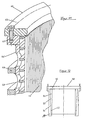
- Figure 1 relates to a first embodiment a sieve device designated overall by 1.
- the Screening device 1 comprises a screen device 2, spacer elements 3, a reinforcing device 4, and an axial, frontal end element 5.
- the screening device 2 comprises rod-shaped sieve elements 6, which also act as sieve rods are referred to, and which are essentially parallel and spaced axially parallel to the screening device 1 in this way are arranged that between two adjacent rod-shaped sieve elements 6 sieve slots 7 or sieve gaps 7 are formed.
- the rod-shaped sieve elements 6 are in a corresponding manner Specified on the spacers 3, which preferably axially spaced in the circumferential direction of the screening device 2 run.
- the spacer elements are expedient 3 ring-shaped.
- the rod-shaped sieve elements 6 or the sieve bars form together with the spacer elements 3 a screening device 2, the inner surface 8 of the screening device 1 is a substantially cylindrical Sieving surface 9 forms which the sieve slots or Sieve column 7 contains.
- the front end elements 5, which in the form of a End ring is formed is in the illustrated embodiment according to Figure 1 via a welded connection 10 connected to the reinforcement device 4, which expediently designed in the form of a reinforcing jacket which corresponding breakthroughs are not shown) Has.
- the weld joint 10 is on both sides accessible and therefore can be reliably Weld seam with the desired quality, for example in shape create a double fillet weld 10 as shown.
- the sieve device 1 is from the inside to the assembly assembled and assembled on the outside.
- the screening device 2 is by means of a frictional Clamping connection on the reinforcement device 4 set such that in the finished state Sieving device 2 is not relative to the reinforcing device 4 can twist.
- Wedge connection 11 is provided as a clamp connection.
- the wedge connection 11 is in the example shown as one running in the axial direction of the screening device 1 Wedge rail formed.
- an insert tape 12 between the end element 5 and the assigned screening device 2 is provided, which at the same time in the assembled state, the welded joint 10 in Direction to the inside of the screening device 1 covered.
- the clamping connection designed as a wedge connection 11 becomes the screening device 2 with the spacer elements 3 frictionally with the reinforcement device 4 in the form of a reinforcement jacket or backup jacket releasably connected.
- the screen surface 9 of the screen device 2 is radially spaced from the reinforcement device 4 arranged by means of the spacer elements 3.
- the screening device 2 When the screening device 2 is in the intended use state is used up or due to signs of wear unfavorable performance parameters are achieved, can thanks to the design of the screening device according to the invention 1 provided frictional clamp connection the screening device 2 with the spacer elements 3 expanded as a unit and replaced with a new one become.
- the clamp connection is designed for this for example in the form of a wedge connection 11, solved, and the screening device 2 can be removed without the Reinforcement device 4 significantly damaged or even gets destroyed.
- Screening device 1 again as intended in a corresponding Machine, such as a sorter (not shown), be used.
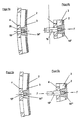
- Figure 2 shows a wedge connection 11 ', which one or comprises a plurality of wedge elements 14, which are in the radial tightening direction directly with the spacer 3 of the screening device 2 work together, in the spacers 3 corresponding complementary wedge-shaped openings 15 are provided.
- a screw 16 By means of a screw 16 the wedge element 14 in the radial tightening direction, in FIG. 2 towards the left, and this will cause the Screening device 2 with the spacer elements 3 frictionally connected to the reinforcement device 4 by means of clamps.
- Figure 3 shows a frictional clamp connection in Form of a circular connection 11 ".
- the tightening element is here a step screw 17 formed, which in a corresponding threaded bore of the engages each wedge element 14 '.
- the stepped screw 17 on the reinforcement device 4 for example be determined by the head of the stepped screw 17 separated and ground the surface and, if necessary a material connection of step screw 17 and reinforcing device 4 is created.
- Even in the embodiment 3 is the clamp connection Radial tightening direction for establishing the clamp connection of screening device 2 and reinforcing device 4th
- a bolt 19 as a tightening element used, which in a similar manner as in Figure 3 a wedge element 14 "cooperates, and after the Applying force in the direction of arrow F, i.e. with a tractive force, separated and for example by means of a Welded connection 20 fixed to the reinforcement device 4 becomes. The protruding part of the bolt 19 can then separated and ground if necessary.
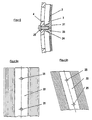
- FIGS. 5a and 5b A further embodiment variant is shown in FIGS. 5a and 5b a clamp connection by means of clamping elements 14 "'.
- This clamp connection is also a bolt there designated 19 'is used, the but in contrast to the design form according to Figures 4a and 4b for tightening not with a tractive force but with a compressive force is applied.
- the determination of the Bolt 19 'as a tightening element after manufacture of the non-positive Connection on the reinforcement device 4 can in the same or similar manner as in Figures 4a and 4b shown.
- the T-shaped Clamping element 21 in the form of an axial direction the screening device 1 or at an angle to it Rail 22 are formed.
- the cross leg 23 of the cross-sectionally T-shaped clamping element 21 rests the screen surface 9 of the screen device 2 on and in a radial Direction is followed by a wedge 24, which for example, as shown in Figure 6, with a complementary designed wedge surface of a corresponding wedge-shaped opening 15 "in the spacer element 3 the screening device 2 can work together.
- a suit element is similar to that described above Embodiments provided a screw 25.
- FIG 7 is a two-part embodiment Clamping connection of screen device 2 and reinforcement device 4 shown.
- the two-part clamping element 26 comprises a cover strip-shaped first part 27, which bears against the screen surface 9 of the screen device 2.
- This first part 27 has, as shown, a thread for Receiving a screw 28 serving as a tightening element.
- an expansion bar 29 Between the inside of the reinforcement device 4 and the assigned inside of the cover strip-shaped first Part 27 is an expansion bar 29 with a through hole arranged.
- a clamping element 30 used which is I-shaped in cross section is.
- One cross leg 31 lies against the screen surface 9 the screening device 2.
- the other cross leg 32 of the Cross-section I-shaped clamping element 30 lies against that corresponding spacer 3.
- Such in the form a bar formed and I-shaped in cross section Clamping element 30 is expediently of an axial Introduced side of the screening device 1 ago and the screening device 2 will cooperate in the circumferential direction spread with the clamping element 30 and so frictionally connected to the reinforcement device 4 with a clamp connection.
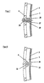
- the screening device 40 is a screening device 42, spacer elements 43 and a reinforcing device 44.
- a terminating element 45 which, for example ring-shaped in the manner of an end ring is releasably connected to the reinforcing device 44.
- Pins 46 are used for the releasable connection according to FIG used, which in the circumferential direction of the closure element 45 are preferably arranged regularly distributed.
- the end element 45 with respect to the screening device 42 facing surface formed such that the end element 45 at the same time an axial positioning of the screening device 42 allowed.
- FIG. 11 shows a further embodiment variant of an overall with 40 'designated sieve.
- the end element 45 'and Reinforcement device 44 ' shown, which of axially extending Screws 47 is formed.
- These screws too 47 are preferably at regular angular intervals
- Closing element 45 ' arranged and engage accordingly assigned threaded openings in part of the reinforcement device 44 'a.
- This end element 45 ' is designed so that by appropriate interpretations the sieve device 42 can thereby be positioned axially can.
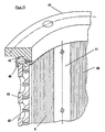
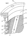
- FIG 12 shows an alternative embodiment of a frictional clamp connection for a screening device, which is labeled with a total of 50 there. at this embodiment is a wedge seat clamp connection realized.
- the screening device 50 includes like that a screening device explained above 52, spacer elements 53, a reinforcing device 54 and a preferably detachable with the reinforcing device 54 connected end element 55.
- the sieve device 52 of the sieve device is an embodiment 50 designed in the form of a sieve insert, wherein for example the spacer elements 53 of the screening device 52 form a conical seat surface 56 in the axial direction.
- the reinforcing device 54 has a complementary one for this conical seat surface course 57 in such a way that when inserting the sieve device designed as a sieve insert 52 over the conical seats 56, 57 a frictional clamp connection with the reinforcing device 54 is made such that the screening device 52 by means of the frictional clamp connection over the conical seats 56, 57 in the form of a Cone seating effect is determined. This will then Screening device 52 on the clamp connection on the Reinforcement device 54 set so that the sieve device 52 is not relative to the reinforcement device 54 can twist when ready for use.
- the end member 55 may be similar as shown in Figure 11, expediently detachable with of the reinforcing device 54.
- FIG 13 is another application example of an overall shown with 60 designated screening device.
- the rod-shaped sieve elements 66 spiral sieve slots 67.
- a screening device 62 can also be described the sieving device 60 by means of a frictional clamp connection with the. Reinforcement device 64 connected become.
- the correspondingly explained above Embodiments of the clamp connections and the like, can in the same or a similar way at a such a screening device 60, if necessary, with corresponding ones Variations are used.
- the screening devices 2, 42, 52 and 62 as Slotted screen mats and / or sections thereof are shown are which rod-shaped sieve elements or sieve rods 6 or 66, the screening devices 2, 42, 52 or 62 also from a sieve plate, not shown and / or sections thereof are formed.
Landscapes
- Engineering & Computer Science (AREA)
- Mechanical Engineering (AREA)
- Paper (AREA)
- Combined Means For Separation Of Solids (AREA)
- Beans For Foods Or Fodder (AREA)
- Noodles (AREA)
- Non-Silver Salt Photosensitive Materials And Non-Silver Salt Photography (AREA)
- Eye Examination Apparatus (AREA)
Description
- Fig. 1
- eine perspektivische Ausschnittsansicht einer Siebvorrichtung nach der Erfindung,
- Fig. 2
- eine schematische Ausschnitts-Querschnittsansicht einer Klemmschlußverbindung als reibschlüssige Verbindung mittels eines Keilelements, welches in radialer Anzugsrichtung unmittelbar mit einem Distanzelement zusammenwirkt,
- Fig. 3
- eine schematische Ausschnitts-Querschnittsansicht zur Verdeutlichung einer abgewandelten Ausführungsform einer Klemmschlußverbindung mit einem Keilelement nach Figur 2, wobei als Anzugselement eine Stufenschraube eingesetzt wird,
- Fig. 4a und Fig. 4b,
- jeweils eine schematische AusschnittsQuerschnittsansicht zur Verdeutlichung einer Bolzenanordnung für ein Anzugselement einer Klemmschlußverbindung bei der erfindungsgemäßen Siebvorrichtung,
- Fig. 5a und Fig. 5b
- jeweils eine schematische Ausschnittsansicht mit einer Nietanordnung als Anzugselement für eine Klemmschlußverbindung bei der erfindungsgemäßen Siebvorrichtung,
- Fig. 6
- eine schematische Ausschnitts-Querschnittsansicht zur Verdeutlichung einer Ausführungsvariante eines Klemmelements, welches T-förmig ausgebildet ist, wobei der Querschenkel des "T" bei der Herstellung der Klemmschlußverbindung flächig gegen die Siebeinrichtung anliegt,
- Fig. 7
- eine schematische Ausschnitts-Querschnittsansicht zur Verdeutlichung einer weiteren Ausführungsform einer Klemmschlußverbindung mit zweiteiligem Klemmelement,
- Fig. 8a und Fig. 8b
- jeweils eine schematische Ansicht einer Ausführungsvariante, bei welcher ein T-förmig ausgebildetes Klemmelement in Form einer in axialer Richtung der Siebvorrichtung oder unter einem Winkel hierzu verlaufenden Schiene ausgebildet ist,
- Fig. 9
- eine schematische Ausschnitts-Querschnittsansicht zur Verdeutlichung einer Ausführungsvariante einer kraftschlüssigen Verbindung mittels einer im Querschnitt I-förmig ausgebildeten Leiste,
- Fig. 10
- eine perspektivische Ausschnittsansicht einer Siebvorrichtung mit einem lösbaren an einem axialen Ende vorgesehenen Abschlußelement,
- Fig. 11
- eine Figur 10 ähnliche Ansicht einer Ausführungsvariante einer lösbaren Verbindung von stirnseitigem Abschlußelement an der Verstärkungseinrichtung bei einer Auslegungsform einer erfindungsgemäßen Siebvorrichtung,
- Fig. 12
- eine schematische Schnittansicht einer alternativen Ausführungsform einer reibschlüssigen Klemmschlußverbindung von Siebeinrichtung und Verstärkungseinrichtung bei einer erfindungsgemäßen Auslegungsform einer Siebvorrichtung, und
- Fig. 13
- eine perspektivische schematische Ausschnittsansicht einer Siebvorrichtung mit einer spiralförmigen Orientierung von Siebschlitzen an der Siebfläche der Siebeinrichtung.
- 1
- Siebvorrichtung insgesamt in Figur 1
- 2
- Siebeinrichtung insgesamt
- 3
- Distanzelemente
- 4
- Verstärkungseinrichtung
- 5
- Abschlußelement
- 6
- Stabförmiges Siebelement oder Siebstäbe
- 7
- Siebschlitze
- 8
- Innenfläche der Siebeinrichtung 1
- 9
- Siebfläche
- 10
- Schweißverbindung
- 11
- Keilverbindung in Figur 1
- 11'
- Keilverbindung in Figur 2
- 11"
- Keilverbindung in Figur 3
- 12
- Einlegeband
- 14
- Keilelement in Figur 2
- 14', 14", 14'", 14"
- jeweils Keilelemente
- 15
- Keilförmige Öffnung in Figur 2
- 15"
- Keilförmige Öffnung in Figur 2
- 16
- Schraube
- 17
- Stufenschraube
- 19
- Bolzen
- 20
- Schweißverbindung
- 21
- T-förmiges Klemmelement in Figur 6
- 22
- Schiene
- 23
- Querschenkel
- 24
- Anzugskeil
- 25
- Schraube
- 26
- Klemmelement in figur 7
- 27
- Deckleistenförmiges erstes Teil
- 28
- Schraube
- 29
- Spreizleiste
- 30
- Klemmelement in Figur 9
- 31
- Querschenkel
- 32
- Querschenkel
- 40
- Siebvorrichtung in Figur 10
- 42
- Siebeinrichtung
- 43
- Distanzelemente
- 44
- Verstärkungseinrichtung
- 44'
- Verstärkungseinrichtung in Figur 11
- 45
- Abschlußelement
- 45'
- Abschlußelement in Figur 11
- 46
- Stifte
- 47
- Schrauben
- 48
- Verstärkungsringe
- 50
- Siebvorrichtung insgesamt in Figur 12
- 52
- Siebeinrichtung
- 53
- Distanzelement
- 54
- Verstärkungseinrichtung
- 55
- Abschlußelement
- 56
- Konische Sitzfläche von Siebeinrichtung 52
- 57
- Konische Sitzfläche an Verstärkungseinrichtung 54
- 60
- Siebvorrichtung insgesamt in Figur 13
- 62
- Siebeinrichtung
- 64
- Verstärkungseinrichtung
- 66
- Stabförmige Siebelemente
- 67
- Siebschlitze
Claims (26)
- Siebvorrichtung, insbesondere für Faserstoffsuspensionen in der Papierindustrie, mit einer eine Siebfläche (9) bildenden, im wesentlichen zylindrischen Siebeinrichtung (2; 42; 52; 62), welche auf einer radial mittels Distanzelementen (3; 43; 53;) beabstandet angeordneten, Verstärkungseinrichtung (4; 44; 44'; 54; 64) abgestützt ist, wobei die Siebeinrichtung (2; 42; 52; 62) als Einheit auswechselbar und kraftschlüssig an der Verstärkungseinrichtung (4; 44; 44', 54; 64) festgelegt ist und wobei die Siebeinrichtung (2; 42; 52; 62) und die Verstärkungseinrichtung (4; 44; 44'; 54, 64) mittels einer reibschlüssigen Klemmschlußverbindung lösbar verbunden sind, dadurch gekennzeichnet, daß die Klemmschlußverbindung die Siebeinrichtung (52) mittels einer axialen Kegelsitzwirkung an der Verstärkungseinrichtung (54) festlegt.
- Siebvorrichtung nach Anspruch 1, dadurch gekennzeichnet, daß die Siebeinrichtung (2; 42; 52; 62) im Zusammenwirken mit den Distanzelementen (3; 43; 53) durch die Klemmschlußverbindung an der Verstärkungseinrichtung (4; 44; 44'; 54; 64) festgelegt ist.
- Siebvorrichtung nach Anspruch 1 oder 2, dadurch gekennzeichnet, daß die Klemmschlußverbindung Klemmelemente (14; 14'; 14"; 14"'; 21; 26; 30) umfaßt, welche zur Bildung der Klemmschlußverbindung radial in Richtung der Verstärkungseinrichtung (4; 44; 44'; 54; 64) bewegbar sind.
- Siebvorrichtung nach Anspruch 3, dadurch gekennzeichnet, daß das Klemmelement (30) im Querschnitt I-förmig ausgebildet ist, der eine Querschenkel (31) gegen die Siebeinrichtung (2) und der andere (32) gegen die Verstärkungseinrichtung (3) anliegt.
- Siebvorrichtung nach Anspruch 3, dadurch gekennzeichnet, daß die Klemmelemente (14; 14'; 14"; 14"'; 21; 26) der Klemmschlußverbindung durch die Siebeinrichtung (2) gehen und an der Verstärkungseinrichtung (4) festlegbar sind.
- Siebvorrichtung nach einem der Ansprüche 3 bis 5, dadurch gekennzeichnet, daß mehrere Klemmelemente (14; 14'; 14"; 14"'; 21; 26) auf einer Achslinie der Siebvorrichtung (1; 40; 40'; 50; 60) angeordnet sind.
- Siebvorrichtung nach Anspruch 1, 2, 3 oder 6, dadurch gekennzeichnet, daß die Klemmelemente als Keilelemente (14; 14'; 14"; 14"') mit radialer Anzugsrichtung zur Bildung der Klemmschlußverbindung ausgebildet sind.
- Siebvorrichtung nach Anspruch 7, dadurch gekennzeichnet, daß die Keilanzugsverbindung im Zusammenwirken von Keilelement (14; 14', 14"; 14"') und Verstärkungseinrichtung (4; 44; 44'; 54; 64) gebildet wird.
- Siebvorrichtung nach Anspruch 1, 2, 3 oder 6, dadurch gekennzeichnet, daß das Klemmelement (21) T-förmig ausgebildet ist und der Querschenkel (23) des "T" auf der Siebfläche (9) der Siebeinrichtung (2) aufliegt.
- Siebvorrichtung nach Anspruch 9, dadurch gekennzeichnet, daß das T-förmige Klemmelement (21) in Form einer in Achsrichtung der Siebvorrichtung (2) oder hierzu unter einem Winkel oder spiralförmig verlaufenden Schiene (22) ausgebildet ist.
- Siebvorrichtung nach Anspruch 9 oder 10, dadurch gekennzeichnet, daß das T-förmig ausgebildete Klemmelement (26) zweiteilig ausgebildet ist.
- Siebvorrichtung nach Anspruch 11, dadurch gekennzeichnet, daß das zweiteilig ausgebildete Klemmelement (26) ein auf der Siebfläche (9) der Siebeinrichtung (2) aufliegendes Querschenkelteil (27) und ein das Distanzelement (3) durchsetzendes Längsschenkelteil (29) umfaßt.
- Siebvorrichtung nach einem der Ansprüche 3 bis 12, dadurch gekennzeichnet, daß die Klemmelemente (14; 14'; 14"; 14"'; 21; 26; 30) der Klemmschlußverbindung mittels wenigstens eines Anzugselements in Form einer Schraub-, Niet- oder Bolzenverbindung radial bewegbar sind.
- Siebvorrichtung nach Anspruch 13, dadurch gekennzeichnet, daß jedes Anzugselement nach Herstellung der Klemmschlußverbindung an der Verstärkungseinrichtung (4; 44; 44'; 54; 64) festlegbar ist.
- Siebvorrichtung nach Anspruch 14, dadurch gekennzeichnet, daß das Anzugselement wenigstens teilweise die Verstärkungseinrichtung (4; 44; 44'; 54; 64) in radialer Richtung durchsetzt.
- Siebvorrichtung nach einem der Ansprüche 13 bis 15, dadurch gekennzeichnet, daß das Anzugselement von der Außenseite der Verstärkungseinrichtung (4; 44; 44'; 54; 64) zur Bildung der Klemmschlußverbindung kraftbeaufschlagbar ist.
- Siebvorrichtung nach einem der vorangehenden Ansprüche, dadurch gekennzeichnet, daß zur axialen Fixierung an wenigstens einer axialen Stirnseite der Siebvorrichtung (2; 42; 52; 62) ein Abschlußelement (5; 45; 45'; 55), vorzugsweise lösbar, mit der Verstärkungseinrichtung (4; 44; 44'; 54; 64) verbunden ist, welches die Siebeinrichtung (2; 42; 52; 62) in axialer Richtung positioniert.
- Siebvorrichtung nach Anspruch 17, dadurch gekennzeichnet, daß die lösbare Verbindung als Stiftverbindung (46) ausgebildet ist.
- Siebvorrichtung nach Anspruch 17, dadurch gekennzeichnet, daß die lösbare Verbindung als Schraubverbindung (47) ausgebildet ist.
- Siebvorrichtung nach einem der vorangehenden Ansprüche, dadurch gekennzeichnet, daß die Siebeinrichtung (2; 42; 52; 62) von einer Spaltsiebmatte und/oder Abschnitten derselben gebildet wird.
- Siebvorrichtung nach einem der Ansprüche 1 bis 19, dadurch gekennzeichnet, daß die Siebeinrichtung (2; 42; 52; 62) von einer Siebplatte und/oder Abschnitten derselben gebildet wird.
- Siebvorrichtung nach Anspruch 20 oder 21, dadurch gekennzeichnet, daß die Siebeinrichtung (62) spiralförmige verlaufende Siebschlitze (61) an der Siebfläche (9) hat.
- Siebvorrichtung nach einem der vorangehenden Ansprüche, dadurch gekennzeichnet, daß das Verstärkungseinrichtung (4; 44; 44', 54; 64) als mit Durchgängen versehener Verstärkungsmantel ausgebildet ist.
- Siebvorrichtung nach einem der vorangehenden Ansprüche mit wenigstens einem Abschlußelement (5; 45; 45'; 55) an der axialen Stirnseite der Siebvorrichtung (2; 42; 52; 62), dadurch gekennzeichnet, daß das Abschlußelement (5; 45; 45', 55) beidseitig zugänglich an der Verstärkungseinrichtung (4; 44; 44'; 54; 64) vor dem Anordnen der Siebeinrichtung (2; 42; 52; 62) mit dem Distanzelement (3; 43; 53) ist.
- Siebvorrichtung nach Anspruch 24, dadurch gekennzeichnet, daß die Siebeinrichtung (2, 62) mit Distanzelementen (3) unter Zwischenlage eines Einlegebands (12) gegenüber dem stirnseitigen Abschlußelement (5) in axialer Richtung positioniert ist.
- Siebvorrichtung nach einem der vorangehenden Ansprüche, dadurch gekennzeichnet, daß zusätzlich eine scherkraftübertragende Verstiftung zur Vermeidung einer Relativverschiebung in Umfangsrichtung von Siebeinrichtung (2; 42; 52; 62) mit Distanzelementen (3; 43; 53) und Verstärkungseinrichtung (4; 44; 44'; 54, 64) vorgesehen ist.
Applications Claiming Priority (3)
| Application Number | Priority Date | Filing Date | Title |
|---|---|---|---|
| DE19842042A DE19842042A1 (de) | 1998-09-14 | 1998-09-14 | Siebvorrichtung |
| DE19842042 | 1998-09-14 | ||
| PCT/EP1999/006801 WO2000015901A1 (de) | 1998-09-14 | 1999-09-14 | Siebvorrichtung |
Publications (2)
| Publication Number | Publication Date |
|---|---|
| EP1114218A1 EP1114218A1 (de) | 2001-07-11 |
| EP1114218B1 true EP1114218B1 (de) | 2003-05-02 |
Family
ID=7880918
Family Applications (1)
| Application Number | Title | Priority Date | Filing Date |
|---|---|---|---|
| EP99948750A Expired - Lifetime EP1114218B1 (de) | 1998-09-14 | 1999-09-14 | Siebvorrichtung |
Country Status (6)
| Country | Link |
|---|---|
| US (1) | US6579458B2 (de) |
| EP (1) | EP1114218B1 (de) |
| AT (1) | ATE239126T1 (de) |
| CA (1) | CA2344477A1 (de) |
| DE (2) | DE19842042A1 (de) |
| WO (1) | WO2000015901A1 (de) |
Cited By (1)
| Publication number | Priority date | Publication date | Assignee | Title |
|---|---|---|---|---|
| DE102013010959B3 (de) * | 2013-07-01 | 2014-08-07 | Andritz Fiedler Gmbh | Siebvorrichtung |
Families Citing this family (23)
| Publication number | Priority date | Publication date | Assignee | Title |
|---|---|---|---|---|
| FR2794478B1 (fr) * | 1999-06-04 | 2001-08-03 | Lamort E & M | Tamis cylindrique, notamment pour la pate a papier |
| BR0100425C2 (pt) * | 2001-01-12 | 2003-12-02 | Daniel Villares Lenz Cesar | Filtro autolimpante |
| CA2802168A1 (en) * | 2001-04-16 | 2002-10-24 | J & L Fiber Services, Inc. | Screen cylinder and method |
| FI119387B (fi) * | 2003-08-22 | 2008-10-31 | Metso Paper Inc | Menetelmä sihtisylinterin valmistamiseksi ja sihtisylinteri |
| WO2005032691A1 (en) * | 2003-10-03 | 2005-04-14 | Weatherford Australia Pty Limited | Improved screen nozzle |
| ITVI20040139A1 (it) * | 2004-06-10 | 2004-09-10 | Comer Spa | Metodo per la fabbricazione di cestelli filtranti di fibre in sospensione acquosa e cestello filtrante fabbricato mediante detto metodo |
| FR2873596B1 (fr) * | 2004-07-27 | 2006-09-22 | Weatherford Lamb | Centrifugeuse avec une bride de serrage crantee |
| WO2006119614A1 (en) * | 2005-05-09 | 2006-11-16 | Hetu Marc-Andre | Screen basket with replaceable profiled bars |
| DE102007015901B4 (de) | 2007-04-02 | 2023-07-20 | Andritz Fiedler Gmbh | Siebvorrichtung |
| ITVI20070209A1 (it) * | 2007-07-31 | 2009-02-01 | Comer Spa | Cestello filtrante perfezionato per fibre in sospensione acquosa |
| EP2222916B1 (de) * | 2007-11-14 | 2015-06-24 | Kadant Canada Corp. | Siebkorb |
| US8192634B2 (en) * | 2009-07-13 | 2012-06-05 | Gilles Stephen R | Centrifugal basket assembly with segmented dam and method |
| DE102014011679A1 (de) | 2013-08-20 | 2015-02-26 | Andritz Fiedler Gmbh | Profilierter Siebstab und Siebvorrichtung aus profilierten Siebstäben |
| SE537441C2 (sv) * | 2013-08-29 | 2015-04-28 | Bomill Ab | Trumma, en maskin som innefattar en sådan trumma, och ett förfarande för tillverkning av en sådan trumma |
| DE102013226184A1 (de) * | 2013-12-17 | 2015-06-18 | Voith Patent Gmbh | Siebzylinder |
| US10076716B2 (en) * | 2014-08-22 | 2018-09-18 | Gl&V Usa Inc. | Pinned fly ring for rotary drum washer and method of manufacture |
| WO2016045876A1 (en) * | 2014-09-23 | 2016-03-31 | Koninklijke Philips N.V. | Modular sieve and juicing apparatus. |
| DE102015003020B3 (de) | 2015-03-06 | 2016-03-03 | Andritz Fiedler Gmbh | Stabsiebkorb |
| US20200164290A1 (en) * | 2017-06-07 | 2020-05-28 | Sabic Global Technologies B.V. | Rotary vacuum filter, method, and use |
| DE102018007790A1 (de) * | 2017-10-16 | 2019-04-18 | Andritz Fiedler Gmbh | Diskontinuierlich betriebene Zentrifuge |
| EP3586697A1 (de) * | 2018-06-25 | 2020-01-01 | Koninklijke Philips N.V. | Lebensmittelzubereitungsvorrichtung |
| DE102018007294A1 (de) * | 2018-09-14 | 2020-03-19 | Guntram Krettek | Verfahren zum Fixieren eines Bleches und damit hergestellte Filtereinrichtung |
| CN119237302B (zh) * | 2024-12-04 | 2025-02-25 | 介休市晋星洗煤设备有限公司 | 洗煤机空气能筛分装置 |
Family Cites Families (25)
| Publication number | Priority date | Publication date | Assignee | Title |
|---|---|---|---|---|
| US1855904A (en) * | 1931-09-16 | 1932-04-26 | Miles P Brown | Screen organization for filter outlets |
| US2055251A (en) * | 1933-10-03 | 1936-09-22 | Oliver United Filters Inc | Clamp |
| NL51779C (de) * | 1937-08-19 | |||
| US2204928A (en) * | 1938-05-31 | 1940-06-18 | Oliver United Filters Inc | Locking device |
| US2306074A (en) * | 1939-06-23 | 1942-12-22 | Standard Brands Inc | Filtration apparatus |
| US2259235A (en) * | 1941-01-17 | 1941-10-14 | Dorr Co Inc | Filter |
| US2321207A (en) * | 1941-08-25 | 1943-06-08 | B H & M Company | Screen for centrifugal machines |
| US2352340A (en) * | 1942-04-10 | 1944-06-27 | Oliver United Filters Inc | Filter |
| US2534161A (en) * | 1948-11-06 | 1950-12-12 | Lummus Co | Filter drum screen fastening means |
| US2567266A (en) * | 1947-06-04 | 1951-09-11 | Frank W Young | Filter |
| US2710693A (en) * | 1952-04-22 | 1955-06-14 | Texas Co | Continuous filter drum construction |
| US2724507A (en) * | 1953-05-06 | 1955-11-22 | Filtration Engineers Inc | Filter division strip |
| US3036354A (en) * | 1960-04-29 | 1962-05-29 | Dorr Oliver Inc | Clamp |
| US3954622A (en) * | 1973-05-29 | 1976-05-04 | Dorr-Oliver Incorporated | Sealing means for divider strips on filter drums |
| GB1450634A (en) * | 1974-05-24 | 1976-09-22 | Braunschweigische Masch Bau | Centrifuge for the continuous separation of solids from fluids |
| DE3048954A1 (de) * | 1980-12-24 | 1982-07-08 | Klöckner-Humboldt-Deutz AG, 5000 Köln | Vorrichtung zur verspannung eines filtergewebes auf der trommel eines trommelfilters |
| DE3732031C3 (de) * | 1987-06-26 | 1994-12-15 | Steinhaus Gmbh | Systemsiebboden mit einer Vielzahl auswechselbarer Siebelemente |
| US5023986A (en) * | 1988-06-10 | 1991-06-18 | Beloit Corporation | Method of manufacturing a wave screen plate |
| US4954249A (en) * | 1988-06-10 | 1990-09-04 | Beloit Corporation | Wave screen plate |
| DE3942484A1 (de) * | 1989-12-22 | 1991-06-27 | Voith Gmbh J M | Sortierer mit rotationssymmetrischem siebkorb |
| US5200072A (en) * | 1990-08-16 | 1993-04-06 | Ahlstrom Screen Plates Inc. | Screen plates and methods of manufacture |
| DE9204413U1 (de) * | 1992-04-01 | 1992-06-04 | Isenmann Siebe GmbH, 7500 Karlsruhe | Siebbelag auf einer gekrümmten Stützkonstruktion |
| JPH08209574A (ja) * | 1995-01-27 | 1996-08-13 | Aikawa Iron Works Co Ltd | 製紙用のスクリーンプレート |
| US5618424A (en) * | 1995-04-21 | 1997-04-08 | Nagaoka International Corp. | Rotary drum type device for separating solid particles from a liquid |
| DE19651643A1 (de) * | 1996-12-12 | 1998-06-18 | Voith Sulzer Stoffaufbereitung | Siebvorrichtung mit spaltförmigen Öffnungen |
-
1998
- 1998-09-14 DE DE19842042A patent/DE19842042A1/de not_active Ceased
-
1999
- 1999-09-14 CA CA002344477A patent/CA2344477A1/en not_active Abandoned
- 1999-09-14 EP EP99948750A patent/EP1114218B1/de not_active Expired - Lifetime
- 1999-09-14 WO PCT/EP1999/006801 patent/WO2000015901A1/de not_active Ceased
- 1999-09-14 DE DE59905351T patent/DE59905351D1/de not_active Expired - Fee Related
- 1999-09-14 AT AT99948750T patent/ATE239126T1/de not_active IP Right Cessation
-
2001
- 2001-03-14 US US09/808,400 patent/US6579458B2/en not_active Expired - Fee Related
Cited By (4)
| Publication number | Priority date | Publication date | Assignee | Title |
|---|---|---|---|---|
| DE102013010959B3 (de) * | 2013-07-01 | 2014-08-07 | Andritz Fiedler Gmbh | Siebvorrichtung |
| WO2015000551A1 (de) | 2013-07-01 | 2015-01-08 | Andritz Fiedler Gmbh | Siebvorrichtung |
| US9593449B2 (en) | 2013-07-01 | 2017-03-14 | Andritz Fiedler Gmbh | Screening device |
| CN105339545B (zh) * | 2013-07-01 | 2017-10-13 | 安德里兹·菲德勒有限责任公司 | 筛分装置 |
Also Published As
| Publication number | Publication date |
|---|---|
| DE59905351D1 (de) | 2003-06-05 |
| DE19842042A1 (de) | 2000-03-23 |
| US6579458B2 (en) | 2003-06-17 |
| ATE239126T1 (de) | 2003-05-15 |
| US20010032816A1 (en) | 2001-10-25 |
| WO2000015901A1 (de) | 2000-03-23 |
| EP1114218A1 (de) | 2001-07-11 |
| CA2344477A1 (en) | 2000-03-23 |
Similar Documents
| Publication | Publication Date | Title |
|---|---|---|
| EP1114218B1 (de) | Siebvorrichtung | |
| DE69810362T2 (de) | Dichtverbindung zwischen Fluidbohrungen | |
| EP0302069B1 (de) | Anordnung zur befestigung einer luftspaltwicklung und verfahren zu ihrer montage und demontage | |
| DE69810887T2 (de) | Siebvorrichtung für die Papierherstellung | |
| EP1157855B1 (de) | Gummizylinderhülse, insbesondere für Offset-Rollenrotationsdruckmaschinen | |
| DE2360440C3 (de) | Spurkettengelenkglied | |
| DE102008053453B4 (de) | Stempel für eine Rundläuferpresse | |
| DE2507456C3 (de) | Spannvorrichtung | |
| DE9307017U1 (de) | Bremsbelag für Scheibenbremsen | |
| EP0957232A1 (de) | Rollenmeissel mit segmentierten Schneidringen für Tunnelvortriebsmaschinen | |
| DE2851308C2 (de) | Vorrichtung zum Einstemmen von Lagerbüchsen | |
| EP4006233A1 (de) | Walzenwerkzeug für eine bodenbearbeitungswalze | |
| EP0425850B1 (de) | Schneckenwellenmaschine mit zusammengesetztem Gehäuse | |
| DE4227476C1 (en) | Shaft coupling with two connecting flanges and interposed multi-plate assembly - has specially dimensioned screw bolt shaft cylinder sections associated with centring bushes for play-free support. | |
| DE102004012396A1 (de) | Elastische Wellenkupplung | |
| DE3130953A1 (de) | Zweiteiliges kratzeisen fuer mittelkettenfoerderer | |
| DE69002993T2 (de) | Haupthebel für schnell laufende Drehschaftmaschinen. | |
| DE69116870T2 (de) | Schneidringklemme für eine tunnelbohrmaschine | |
| DE102021114404A1 (de) | Segmentwalze, insbesondere zur Zerkleinerung oder Kompaktierung von Schüttgut | |
| EP0324410B1 (de) | System zur Festlegung von Rohrleitungen aus Stahl | |
| DE2910391A1 (de) | Anordnung zur befestigung von stuetzringen auf den zapfen der zylinder von druckmaschinen | |
| DE19781491B4 (de) | Stufenpresse | |
| DE19627034C2 (de) | Einrichtung zum Betrieb eines Klischee-Zylinders | |
| DE3638179C2 (de) | Lösbare Verbindung für die Stuhlung einer Papiermaschine | |
| DE4308126A1 (de) | Verfahren und Vorrichtung zum Verstellen von Druckzylindern |
Legal Events
| Date | Code | Title | Description |
|---|---|---|---|
| PUAI | Public reference made under article 153(3) epc to a published international application that has entered the european phase |
Free format text: ORIGINAL CODE: 0009012 |
|
| 17P | Request for examination filed |
Effective date: 20010411 |
|
| AK | Designated contracting states |
Kind code of ref document: A1 Designated state(s): AT BE CH CY DE DK ES FI FR GB GR IE IT LI LU MC NL PT SE |
|
| 17Q | First examination report despatched |
Effective date: 20020705 |
|
| GRAH | Despatch of communication of intention to grant a patent |
Free format text: ORIGINAL CODE: EPIDOS IGRA |
|
| GRAH | Despatch of communication of intention to grant a patent |
Free format text: ORIGINAL CODE: EPIDOS IGRA |
|
| GRAA | (expected) grant |
Free format text: ORIGINAL CODE: 0009210 |
|
| AK | Designated contracting states |
Designated state(s): AT BE CH CY DE DK ES FI FR GB GR IE IT LI LU MC NL PT SE |
|
| PG25 | Lapsed in a contracting state [announced via postgrant information from national office to epo] |
Ref country code: NL Free format text: LAPSE BECAUSE OF FAILURE TO SUBMIT A TRANSLATION OF THE DESCRIPTION OR TO PAY THE FEE WITHIN THE PRESCRIBED TIME-LIMIT Effective date: 20030502 Ref country code: IT Free format text: LAPSE BECAUSE OF FAILURE TO SUBMIT A TRANSLATION OF THE DESCRIPTION OR TO PAY THE FEE WITHIN THE PRESCRIBED TIME-LIMIT;WARNING: LAPSES OF ITALIAN PATENTS WITH EFFECTIVE DATE BEFORE 2007 MAY HAVE OCCURRED AT ANY TIME BEFORE 2007. THE CORRECT EFFECTIVE DATE MAY BE DIFFERENT FROM THE ONE RECORDED. Effective date: 20030502 Ref country code: IE Free format text: LAPSE BECAUSE OF NON-PAYMENT OF DUE FEES Effective date: 20030502 Ref country code: GB Free format text: LAPSE BECAUSE OF FAILURE TO SUBMIT A TRANSLATION OF THE DESCRIPTION OR TO PAY THE FEE WITHIN THE PRESCRIBED TIME-LIMIT Effective date: 20030502 |
|
| REG | Reference to a national code |
Ref country code: GB Ref legal event code: FG4D Free format text: NOT ENGLISH |
|
| REG | Reference to a national code |
Ref country code: CH Ref legal event code: EP |
|
| REF | Corresponds to: |
Ref document number: 59905351 Country of ref document: DE Date of ref document: 20030605 Kind code of ref document: P |
|
| REG | Reference to a national code |
Ref country code: IE Ref legal event code: FG4D Free format text: GERMAN |
|
| PG25 | Lapsed in a contracting state [announced via postgrant information from national office to epo] |
Ref country code: SE Free format text: LAPSE BECAUSE OF FAILURE TO SUBMIT A TRANSLATION OF THE DESCRIPTION OR TO PAY THE FEE WITHIN THE PRESCRIBED TIME-LIMIT Effective date: 20030802 Ref country code: GR Free format text: LAPSE BECAUSE OF FAILURE TO SUBMIT A TRANSLATION OF THE DESCRIPTION OR TO PAY THE FEE WITHIN THE PRESCRIBED TIME-LIMIT Effective date: 20030802 Ref country code: DK Free format text: LAPSE BECAUSE OF FAILURE TO SUBMIT A TRANSLATION OF THE DESCRIPTION OR TO PAY THE FEE WITHIN THE PRESCRIBED TIME-LIMIT Effective date: 20030802 |
|
| PG25 | Lapsed in a contracting state [announced via postgrant information from national office to epo] |
Ref country code: PT Free format text: LAPSE BECAUSE OF FAILURE TO SUBMIT A TRANSLATION OF THE DESCRIPTION OR TO PAY THE FEE WITHIN THE PRESCRIBED TIME-LIMIT Effective date: 20030804 |
|
| PG25 | Lapsed in a contracting state [announced via postgrant information from national office to epo] |
Ref country code: ES Free format text: LAPSE BECAUSE OF FAILURE TO SUBMIT A TRANSLATION OF THE DESCRIPTION OR TO PAY THE FEE WITHIN THE PRESCRIBED TIME-LIMIT Effective date: 20030813 |
|
| ET | Fr: translation filed | ||
| PG25 | Lapsed in a contracting state [announced via postgrant information from national office to epo] |
Ref country code: LU Free format text: LAPSE BECAUSE OF NON-PAYMENT OF DUE FEES Effective date: 20030914 Ref country code: CY Free format text: LAPSE BECAUSE OF FAILURE TO SUBMIT A TRANSLATION OF THE DESCRIPTION OR TO PAY THE FEE WITHIN THE PRESCRIBED TIME-LIMIT Effective date: 20030914 |
|
| PGFP | Annual fee paid to national office [announced via postgrant information from national office to epo] |
Ref country code: FR Payment date: 20030918 Year of fee payment: 5 |
|
| PGFP | Annual fee paid to national office [announced via postgrant information from national office to epo] |
Ref country code: AT Payment date: 20030922 Year of fee payment: 5 |
|
| PGFP | Annual fee paid to national office [announced via postgrant information from national office to epo] |
Ref country code: FI Payment date: 20030923 Year of fee payment: 5 |
|
| PGFP | Annual fee paid to national office [announced via postgrant information from national office to epo] |
Ref country code: DE Payment date: 20030925 Year of fee payment: 5 |
|
| PG25 | Lapsed in a contracting state [announced via postgrant information from national office to epo] |
Ref country code: MC Free format text: LAPSE BECAUSE OF NON-PAYMENT OF DUE FEES Effective date: 20030930 Ref country code: LI Free format text: LAPSE BECAUSE OF NON-PAYMENT OF DUE FEES Effective date: 20030930 Ref country code: CH Free format text: LAPSE BECAUSE OF NON-PAYMENT OF DUE FEES Effective date: 20030930 Ref country code: BE Free format text: LAPSE BECAUSE OF NON-PAYMENT OF DUE FEES Effective date: 20030930 |
|
| NLV1 | Nl: lapsed or annulled due to failure to fulfill the requirements of art. 29p and 29m of the patents act | ||
| GBV | Gb: ep patent (uk) treated as always having been void in accordance with gb section 77(7)/1977 [no translation filed] |
Effective date: 20030502 |
|
| REG | Reference to a national code |
Ref country code: IE Ref legal event code: FD4D Ref document number: 1114218E Country of ref document: IE |
|
| PLBE | No opposition filed within time limit |
Free format text: ORIGINAL CODE: 0009261 |
|
| STAA | Information on the status of an ep patent application or granted ep patent |
Free format text: STATUS: NO OPPOSITION FILED WITHIN TIME LIMIT |
|
| BERE | Be: lapsed |
Owner name: HEINRICH *FIEDLER G.M.B.H. & CO. K.G. Effective date: 20030930 |
|
| 26N | No opposition filed |
Effective date: 20040203 |
|
| REG | Reference to a national code |
Ref country code: CH Ref legal event code: PL |
|
| PG25 | Lapsed in a contracting state [announced via postgrant information from national office to epo] |
Ref country code: FI Free format text: LAPSE BECAUSE OF NON-PAYMENT OF DUE FEES Effective date: 20040914 Ref country code: AT Free format text: LAPSE BECAUSE OF NON-PAYMENT OF DUE FEES Effective date: 20040914 |
|
| PG25 | Lapsed in a contracting state [announced via postgrant information from national office to epo] |
Ref country code: DE Free format text: LAPSE BECAUSE OF NON-PAYMENT OF DUE FEES Effective date: 20050401 |
|
| PG25 | Lapsed in a contracting state [announced via postgrant information from national office to epo] |
Ref country code: FR Free format text: LAPSE BECAUSE OF NON-PAYMENT OF DUE FEES Effective date: 20050531 |
|
| REG | Reference to a national code |
Ref country code: FR Ref legal event code: ST |