EP1110504B1 - Method and apparatus for managing peripheral devices in a medical imaging system - Google Patents
Method and apparatus for managing peripheral devices in a medical imaging system Download PDFInfo
- Publication number
- EP1110504B1 EP1110504B1 EP00311532A EP00311532A EP1110504B1 EP 1110504 B1 EP1110504 B1 EP 1110504B1 EP 00311532 A EP00311532 A EP 00311532A EP 00311532 A EP00311532 A EP 00311532A EP 1110504 B1 EP1110504 B1 EP 1110504B1
- Authority
- EP
- European Patent Office
- Prior art keywords
- data
- peripheral device
- peripheral
- memory circuit
- circuit
- Prior art date
- Legal status (The legal status is an assumption and is not a legal conclusion. Google has not performed a legal analysis and makes no representation as to the accuracy of the status listed.)
- Expired - Lifetime
Links
- 230000002093 peripheral effect Effects 0.000 title claims description 120
- 238000000034 method Methods 0.000 title claims description 27
- 238000002059 diagnostic imaging Methods 0.000 title claims description 6
- 238000003384 imaging method Methods 0.000 claims description 40
- 238000012545 processing Methods 0.000 claims description 25
- 238000002595 magnetic resonance imaging Methods 0.000 claims description 21
- 238000004519 manufacturing process Methods 0.000 claims description 11
- 238000002347 injection Methods 0.000 claims description 6
- 239000007924 injection Substances 0.000 claims description 6
- 230000029058 respiratory gaseous exchange Effects 0.000 claims description 5
- 230000004936 stimulating effect Effects 0.000 claims description 5
- 230000001105 regulatory effect Effects 0.000 claims description 2
- 238000001208 nuclear magnetic resonance pulse sequence Methods 0.000 description 18
- 239000000463 material Substances 0.000 description 16
- 230000005291 magnetic effect Effects 0.000 description 13
- 230000005284 excitation Effects 0.000 description 7
- 230000003321 amplification Effects 0.000 description 5
- 238000006243 chemical reaction Methods 0.000 description 5
- 238000003199 nucleic acid amplification method Methods 0.000 description 5
- 238000002591 computed tomography Methods 0.000 description 4
- 230000004044 response Effects 0.000 description 4
- 210000003484 anatomy Anatomy 0.000 description 3
- 238000004891 communication Methods 0.000 description 2
- 239000002872 contrast media Substances 0.000 description 2
- 238000013461 design Methods 0.000 description 2
- 230000006870 function Effects 0.000 description 2
- 238000012423 maintenance Methods 0.000 description 2
- 238000002600 positron emission tomography Methods 0.000 description 2
- 238000002604 ultrasonography Methods 0.000 description 2
- 230000006978 adaptation Effects 0.000 description 1
- 238000010420 art technique Methods 0.000 description 1
- 230000000712 assembly Effects 0.000 description 1
- 238000000429 assembly Methods 0.000 description 1
- 230000005540 biological transmission Effects 0.000 description 1
- 230000015572 biosynthetic process Effects 0.000 description 1
- 230000000747 cardiac effect Effects 0.000 description 1
- 230000003750 conditioning effect Effects 0.000 description 1
- 230000001276 controlling effect Effects 0.000 description 1
- 238000013523 data management Methods 0.000 description 1
- 230000001934 delay Effects 0.000 description 1
- 230000000694 effects Effects 0.000 description 1
- 238000002599 functional magnetic resonance imaging Methods 0.000 description 1
- 230000001939 inductive effect Effects 0.000 description 1
- 238000003780 insertion Methods 0.000 description 1
- 230000037431 insertion Effects 0.000 description 1
- 238000009434 installation Methods 0.000 description 1
- 230000004807 localization Effects 0.000 description 1
- 238000012544 monitoring process Methods 0.000 description 1
- 230000005298 paramagnetic effect Effects 0.000 description 1
- 239000004065 semiconductor Substances 0.000 description 1
- 238000012360 testing method Methods 0.000 description 1
- 238000012876 topography Methods 0.000 description 1
- 230000009466 transformation Effects 0.000 description 1
- 238000012795 verification Methods 0.000 description 1
Images


Classifications
-
- A—HUMAN NECESSITIES
- A61—MEDICAL OR VETERINARY SCIENCE; HYGIENE
- A61B—DIAGNOSIS; SURGERY; IDENTIFICATION
- A61B6/00—Apparatus or devices for radiation diagnosis; Apparatus or devices for radiation diagnosis combined with radiation therapy equipment
-
- A—HUMAN NECESSITIES
- A61—MEDICAL OR VETERINARY SCIENCE; HYGIENE
- A61B—DIAGNOSIS; SURGERY; IDENTIFICATION
- A61B5/00—Measuring for diagnostic purposes; Identification of persons
- A61B5/05—Detecting, measuring or recording for diagnosis by means of electric currents or magnetic fields; Measuring using microwaves or radio waves
- A61B5/055—Detecting, measuring or recording for diagnosis by means of electric currents or magnetic fields; Measuring using microwaves or radio waves involving electronic [EMR] or nuclear [NMR] magnetic resonance, e.g. magnetic resonance imaging
-
- G—PHYSICS
- G01—MEASURING; TESTING
- G01R—MEASURING ELECTRIC VARIABLES; MEASURING MAGNETIC VARIABLES
- G01R33/00—Arrangements or instruments for measuring magnetic variables
- G01R33/20—Arrangements or instruments for measuring magnetic variables involving magnetic resonance
- G01R33/28—Details of apparatus provided for in groups G01R33/44 - G01R33/64
-
- G—PHYSICS
- G16—INFORMATION AND COMMUNICATION TECHNOLOGY [ICT] SPECIALLY ADAPTED FOR SPECIFIC APPLICATION FIELDS
- G16H—HEALTHCARE INFORMATICS, i.e. INFORMATION AND COMMUNICATION TECHNOLOGY [ICT] SPECIALLY ADAPTED FOR THE HANDLING OR PROCESSING OF MEDICAL OR HEALTHCARE DATA
- G16H30/00—ICT specially adapted for the handling or processing of medical images
- G16H30/20—ICT specially adapted for the handling or processing of medical images for handling medical images, e.g. DICOM, HL7 or PACS
-
- G—PHYSICS
- G16—INFORMATION AND COMMUNICATION TECHNOLOGY [ICT] SPECIALLY ADAPTED FOR SPECIFIC APPLICATION FIELDS
- G16H—HEALTHCARE INFORMATICS, i.e. INFORMATION AND COMMUNICATION TECHNOLOGY [ICT] SPECIALLY ADAPTED FOR THE HANDLING OR PROCESSING OF MEDICAL OR HEALTHCARE DATA
- G16H40/00—ICT specially adapted for the management or administration of healthcare resources or facilities; ICT specially adapted for the management or operation of medical equipment or devices
- G16H40/60—ICT specially adapted for the management or administration of healthcare resources or facilities; ICT specially adapted for the management or operation of medical equipment or devices for the operation of medical equipment or devices
- G16H40/63—ICT specially adapted for the management or administration of healthcare resources or facilities; ICT specially adapted for the management or operation of medical equipment or devices for the operation of medical equipment or devices for local operation
-
- A—HUMAN NECESSITIES
- A61—MEDICAL OR VETERINARY SCIENCE; HYGIENE
- A61B—DIAGNOSIS; SURGERY; IDENTIFICATION
- A61B6/00—Apparatus or devices for radiation diagnosis; Apparatus or devices for radiation diagnosis combined with radiation therapy equipment
- A61B6/58—Testing, adjusting or calibrating thereof
- A61B6/581—Remote testing
Definitions
- the present invention relates generally to the field of imaging systems including one or more peripheral devices, such as systems used in the medical diagnostics field. More particularly, the invention relates to a technique for managing peripheral devices in an imaging system in which certain information and functionalities are stored within circuitry of the peripheral device itself and retrieved as needed by the system.
- imaging systems have been developed and are presently in use, particularly in the medical diagnostics field. While very simple imaging systems may comprise self-contained image acquisition and processing components and circuitry, more complex systems include various peripheral devices which may be associated with other system components as needed. In the medical imaging field, for example, systems are typically considered by imaging modality. These modalities may include magnetic resonance imaging (MRI) systems, computed tomography (CT) systems, ultrasound systems, x-ray systems, positron emission tomography (PET) systems, and so forth. Depending upon the physics involved in acquiring and reconstructing useful images, these systems call upon different control and processing circuitry, as well as peripheral devices for data acquisition, processing, storage, and output or viewing.
- MRI magnetic resonance imaging
- CT computed tomography
- PET positron emission tomography
- image data is acquired by imposing magnetic fields on a subject, including a primary magnetic field and a series of gradient fields.
- the fields define an imaging slice through the subject and encode positions of materials of interest in the selected slice as a function of frequency.
- transverse moments are produced in gyromagnetic material of the subject through the slice, and echo signals from the material can be sensed and processed to identify the intensity of the response at the various locations in the slice.
- echo signals from the material can be sensed and processed to identify the intensity of the response at the various locations in the slice.
- an image can be reconstructed based upon the acquired and processed data.
- peripheral devices are typically used in the image acquisition, processing, reconstruction, and output of useful images.
- various types and configurations of RF coils are used to excite the gyromagnetic material, and to capture response signals.
- subsystems of the overall imaging system may be considered peripherals, including gradient coils, a primary magnet, a table or support on which a patient is positioned, and so forth.
- Each of these peripheral devices or subsystems must be properly controlled to reliably produce the desired image data.
- Similar peripheral devices and subsystems are present in the other modality imaging equipment, particularly in x-ray systems, CT systems, ultrasound systems, and so forth.
- peripheral devices in medical diagnostic equipment are identified and selected by clinicians and radiologists, and typically identified to the imaging system via an operator input.
- an RF coil in an MRI system would be selected depending upon the anatomy to be imaged and the available imaging protocols of an individual system, and the operator would then identify the coil to the controller.
- the controller, or memory associated with the controller may then call upon stored data representative of known or calibrated characteristics of the coil. If the operator improperly identifies the coil, or if the characteristics of the coil are erroneously referenced, appropriate image data will not be collected, or time is lost in identifying or correcting the identification and peripheral data problem.
- various information is typically known relating to manufacturing, servicing, and other historical details of the subsystems and peripherals. This information may be extremely useful in evaluating performance of various peripheral devices, anticipating potential maintenance issues, and correcting or tracing manufacturing or servicing records. At present, this information is generally stored in cross-referenced files of imaging system control circuitry, or, more commonly, in entirely separate manufacturing and service records at diverse locations, including at a hospital or medical institution, at individual service providers, and so forth.
- US A 5 216 367 shows a medical diagnostic imaging system in which the seletion of coils an information regarding them is carried out by a central system.
- a medical diagnostic imaging system comprising: an image data acquisition system for generating digital data representative of an image of a subject of interest; a control system coupled to the image data acquisition system for regulating acquisition of the data; and a peripheral device seleded from the group consisting of gradient coils, radio frequency coils, respiration monitors, ECG monitors, contrast injection devices, stimulating devices, and a patient table and coupled to and controlled by the control system, the peripheral device including a memory circuit and an interface circuit, the memory circuit being configured to store parameter data descriptive of a characteristic of interest of the peripheral device, the interface circuit being configured to access the parameter data and to transmit the parameter data from the peripheral device upon demand.
- he peripheral device may include a digital data processing circuit coupled to the memory circuit and to the interface circuit for executing a predetermined processing routine on the parameter data.
- the peripheral device may include a sensor, such as a load sensor, for generating a signal representative of the characteristic of interest, the processing circuit processing signals generated by the sensor and storing resulting parameter data in the memory circuit.
- a sensor such as a load sensor
- the senor may be an acoustic sensor or temperature sensor.
- the parameter data may include an identification of the peripheral device.
- the parameter data may include calibration data for the peripheral device.
- the parameter data may include data descriptive of a service history for the peripheral device.
- the imaging system may be a magnetic resonance imaging system, and wherein the peripheral device may be a radio frequency coil assembly.
- the peripheral device may be a support for receiving a subject to be imaged.
- the peripheral device may be a monitor for generating signals representative of a physiological parameter of a subject to be imaged.
- the system may further comprise an operator interface system coupled to the control system, the operator interface system being configured to access the parameter data from the peripheral device upon demand.
- the peripheral device may further include a data encryption circuit for encrypting and decrypting data exchanged between the peripheral device and the control system.
- a method for managing peripheral data in an imaging system comprising the steps of: providing a peripheral device selected from the group consisting of gradient coils, radio frequency coils, respirations monitors, ECG monitors, contrast injection devices, stimulating devices and a patient table and including a memory circuit and an interface circuit, the memory circuit being configured to store data representative of a characteristic of interest of the peripheral device, the interface circuit being configured to access the stored data and to transmit the stored data to an external device; storing peripheral data in the memory circuit of the peripheral device, the peripheral data remaining resident in the peripheral device; connecting the peripheral device to a control system; and accessing the peripheral data from the memory circuit via the control system.
- a peripheral device selected from the group consisting of gradient coils, radio frequency coils, respirations monitors, ECG monitors, contrast injection devices, stimulating devices and a patient table and including a memory circuit and an interface circuit, the memory circuit being configured to store data representative of a characteristic of interest of the peripheral device, the interface circuit being configured to access the stored data and to transmit the stored data to an external device;
- the peripheral data may be representative of manufacturing information for the peripheral device and may be stored in the memory circuit following manufacture of the device.
- the peripheral data may be representative of calibration information for the peripheral device and may be stored in the memory circuit following a calibration sequence preformed on the peripheral device.
- the peripheral data may be representative of service history activities for the peripheral device and may be stored in the memory circuit following a service event.
- the peripheral data may be representative of an identification of the peripheral device.
- the control system may control acquisition of image data in an imaging system, and the peripheral data may be accessed by the control system for use in performing an image data acquisition routine.
- the control system may access the peripheral data from the memory circuit automatically during an initialization sequence following connection of the peripheral device to the imaging system.
- the invention provides a technique for managing imaging system peripheral data designed to respond to these needs.
- the technique may be applied to a wide range of practical applications, but is particularly well suited to complex imaging systems used in the medical diagnostics field. Within that field, the technique has particular promise for managing data in MRI systems, CT systems, x-ray systems, PET systems, and so forth.
- the technique permits data to be stored within the peripheral device or subsystem itself. This data may include a minimal data set, such as the identity of the peripheral device, or more elaborate data sets, such as calibration information, service history, manufacturing history, usage information, and the like.
- functional data including programs and subroutines, may be stored within the peripheral device and made executable upon demand.
- the circuitry permitting the storage and access to the peripheral device data may include circuitry for encrypting and decrypting information, or for providing limited access to the data, such as by authorized service personnel.
- memory and communications circuitry is included as an integral part of the peripheral device.
- Identification data is stored in the device for subsequent access by an imaging system.
- the data may be retrieved and an imaging sequence performed based upon the retrieved information.
- the retrieved information may be cross-referenced to data, such as calibration data or service history data in a memory circuit external to the periphery device.
- this information may be stored directly in the circuitry of the peripheral device for direct access, loading and use by the external components. Because the information remains resident in the peripheral device, it can be freely accessed, uploaded, downloaded, modified and used whether the peripheral device is employed with the imaging system or apart from the imaging system, such as in a remote servicing location.
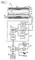
- an exemplary imaging system in the form of a magnetic resonance imaging (MRI) system 10 is illustrated diagrammatically as including a data acquisition system 12, a control system 14, and an interface system 16. Some or all of these systems include components which may store and access data for use in imaging or servicing as described more fully below. While system 10 may include any suitable scanner or detector, in the illustrated embodiment the system includes a full body scanner comprising a patient bore 18, into which a table 20 may be positioned to place a patient 22 in a desired orientation for scanning. Data acquisition system 12 may be of any suitable rating, including ratings varying from 0.2 Tesla to 1.5 Tesla, and beyond.
- Data acquisition system 12 includes a series of associated coils for producing controlled magnetic fields, and for generating radio frequency excitation pulses, and for detecting emissions from gyromagnetic material within the patient in response to such pulses.
- a primary magnet 24 is provided for generating a primary magnetic field, generally aligned with the patient bore.
- a series of gradient coils 26, 28 and 30 are grouped in a coil assembly for generating controlled magnetic gradient fields during examination sequences.
- a radio frequency coil 32 is provided for generating radio frequency pulses for exciting the gyromagnetic material. In the embodiment illustrated in Fig. 1, coil 32 also serves as a receiving coil.
- RF coil 32 may be coupled with driving and receiving circuitry in passive and active modes for receiving emissions from gyromagnetic material and for outputting radio frequency excitation pulses, respectively.
- various configurations of receiving coils may be provided separate from RF coil 32.
- Such coils may include structures specifically adapted for target anatomies, such as head coil assemblies, and so forth.
- receiving coils may be provided in any suitable physical configuration, including phased array coils, and so forth.
- gradient coils 26, 28 and 30 serve to generate precisely controlled magnetic fields, the strength of which vary over a predefined field of view, typically with positive and negative polarity.
- each coil is energized with known electric current, the resulting magnetic field gradient is superimposed over the primary field and produces a linear variation in the overall magnetic field strength across the field of view.
- Combinations of such fields, orthagonally disposed with respect to one another, enable the creation of a linear gradient in any direction by vector addition of the individual gradient fields.
- the gradient fields may be considered to be oriented both in physical planes, as well as by logical axes.
- the fields are mutually orthagonally oriented to form a coordinate system which can be rotated by appropriate manipulation of the pulsed current applied to the individual field coils.
- the coordinate system defines gradients which are typically referred to as slice select gradients, frequency encoding gradients, and phase encoding gradients.
- the slice select gradient determines a slab of tissue or anatomy to be imaged in the patient.
- the slice select gradient field may thus be applied simultaneous with a selective RF pulse to excite a known volume of spins within a desired slice that precess at the same frequency.
- the slice thickness is determined by the bandwidth of the RF pulse and the gradient strength across the field of view.
- the frequency encoding gradient axis is also known as the readout gradient axis, and is applied in a direction perpendicular to the slice select gradient.
- the frequency encoding gradient is applied before and during the formation of the MR echo signal resulting from the RF excitation.
- Spins of the gyromagnetic material under the influence of this gradient are frequency encoded according to their spatial position across the gradient field. By Fourier transformation, acquired signals may be analyzed to identify their location in the selected slice by virtue of the frequency encoding.
- phase encode gradient is generally applied in a sequence before the readout gradient and after the slice select gradient. Localization of spins in the gyromagnetic material in the phase encode direction is accomplished by sequentially inducing variations in phase of the precessing protons of the material by using slightly different gradient amplitudes that are sequentially applied during the data acquisition sequence. Phase variations are thus linearly imposed across the field of view, and spatial position within the slice is encoded by the polarity and the degree of phase difference accumulated relative to a null position.
- the phase encode gradient permits phase differences to be created among the spins of the material in accordance with their position in the phase encode direction.
- pulse sequences employing the logical axes described above.
- adaptations in the pulse sequences may be made to appropriately orient both the selected slice and the frequency and phase encoding to excite the desired material and to acquire resulting MR signals for processing.
- control system 14 thus includes a control circuit 36 for commanding the pulse sequences employed during the examinations, and for processing received signals.
- Control circuit 36 may include any suitable programmable logic device, such as a CPU or digital signal processor of a general purpose or application-specific computer.
- Control circuit 36 further includes memory circuitry 38, such as volatile and non-volatile memory devices for storing physical and logical axis configuration parameters, examination pulse sequence descriptions, acquired image data, programming routines, and so forth, used during the examination sequences implemented by the scanner.
- Interface between the control circuit 36 and the gradient coils of data acquisition system 12 is managed by amplification and driver circuitry 40.
- RF coil 32 is similarly interfaced by transmission and receive interface circuitry 42.
- Circuitry 40 includes amplifiers for each gradient field coil to supply drive current to the field coils in response to control signals from control circuit 36.
- Interface circuitry 42 includes additional power amplification circuitry for driving RF coil 32.
- circuitry 42 will typically include a switching device for toggling the RF coil between active or transmitting mode, and passive or receiving mode.
- a power supply, denoted generally by reference numeral 34 in Fig. 1, is provided for energizing the primary magnet 24.
- circuitry 14 includes interface components 44 for exchanging configuration and image data with interface system 16.
- Interface system 16 may include a wide range of devices for facilitating interface between an operator or radiologist and data acquisition system 12 via control system 14.
- an operator controller 46 is provided in the form of a computer work station employing a general purpose or application-specific computer.
- the station also typically includes memory circuitry for storing examination pulse sequence descriptions, examination protocols, user and patient data, image data, both raw and processed, and so forth.
- the station may further include various interface and peripheral drivers for receiving and exchanging data with local and remote devices.
- such devices include a conventional computer keyboard 50 and an alternative input device such as a mouse 52.
- a printer 54 is provided for generating hard copy output of documents and images reconstructed from the acquired data.
- a computer monitor 48 is provided for facilitating operator interface.
- system 10 may include various local and remote image access and examination control devices, represented generally by reference numeral 56 in Fig. 1. Such devices may include picture archiving and communication systems, teleradiology systems, and the like.
- examinations will be performed to produce image data for reconstruction of a useful image.
- these examinations include pulse sequences carried out by application of control signals to the gradient and RF coils, and by receiving resulting signals from the subject.
- these pulse sequences will be defined by both logical and physical configuration sets and parameter settings stored within control system 14.
- Fig. 2 represents, diagrammatically, relationships between functional components of control circuit 36 and configuration components stored with memory circuitry 38. The functional components facilitate coordination of the pulse sequences to accommodate preestablished settings for both logical and physical axes of the system.
- the axis control modules include a logical-to-physical module 60 which is typically implemented via software routines executed by control circuit 36.
- the conversion module is implemented through control routines which define particular pulse sequences in accordance with preestablished imaging protocols.
- code defining the conversion module references logical configuration sets 62 and physical configuration sets 64.
- the logical configuration sets may include parameters such as pulse amplitudes, beginning times, time delays, and so forth, for the various logical axes described above.
- the physical configuration sets will typically include parameters related to the physical constraints of the scanner itself, including maximum and minimum allowable currents, switching times, amplification, scaling, and so forth.
- Conversion module 60 serves to generate the pulse sequence for driving the coils of scanner 12 in accordance with constraints defined in these configuration sets.
- the conversion module will also serve to define adapted pulses for each physical axis to properly orient (e.g. rotate) slices and to encode gyromagnetic material in accordance with desired rotation or reorientations of the physical axes of the image.
- Fig. 3 illustrates a typical pulse sequence which may be implemented on a system such as that illustrated in Fig. 1 and calling upon configuration and conversion components such as those shown in Fig. 2. While many different pulse sequence definitions may be implemented, depending upon the examination type, in the example of Fig. 3, a gradient recalled acquisition in steady state mode (GRASS) pulse sequence is defined by a series of pulses and gradients appropriately timed with respect to one another.
- the pulse sequence indicated generally by reference numeral 66, is thus defined by pulses on a logical slice select axis 68, a frequency encoding axis 70, a phase encoding axis 72, an RF axis 74, and a data acquisition axis 76.
- GASS gradient recalled acquisition in steady state mode
- the pulse sequence description begins with a pair of gradient pulses on slice select axis 68 as represented at reference numeral 78.
- an RF pulse 80 is generated to excite gyromagnetic material in the subject.
- Phase encoding pulses 82 are then generated, followed by a frequency encoding gradient 84.
- a data acquisition window 86 provides for sensing signals resulting from the excitation pulses which are phase and frequency encoded.
- the pulse sequence description terminates with additional gradient pulses on the slice select, frequency encoding, and phase encoding axes.
- the foregoing operation of an MRI system, and other procedures for obtaining image data on other modality imaging systems calls for a number of peripheral devices and subsystems operating in concert.
- the pulse sequence description is typically stored within the control system 14, and carried out upon request.
- various pulse sequences may call for different peripheral devices, such as RF coils 32.
- RF coils 32 In a typical application, a clinician or radiologist will select an examination via interface system 16, and insert the appropriate RF coil in the data acquisition system 12. Similarly, the table on which the patient is positioned will be placed in the appropriate orientation, and the gradient coils will be prepared for the examination sequence.
- calibration procedures are performed on all of these peripheral devices, as well as on other components of the system.
- an identification of the peripheral devices associated with the system such as RF coil 32
- the calibration information for the coil, as well as other relevant information is, in these prior art techniques, accessed from a storage device, typically the memory circuitry 38 of the imaging system itself.
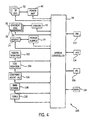
- Fig. 4 illustrates an exemplary peripheral topology 100 available through the present technique.
- a wide variety of the peripherals and subsystems of the imaging system may include circuitry for storing and accessing identification data, calibration data, and other useful information and functional code.
- each of these devices illustrated on the left of system controller 36, can receive and transmit data in digital form through system controller 36 for use in examination sequences and servicing.
- These peripherals and subsystems include the RF coils 32 and power amplification circuitry 42 for driving the coils. Each individual coil may include circuitry for storage of the data, as may the power amplification circuitry.
- peripheral devices and subsystems may include gradient coils 26, 28 and 30, as well as driver circuitry 40 for controlling the fields produced by the gradient coils.
- Magnet 24, as well as its power supply 34 may be similarly equipped.
- similar peripheral devices may further include respiration monitors 102, ECG monitors 104, and contrast agent injection devices 106.
- stimulating devices for functional MRI (fMRI) examinations may be equipped for storing and accessing data, as indicated at reference numeral 108.
- additional components of the system such as table 20 may be equipped with circuitry, as indicated at reference numeral 110 in Fig. 4, for providing similar information.
- the information which may be stored and accessed in the various peripheral devices may vary widely depending upon the nature of the peripheral device and its use in the system. For example, in the case of gradient coils and RF coils of an MRI system, data may be stored in each device to provide an indication of the peripheral type, its identification, the manufacturing date and source, and field strength. Calibration information resulting from separate calibration sequences may also be stored in the devices. Finally, service histories, including references or code indicative of particular services performed on the devices or problems encountered in the devices in the past may be similarly stored directly on the device. Other devices may have unique information associated with them which may be similarly stored.
- the circuitry 110 associated with the table for positioning a patient in an MRI system may include data indicative of weight limitations of the table which are accessed and used by the system during examinations.
- the information may serve as a basis, for example, in notifications or alarms output to clinicians when weight limits are approached or exceeded.
- each peripheral device or subsystem may further include executable code which may be carried out in coordination with system controller 36, or other external circuitry.
- executable code may be stored in peripheral devices requiring such calibration for examination sequences.
- These programs may be self executing upon connection of the devices to the system, as described below, or may be accessed and executed upon an operator prompt or upon a call sequence from a routine executed by the external components.
- system controller 36 may store information on each device, and access the information as desired for particular imaging needs.
- system controller 36 may act as an interface for conveying certain of the information to other systems, both within an institution and outside the institution.
- a radiology department informational system 112 may be coupled to system controller, such as via an intranet or the like, to access information from the peripheral devices and subsystems, and to download information to each device as desired. Similar information exchange may be performed with a hospital information system, as indicated at reference numeral 114.
- a field engineer station 116 may similarly communicate with the peripheral devices and subsystems through system controller 36.
- a field engineer laptop may be coupled to a system controller for accessing service records, calibration information, usage information, and so forth, from each device.
- a remote servicing facility 118 may communicate with system controller to access the data from the peripheral devices and subsystems.
- the service facility accessing in this manner may be entirely remote from the imaging system or institution, such as in a remote service center connected to the institution via an open wide area network, such as the Internet, a virtual proprietary network or the like.
- FIG. 5 illustrates an exemplary peripheral topology 120 in accordance with a present embodiment.
- a processing circuit 122 is provided for executing any functional code, exchanging data, responding to data requests, and so forth.
- Processing circuit 122 which may typically include a programmed microprocessor, draws data from a memory circuit 124 where the data is stored.
- the memory circuit may include any suitable type of memory, but preferably includes non-volatile memory capable of retaining the data when power is removed from the peripheral device or subsystem.
- Processing circuit 122 may also write data to the memory circuit, such as upon initial manufacturing and testing of the device, following calibration sequences, following service events, and so forth.
- the peripheral device or subsystem includes sensors 128, these also form part of the preferred topology.
- sensors may be provided, for example, for detecting temperatures of coils, acoustical signals for cardiac monitors, flow rates for contrast agent injection devices, force or a related parameter for table weight monitoring, and so forth.
- interface circuitry 130 is provided for conditioning signals received from the sensors 128 before application of the signals to processing circuitry 122. It should be noted that in addition to the exchange of data in the topology of Fig. 5, power may also be transmitted between the devices such as for powering processing circuit 122 and sensors 128.
- interface circuitry 126 may be provided in each device for encrypting and decrypting stored data. As will be appreciated by those skilled in the art, such circuitry will generally translate data stored and processed within the device to an encrypted or decrypted form so as to limit access or the utility of the data to external circuits. Interface 126 may further include circuitry for verification of the identity of a requesting circuit as described below. Such identification is particularly useful in limiting access of the stored data by external circuitry, devices, and personnel.
- the topology provided in the embodiment of Fig. 5 may be based upon any suitable programming code and architecture.
- a product family available from Dallas Semiconductor of Dallas, Texas, under the commercial designation Crypto iButton serves as the platform for the topology.
- Such devices were installed in a quick disconnect box for a variety of RF coils of an MRI system.
- the devices were then programmed to contain manufacturing and calibration data specific to each coil, as well as a dynamically updated record of the total number of uses of the coil.
- the coil was automatically identified by the imaging system interface and the interface was updated to reflect insertion of the coil, including an electronic image of the coil itself, provided on a monitor (see monitor 48 in Fig. 1).
- the system was made back-compatible for coils not equipped with the preferred data topology by prompting the user to select a coil from a list of candidate coils when the coil was not identified during the initial connection sequence.
- the device included a single-chip trusted microcomputer as processing circuit 122, equipped with a Java virtual machine, a 1024-bit math accelerator, and an unalterable real time clock.
- Memory circuit 124 included a 6 Kbyte random access memory and a 32 Kbyte read-only memory.
- the processing functions included RSA encryption.
- More limited topographies are, of course, available in the present technique. For example, where no processing capabilities are required, or very limited capabilities are required, specific analog or digital circuitry may be provided in the topology for this purpose. Moreover, memory-only devices may be provided in which data is merely stored and accessed.
- Fig. 6 illustrates exemplary control logic, designated generally by reference numeral 132, for data management through a device equipped as illustrated in Fig. 5 in accordance with the present technique.
- the device is first connected to other system components, as indicated at step 134.
- separable peripheral devices or subsystems may be physically connected at this step, or resident peripheral devices and subsystems may be connected during installation.
Landscapes
- Health & Medical Sciences (AREA)
- Engineering & Computer Science (AREA)
- Life Sciences & Earth Sciences (AREA)
- Medical Informatics (AREA)
- Physics & Mathematics (AREA)
- Nuclear Medicine, Radiotherapy & Molecular Imaging (AREA)
- Biomedical Technology (AREA)
- General Health & Medical Sciences (AREA)
- Public Health (AREA)
- Radiology & Medical Imaging (AREA)
- High Energy & Nuclear Physics (AREA)
- Animal Behavior & Ethology (AREA)
- Primary Health Care (AREA)
- Veterinary Medicine (AREA)
- Pathology (AREA)
- Epidemiology (AREA)
- Heart & Thoracic Surgery (AREA)
- Molecular Biology (AREA)
- Surgery (AREA)
- Biophysics (AREA)
- Optics & Photonics (AREA)
- Business, Economics & Management (AREA)
- General Business, Economics & Management (AREA)
- Condensed Matter Physics & Semiconductors (AREA)
- General Physics & Mathematics (AREA)
- Magnetic Resonance Imaging Apparatus (AREA)
- Measuring And Recording Apparatus For Diagnosis (AREA)
Applications Claiming Priority (2)
| Application Number | Priority Date | Filing Date | Title |
|---|---|---|---|
| US09/469,999 US6356780B1 (en) | 1999-12-22 | 1999-12-22 | Method and apparatus for managing peripheral devices in a medical imaging system |
| US469999 | 1999-12-22 |
Publications (3)
| Publication Number | Publication Date |
|---|---|
| EP1110504A2 EP1110504A2 (en) | 2001-06-27 |
| EP1110504A3 EP1110504A3 (en) | 2003-04-02 |
| EP1110504B1 true EP1110504B1 (en) | 2006-02-15 |
Family
ID=23865889
Family Applications (1)
| Application Number | Title | Priority Date | Filing Date |
|---|---|---|---|
| EP00311532A Expired - Lifetime EP1110504B1 (en) | 1999-12-22 | 2000-12-21 | Method and apparatus for managing peripheral devices in a medical imaging system |
Country Status (4)
| Country | Link |
|---|---|
| US (1) | US6356780B1 (enExample) |
| EP (1) | EP1110504B1 (enExample) |
| JP (1) | JP2001245868A (enExample) |
| DE (1) | DE60026003T2 (enExample) |
Families Citing this family (93)
| Publication number | Priority date | Publication date | Assignee | Title |
|---|---|---|---|---|
| US6050943A (en) | 1997-10-14 | 2000-04-18 | Guided Therapy Systems, Inc. | Imaging, therapy, and temperature monitoring ultrasonic system |
| US6249120B1 (en) * | 1998-07-22 | 2001-06-19 | General Electric Company | Modular timemasking sequence programming for imaging system |
| US6674449B1 (en) * | 1998-11-25 | 2004-01-06 | Ge Medical Systems Global Technology Company, Llc | Multiple modality interface for imaging systems |
| US6440071B1 (en) * | 1999-10-18 | 2002-08-27 | Guided Therapy Systems, Inc. | Peripheral ultrasound imaging system |
| US6418334B1 (en) * | 1999-10-19 | 2002-07-09 | General Electric Company | Method and apparatus for logging and dynamically configuring performance analysis of a medical diagnostic imaging system |
| US7383358B1 (en) * | 1999-12-29 | 2008-06-03 | Ge Medical Technology Services, Inc. | System and method for remote servicing of in-field product |
| EP1229472A4 (en) * | 2000-03-14 | 2004-12-15 | Toshiba Kk | MRI SYSTEMS CENTER AND MRI SYSTEM |
| US6656119B2 (en) * | 2000-03-17 | 2003-12-02 | Kabushiki Kaisha Toshiba | Imaging diagnostic apparatus and maintenance method of the same |
| US6946836B2 (en) * | 2000-04-25 | 2005-09-20 | Kabushiki Kaisha Toshiba | Magnetic resonance imaging involving movement of patient's couch |
| JP3864035B2 (ja) * | 2000-05-19 | 2006-12-27 | オリンパス株式会社 | 内視鏡システム |
| US7914453B2 (en) | 2000-12-28 | 2011-03-29 | Ardent Sound, Inc. | Visual imaging system for ultrasonic probe |
| US20020143857A1 (en) * | 2001-03-30 | 2002-10-03 | Bidarahalli Phani Kumar | Method and system for event communication on a distributed scanner/workstation platform |
| JP4369074B2 (ja) * | 2001-05-11 | 2009-11-18 | ジーイー・メディカル・システムズ・グローバル・テクノロジー・カンパニー・エルエルシー | 高速ad変換信号処理装置、デジタルレシーバフロントエンド回路およびmri装置 |
| DE60239812D1 (de) | 2001-08-08 | 2011-06-01 | Stryker Corp | Chirurgisches werkzeugsystem mit komponenten, die einen induktiven datentransfer durchführen |
| DE10146210B4 (de) * | 2001-09-19 | 2008-03-27 | Siemens Ag | Verfahren zum Justieren eines medizintechnischen Gerätes und medizintechnisches Gerät |
| JP2004021576A (ja) * | 2002-06-17 | 2004-01-22 | Fuji Xerox Co Ltd | 画像形成システム、画像形成システムにおけるダウンロード方法 |
| US7887559B2 (en) | 2002-08-08 | 2011-02-15 | Stryker Corporation | Surgical cutting accessory with encapsulated RFID chip |
| US7237990B2 (en) | 2002-08-08 | 2007-07-03 | Stryker Corporation | Surgical tool system with quick release coupling assembly |
| US7310498B2 (en) * | 2003-04-09 | 2007-12-18 | Standard Microsystems Corporation | Communication protocol for personal computer system human interface devices over a low bandwidth, bi-directional radio frequency link |
| US20040203480A1 (en) * | 2003-04-09 | 2004-10-14 | Dutton Drew J. | Configuration and management of human interface and other attached devices through bi-directional radio frequency link |
| WO2005017548A1 (en) * | 2003-08-15 | 2005-02-24 | Koninklijke Philips Electronics N.V. | Mri system with wireless identification capability |
| US7346203B2 (en) * | 2003-11-19 | 2008-03-18 | General Electric Company | Methods and apparatus for processing image data to aid in detecting disease |
| US7218106B2 (en) * | 2003-12-04 | 2007-05-15 | Kabushiki Kaisha Toshiba | MRI with automatic contour-controlled separation between RF coil and object being imaged |
| DE102004017185B4 (de) * | 2004-04-07 | 2010-06-10 | Siemens Ag | Medizinisches Gesamtsystem |
| JP4718793B2 (ja) * | 2004-04-23 | 2011-07-06 | 株式会社東芝 | Mri装置 |
| US8235909B2 (en) | 2004-05-12 | 2012-08-07 | Guided Therapy Systems, L.L.C. | Method and system for controlled scanning, imaging and/or therapy |
| US7927313B2 (en) * | 2004-05-27 | 2011-04-19 | Baxter International Inc. | Medical device configuration based on recognition of identification information |
| US20050277873A1 (en) * | 2004-05-27 | 2005-12-15 | Janice Stewart | Identification information recognition system for a medical device |
| US8961461B2 (en) * | 2004-05-27 | 2015-02-24 | Baxter International Inc. | Multi-state alarm system for a medical pump |
| US7393325B2 (en) | 2004-09-16 | 2008-07-01 | Guided Therapy Systems, L.L.C. | Method and system for ultrasound treatment with a multi-directional transducer |
| US9011336B2 (en) | 2004-09-16 | 2015-04-21 | Guided Therapy Systems, Llc | Method and system for combined energy therapy profile |
| US7824348B2 (en) | 2004-09-16 | 2010-11-02 | Guided Therapy Systems, L.L.C. | System and method for variable depth ultrasound treatment |
| US20120165848A1 (en) | 2010-08-02 | 2012-06-28 | Guided Therapy Systems, Llc | System and method for treating cartilage |
| US8535228B2 (en) | 2004-10-06 | 2013-09-17 | Guided Therapy Systems, Llc | Method and system for noninvasive face lifts and deep tissue tightening |
| US8444562B2 (en) | 2004-10-06 | 2013-05-21 | Guided Therapy Systems, Llc | System and method for treating muscle, tendon, ligament and cartilage tissue |
| US10864385B2 (en) | 2004-09-24 | 2020-12-15 | Guided Therapy Systems, Llc | Rejuvenating skin by heating tissue for cosmetic treatment of the face and body |
| EP1879502A2 (en) | 2004-10-06 | 2008-01-23 | Guided Therapy Systems, L.L.C. | Method and system for cosmetic enhancement |
| US8133180B2 (en) | 2004-10-06 | 2012-03-13 | Guided Therapy Systems, L.L.C. | Method and system for treating cellulite |
| US11235179B2 (en) | 2004-10-06 | 2022-02-01 | Guided Therapy Systems, Llc | Energy based skin gland treatment |
| US9827449B2 (en) | 2004-10-06 | 2017-11-28 | Guided Therapy Systems, L.L.C. | Systems for treating skin laxity |
| US11883688B2 (en) | 2004-10-06 | 2024-01-30 | Guided Therapy Systems, Llc | Energy based fat reduction |
| US9694212B2 (en) | 2004-10-06 | 2017-07-04 | Guided Therapy Systems, Llc | Method and system for ultrasound treatment of skin |
| US7758524B2 (en) | 2004-10-06 | 2010-07-20 | Guided Therapy Systems, L.L.C. | Method and system for ultra-high frequency ultrasound treatment |
| US20060111744A1 (en) | 2004-10-13 | 2006-05-25 | Guided Therapy Systems, L.L.C. | Method and system for treatment of sweat glands |
| EP2409728B1 (en) | 2004-10-06 | 2017-09-27 | Guided Therapy Systems, L.L.C. | System for ultrasound tissue treatment |
| US8690778B2 (en) | 2004-10-06 | 2014-04-08 | Guided Therapy Systems, Llc | Energy-based tissue tightening |
| US11207548B2 (en) | 2004-10-07 | 2021-12-28 | Guided Therapy Systems, L.L.C. | Ultrasound probe for treating skin laxity |
| US11724133B2 (en) | 2004-10-07 | 2023-08-15 | Guided Therapy Systems, Llc | Ultrasound probe for treatment of skin |
| US20080004507A1 (en) * | 2004-10-27 | 2008-01-03 | E-Z-Em, Inc. | Data collection device, system, method, and computer program product for collecting data related to the dispensing of contrast media |
| EP1805683B1 (en) * | 2004-10-27 | 2019-01-23 | ACIST Medical Systems, Inc. | Data collection device, system, method, and computer program product for collecting data related to the dispensing of contrast media |
| US20060168338A1 (en) * | 2004-11-23 | 2006-07-27 | Bruegl Aaron R | Methods and systems for providing data across a network |
| DE602005021249D1 (de) * | 2004-12-09 | 2010-06-24 | Stryker Corp | Drahtloses system zur bereitstellung von instrumenten- und implantatdaten an ein chirurgisches navigationsgerät |
| WO2006116480A2 (en) | 2005-04-25 | 2006-11-02 | Guided Therapy Systems, L.L.C. | Method and system for enhancing computer peripheral saftey |
| US20070016686A1 (en) * | 2005-07-13 | 2007-01-18 | Hollebeek Robert J | Retrieval system and retrieval method for retrieving medical images |
| US20080005262A1 (en) * | 2006-06-16 | 2008-01-03 | Henry Wurzburg | Peripheral Sharing USB Hub for a Wireless Host |
| US9566454B2 (en) | 2006-09-18 | 2017-02-14 | Guided Therapy Systems, Llc | Method and sysem for non-ablative acne treatment and prevention |
| US9241683B2 (en) * | 2006-10-04 | 2016-01-26 | Ardent Sound Inc. | Ultrasound system and method for imaging and/or measuring displacement of moving tissue and fluid |
| US9216276B2 (en) | 2007-05-07 | 2015-12-22 | Guided Therapy Systems, Llc | Methods and systems for modulating medicants using acoustic energy |
| EP2152167B1 (en) | 2007-05-07 | 2018-09-05 | Guided Therapy Systems, L.L.C. | Methods and systems for coupling and focusing acoustic energy using a coupler member |
| US20150174388A1 (en) | 2007-05-07 | 2015-06-25 | Guided Therapy Systems, Llc | Methods and Systems for Ultrasound Assisted Delivery of a Medicant to Tissue |
| CN101688906B (zh) * | 2007-06-19 | 2013-07-17 | 皇家飞利浦电子股份有限公司 | 核磁共振成像射频接收器 |
| RU2511641C2 (ru) * | 2008-06-04 | 2014-04-10 | Конинклейке Филипс Электроникс Н.В. | Адаптивное управление скоростью передачи данных |
| HRP20160499T1 (hr) | 2008-06-06 | 2016-07-15 | Ulthera, Inc. | Sustav za kozmetički tretman i snimanje |
| US12102473B2 (en) | 2008-06-06 | 2024-10-01 | Ulthera, Inc. | Systems for ultrasound treatment |
| US7833829B2 (en) * | 2008-10-28 | 2010-11-16 | Honeywell International Inc. | MEMS devices and methods of assembling micro electromechanical systems (MEMS) |
| KR20110101204A (ko) | 2008-12-24 | 2011-09-15 | 가이디드 테라피 시스템스, 엘.엘.씨. | 지방 감소 및/또는 셀룰라이트 치료 방법 및 시스템 |
| US8715186B2 (en) | 2009-11-24 | 2014-05-06 | Guided Therapy Systems, Llc | Methods and systems for generating thermal bubbles for improved ultrasound imaging and therapy |
| US9504446B2 (en) | 2010-08-02 | 2016-11-29 | Guided Therapy Systems, Llc | Systems and methods for coupling an ultrasound source to tissue |
| US8857438B2 (en) | 2010-11-08 | 2014-10-14 | Ulthera, Inc. | Devices and methods for acoustic shielding |
| BR112013028677A8 (pt) | 2011-05-09 | 2018-02-06 | Liebel Flarsheim Co Llc | Sistema injetor de meio de contraste e sistema médico compreendendo o sistema injetor de meio de contraste |
| WO2013009785A2 (en) | 2011-07-10 | 2013-01-17 | Guided Therapy Systems, Llc. | Systems and methods for improving an outside appearance of skin using ultrasound as an energy source |
| EP2731675B1 (en) | 2011-07-11 | 2023-05-03 | Guided Therapy Systems, L.L.C. | Systems and methods for coupling an ultrasound source to tissue |
| US9263663B2 (en) | 2012-04-13 | 2016-02-16 | Ardent Sound, Inc. | Method of making thick film transducer arrays |
| US10157263B2 (en) | 2012-05-08 | 2018-12-18 | Liebel-Flarsheim Company Llc | Contrast media injection data management |
| US9510802B2 (en) | 2012-09-21 | 2016-12-06 | Guided Therapy Systems, Llc | Reflective ultrasound technology for dermatological treatments |
| CN204017181U (zh) | 2013-03-08 | 2014-12-17 | 奥赛拉公司 | 美学成像与处理系统、多焦点处理系统和执行美容过程的系统 |
| WO2014146022A2 (en) | 2013-03-15 | 2014-09-18 | Guided Therapy Systems Llc | Ultrasound treatment device and methods of use |
| EP3090274A1 (en) * | 2014-01-03 | 2016-11-09 | Koninklijke Philips N.V. | Calculation of the probability of gradient coil amplifier failure using environment data |
| ES2972602T3 (es) | 2014-04-18 | 2024-06-13 | Ulthera Inc | Terapia de ultrasonido con transductor de banda |
| DE102014211686B4 (de) * | 2014-06-18 | 2018-09-27 | Siemens Healthcare Gmbh | Verfahren zum Betrieb einer Magnetresonanzanlage und Magnetresonanzanlage hierfür |
| JP6967001B2 (ja) | 2016-01-18 | 2021-11-17 | ウルセラ インコーポレイテッド | フレキシブルなプリント回路基板の周囲に電気的接続している環状超音波アレイを有するコンパクトな超音波デバイス、および、その組立方法 |
| DK3981466T3 (da) | 2016-08-16 | 2023-10-09 | Ulthera Inc | Systemer og fremgangsmåder til kosmetisk ultralydsbehandling af hud |
| CN110431802B (zh) | 2017-01-13 | 2023-06-16 | 皇家飞利浦有限公司 | 用于mri线圈的基于混沌编码的通信 |
| TW202529848A (zh) | 2018-01-26 | 2025-08-01 | 美商奧賽拉公司 | 用於多個維度中的同時多聚焦超音治療的系統和方法 |
| US11944849B2 (en) | 2018-02-20 | 2024-04-02 | Ulthera, Inc. | Systems and methods for combined cosmetic treatment of cellulite with ultrasound |
| US11248939B2 (en) | 2018-09-12 | 2022-02-15 | Keysight Technologies, Inc. | Methods, systems, and computer readable media for calibration testing and traceability using a distributed ledger |
| US10797873B2 (en) | 2018-09-12 | 2020-10-06 | Keysight Technologies, Inc. | Methods, systems, and computer readable media for verifying calibration information using a distributed ledger |
| EP3664097A1 (en) * | 2018-12-04 | 2020-06-10 | Siemens Healthcare GmbH | Attaching peripheral components of a medical imaging system |
| US12377293B2 (en) | 2019-07-15 | 2025-08-05 | Ulthera, Inc. | Systems and methods for measuring elasticity with imaging of ultrasound multi-focus shearwaves in multiple dimensions |
| US20240120083A1 (en) * | 2021-02-17 | 2024-04-11 | C. R. Bard, Inc. | Capital Equipment Auto-Enabled Features |
| EP4299002A1 (de) * | 2022-06-29 | 2024-01-03 | Siemens Healthcare GmbH | Vorrichtung und verfahren zur sicheren kommunikation zwischen einem peripheriegerät und einem medizingerät |
| EP4474846A1 (en) * | 2023-06-07 | 2024-12-11 | Koninklijke Philips N.V. | Interface for a magnetic resonance imaging system |
| EP4589601A1 (en) * | 2024-01-17 | 2025-07-23 | Koninklijke Philips N.V. | Method, device and system for managing a plurality of medical devices |
Family Cites Families (20)
| Publication number | Priority date | Publication date | Assignee | Title |
|---|---|---|---|---|
| US4712560A (en) * | 1985-08-09 | 1987-12-15 | General Electric Company | Apparatus and method of acquiring physiological gating signals for magnetic resonance imaging of moving objects |
| JPS62165307A (ja) * | 1986-01-16 | 1987-07-21 | Fuji Electric Co Ltd | 液冷式均一磁場コイル |
| JPH02174833A (ja) * | 1988-09-27 | 1990-07-06 | Fuji Electric Co Ltd | 磁気共鳴ct装置 |
| JPH02257938A (ja) * | 1989-03-31 | 1990-10-18 | Hitachi Medical Corp | Mri装置 |
| EP0565738A1 (en) * | 1990-01-05 | 1993-10-20 | Symbol Technologies, Inc. | System for encoding and decoding data in machine readable graphic form |
| US5216367A (en) * | 1990-02-21 | 1993-06-01 | Kabushiki Kaisha Toshiba | MR imaging apparatus capable of automatically selecting multiple surface coils |
| JPH04102443A (ja) * | 1990-08-23 | 1992-04-03 | Toshiba Corp | 磁気共鳴イメージング装置 |
| JP3292305B2 (ja) * | 1991-09-12 | 2002-06-17 | 株式会社日立メディコ | 磁気共鳴イメージング装置 |
| DE4143092A1 (de) * | 1991-12-27 | 1993-07-01 | Bayer Ag | Gasspurenmesssystem |
| JP2541081B2 (ja) * | 1992-08-28 | 1996-10-09 | 日本電気株式会社 | バイオセンサ及びバイオセンサの製造・使用方法 |
| US5311135A (en) * | 1992-12-11 | 1994-05-10 | General Electric Company | Multiple tap gradient field coil for magnetic resonance imaging |
| US6206829B1 (en) * | 1996-07-12 | 2001-03-27 | First Opinion Corporation | Computerized medical diagnostic and treatment advice system including network access |
| US5551430A (en) | 1994-08-05 | 1996-09-03 | Picker International, Inc. | RF coil identification and testing interface for NMR systems |
| US5781442A (en) * | 1995-05-15 | 1998-07-14 | Alaris Medical Systems, Inc. | System and method for collecting data and managing patient care |
| DE19549211C1 (de) * | 1995-12-30 | 1997-05-15 | Bruker Analytische Messtechnik | Magnetsystem |
| US5782805A (en) * | 1996-04-10 | 1998-07-21 | Meinzer; Randolph | Medical infusion pump |
| US5853005A (en) * | 1996-05-02 | 1998-12-29 | The United States Of America As Represented By The Secretary Of The Army | Acoustic monitoring system |
| DE19629646C2 (de) * | 1996-07-23 | 1998-09-10 | Wolf Gmbh Richard | Verfahren und Vorrichtung zur automatischen Identifikation von Komponenten medizinischer Gerätesysteme |
| US6389156B1 (en) * | 1997-10-09 | 2002-05-14 | Konica Corporation | Method and apparatus for reading radiographic images |
| JP3597035B2 (ja) * | 1998-01-30 | 2004-12-02 | 日本電子株式会社 | オートチューニングプローブ |
-
1999
- 1999-12-22 US US09/469,999 patent/US6356780B1/en not_active Expired - Lifetime
-
2000
- 2000-12-21 JP JP2000388010A patent/JP2001245868A/ja active Pending
- 2000-12-21 DE DE60026003T patent/DE60026003T2/de not_active Expired - Lifetime
- 2000-12-21 EP EP00311532A patent/EP1110504B1/en not_active Expired - Lifetime
Also Published As
| Publication number | Publication date |
|---|---|
| DE60026003T2 (de) | 2006-09-28 |
| US6356780B1 (en) | 2002-03-12 |
| JP2001245868A (ja) | 2001-09-11 |
| DE60026003D1 (de) | 2006-04-20 |
| EP1110504A2 (en) | 2001-06-27 |
| EP1110504A3 (en) | 2003-04-02 |
Similar Documents
| Publication | Publication Date | Title |
|---|---|---|
| EP1110504B1 (en) | Method and apparatus for managing peripheral devices in a medical imaging system | |
| US20030214953A1 (en) | Networked magnetic resonance imaging system and method incorporating same | |
| US6492812B1 (en) | MR imaging system with interactive MR geometry prescription control over a network | |
| EP2652653B1 (en) | Magnetic resonance examination system with preferred settings based on data mining | |
| US6591127B1 (en) | Integrated multi-modality imaging system and method | |
| US20060293588A1 (en) | Method and medical imaging apparatus for planning an image acquisition based on a previously-generated reference image | |
| JP2005125099A (ja) | 断層撮影イメージングシステム用の標準測定プロトコルの作成方法、コンピュータプログラム製品および断層撮影イメージングシステム内に実際対象物の撮像範囲を位置決めする計画方法 | |
| US10241175B2 (en) | Medical imaging apparatus having multiple subsystems, and operating method therefor | |
| US10168407B2 (en) | Medical imaging apparatus having multiple subsystems, and operating method therefor | |
| CN102657529A (zh) | 用于传送数据的系统和方法 | |
| US20130141092A1 (en) | Method of optimizing magnetic resonance scanning parameters | |
| US20140195954A1 (en) | Accessories as Workflow Priors in Medical Systems | |
| US11821970B2 (en) | Gradient coil apparatus and methods for MRI | |
| JP3980897B2 (ja) | 磁気共鳴映像装置、磁気共鳴映像装置の種々のパラメータ設定に関する情報提供方法、及び当該情報提供システム | |
| JP5063610B2 (ja) | 医用画像診断装置及びリモートメンテナンスシステム | |
| US6586935B1 (en) | Magnetic resonance image artifact correction using navigator echo information | |
| JP2012503517A (ja) | 画像診断システム及び方法 | |
| US20230070444A1 (en) | Method and System for Image-Based Operational Decision Support | |
| WO2021030466A1 (en) | Simultaneous multi-orientation magnetic resonance imaging | |
| US20080161784A1 (en) | Method and system for remotely controlled MR-guided focused ultrasound ablation | |
| CN119920433A (zh) | 用于磁共振条件性植入物数据配置和存储的系统和方法 | |
| US20160367142A1 (en) | Medical imaging apparatus in a medical imaging system, and system control computer for operation thereof during a medical imaging examination | |
| US12111370B2 (en) | System and method for active monitoring and mitigation of thermal events on magnetic resonance coils | |
| US20250098980A1 (en) | Magnetic resonance scanning system and method | |
| CN114661308A (zh) | 用于在磁共振设备上执行至少一个应用程序的方法 |
Legal Events
| Date | Code | Title | Description |
|---|---|---|---|
| PUAI | Public reference made under article 153(3) epc to a published international application that has entered the european phase |
Free format text: ORIGINAL CODE: 0009012 |
|
| AK | Designated contracting states |
Kind code of ref document: A2 Designated state(s): AT BE CH CY DE DK ES FI FR GB GR IE IT LI LU MC NL PT SE TR |
|
| AX | Request for extension of the european patent |
Free format text: AL;LT;LV;MK;RO;SI |
|
| PUAL | Search report despatched |
Free format text: ORIGINAL CODE: 0009013 |
|
| AK | Designated contracting states |
Kind code of ref document: A3 Designated state(s): AT BE CH CY DE DK ES FI FR GB GR IE IT LI LU MC NL PT SE TR |
|
| AX | Request for extension of the european patent |
Extension state: AL LT LV MK RO SI |
|
| 17P | Request for examination filed |
Effective date: 20031002 |
|
| AKX | Designation fees paid |
Designated state(s): DE NL |
|
| 17Q | First examination report despatched |
Effective date: 20040819 |
|
| GRAP | Despatch of communication of intention to grant a patent |
Free format text: ORIGINAL CODE: EPIDOSNIGR1 |
|
| GRAS | Grant fee paid |
Free format text: ORIGINAL CODE: EPIDOSNIGR3 |
|
| GRAA | (expected) grant |
Free format text: ORIGINAL CODE: 0009210 |
|
| AK | Designated contracting states |
Kind code of ref document: B1 Designated state(s): DE NL |
|
| REF | Corresponds to: |
Ref document number: 60026003 Country of ref document: DE Date of ref document: 20060420 Kind code of ref document: P |
|
| PLBE | No opposition filed within time limit |
Free format text: ORIGINAL CODE: 0009261 |
|
| STAA | Information on the status of an ep patent application or granted ep patent |
Free format text: STATUS: NO OPPOSITION FILED WITHIN TIME LIMIT |
|
| 26N | No opposition filed |
Effective date: 20061116 |
|
| PGFP | Annual fee paid to national office [announced via postgrant information from national office to epo] |
Ref country code: NL Payment date: 20151226 Year of fee payment: 16 |
|
| PGFP | Annual fee paid to national office [announced via postgrant information from national office to epo] |
Ref country code: DE Payment date: 20151229 Year of fee payment: 16 |
|
| REG | Reference to a national code |
Ref country code: DE Ref legal event code: R119 Ref document number: 60026003 Country of ref document: DE |
|
| REG | Reference to a national code |
Ref country code: NL Ref legal event code: MM Effective date: 20170101 |
|
| PG25 | Lapsed in a contracting state [announced via postgrant information from national office to epo] |
Ref country code: NL Free format text: LAPSE BECAUSE OF NON-PAYMENT OF DUE FEES Effective date: 20170101 |
|
| PG25 | Lapsed in a contracting state [announced via postgrant information from national office to epo] |
Ref country code: DE Free format text: LAPSE BECAUSE OF NON-PAYMENT OF DUE FEES Effective date: 20170701 |