EP1108894A2 - Centrifugal pump for viscous materials - Google Patents
Centrifugal pump for viscous materials Download PDFInfo
- Publication number
- EP1108894A2 EP1108894A2 EP00126934A EP00126934A EP1108894A2 EP 1108894 A2 EP1108894 A2 EP 1108894A2 EP 00126934 A EP00126934 A EP 00126934A EP 00126934 A EP00126934 A EP 00126934A EP 1108894 A2 EP1108894 A2 EP 1108894A2
- Authority
- EP
- European Patent Office
- Prior art keywords
- pump
- holder
- housing
- cutting
- pump according
- Prior art date
- Legal status (The legal status is an assumption and is not a legal conclusion. Google has not performed a legal analysis and makes no representation as to the accuracy of the status listed.)
- Granted
Links
Images

Classifications
-
- F—MECHANICAL ENGINEERING; LIGHTING; HEATING; WEAPONS; BLASTING
- F04—POSITIVE - DISPLACEMENT MACHINES FOR LIQUIDS; PUMPS FOR LIQUIDS OR ELASTIC FLUIDS
- F04D—NON-POSITIVE-DISPLACEMENT PUMPS
- F04D29/00—Details, component parts, or accessories
- F04D29/40—Casings; Connections of working fluid
- F04D29/42—Casings; Connections of working fluid for radial or helico-centrifugal pumps
- F04D29/426—Casings; Connections of working fluid for radial or helico-centrifugal pumps especially adapted for liquid pumps
-
- F—MECHANICAL ENGINEERING; LIGHTING; HEATING; WEAPONS; BLASTING
- F04—POSITIVE - DISPLACEMENT MACHINES FOR LIQUIDS; PUMPS FOR LIQUIDS OR ELASTIC FLUIDS
- F04D—NON-POSITIVE-DISPLACEMENT PUMPS
- F04D13/00—Pumping installations or systems
- F04D13/02—Units comprising pumps and their driving means
- F04D13/021—Units comprising pumps and their driving means containing a coupling
-
- F—MECHANICAL ENGINEERING; LIGHTING; HEATING; WEAPONS; BLASTING
- F04—POSITIVE - DISPLACEMENT MACHINES FOR LIQUIDS; PUMPS FOR LIQUIDS OR ELASTIC FLUIDS
- F04D—NON-POSITIVE-DISPLACEMENT PUMPS
- F04D13/00—Pumping installations or systems
- F04D13/02—Units comprising pumps and their driving means
- F04D13/06—Units comprising pumps and their driving means the pump being electrically driven
- F04D13/08—Units comprising pumps and their driving means the pump being electrically driven for submerged use
Definitions
- the invention relates to a pump, in particular a Centrifugal pump for thick matter, with a drive linkage, at the lower end of a housing with the pump a holder arranged at a distance from the drive linkage is, with the housing facing upwards Has enema.
- Such pumps are used in particular as slurry pumps used and in containers with pumpable, viscous substances lowered.
- the pump is on up lowered the bottom of the container.
- Inlet directed above is achieved that the on the Foreign objects located on the floor, such as Stones, not immediately sucked in.
- the invention is therefore based on the object To further develop the pump of the type mentioned at the beginning, that the suction of the pump is increased and a Clogging by foreign substances is effectively prevented.
- a pump especially a centrifugal pump for thick matter, with a Drive linkage, at its lower end Pump housing, or the actual pump, with a Holder is arranged at a distance from the drive linkage, the housing having an upward inlet has, the holder according to the invention straight line between the attachment points of the Holder on the drive linkage and the housing with a formed outward shape.
- This will reached a cross-sectional expansion, so that a particularly large inlet for the liquid to be pumped is ready.
- the holder is preferably essentially composed of two Striving formed. These connect the pump to the Drive linkage, so that between the struts only the drive shaft that extends inside the Drive linkage is arranged and in the pump Impeller drives. Basically, it is also possible to have three or more struts, but this will make the restricted space between the struts and the free cross section reduced. Basically, it is cheap to use as few struts as possible. Also the use of a single strut is conceivable.
- the holder preferably detects an arc exterior shape. Basically, they are also angular Forms conceivable, but it is preferred to use the holder to form an arc, as a result of which a higher Stability and easier editing possible becomes.
- the holder is particularly in the upper area domed on the outside and then extends essentially straight to the lower attachment point on the pump.
- the The holder is approximately crown-shaped in outline. Other shapes are also possible, such as one Form each strut of the holder as a semicircle.
- the holder is at least as wide trained as the pump. This will make a big one Cross section of the holder ensured. In particular is it is preferred to design the holder so that it fits into its largest external dimensions up to the pump housing extends beyond.
- the pump preferably has a spiral housing with a impeller arranged therein, so that an inlet of is given above and on the side the outlet from the pump takes place and from there, for example, via a hose is pumped up.
- the cutting propeller is preferably the same Drive shaft driven like one in the pump arranged impeller. This is the structure of the pump overall particularly easy. Furthermore, it is preferred design the cutting propeller to have two blades. Other propeller designs are also fundamentally possible, but it has been shown that a double wing Cutting propeller particularly good results in terms of the cutting effect.
- the inner surface adjacent to a peripheral edge of the cutting propeller is. This will ensure that Cutting propeller no large parts over to the inlet can reach. Rather, solids between the Cutting ring and the cutting propeller crushed.
- the upper one is also preferred Corner area of the cutting ring designed as a cutting edge, so that longer solid, such as straw, over this corner area can be drawn and cut off.
- the cutting propeller is preferably about halfway up arranged of the holder. This is particularly the case if the Holder is crown-shaped and above the Cutting propellers a comparatively large one Feed cross section remains.
- the Pump up a lower support bearing for the drive shaft.
- the drive shaft is additional in this support bearing stored so that protection against radial impacts consists.
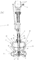
- Fig. 1 is a pump 1, namely a centrifugal pump for Depicted thick matter.
- the pump instructs Drive linkage 2 with a shaft 3 running therein.
- the wave is either direct from one Electric motor drive or an angular gear 4 from an engine, for example a tractor drive, operated.
- the drive linkage 2 is via a holder 5 connected to the housing 6, a spiral housing.
- the continuous shaft 3 drives in the housing 6 arranged impeller 7, which by the upward open inlet 8 pumps incoming liquid.
- the Housing 6 has a lower cover 9, the one has centrally arranged receptacle 10, into which a Support bearing 11 can be used, the shaft 3 in the lower Supported area and thus secures against radial impacts. Furthermore, there is a split ring 12 in the housing 6 intended.
- the parts of the housing 6 are essentially screwed together.
- the Fastened holder 5 which has two struts 15 and 16, which are arranged on opposite sides and in Outline about crown shape.
- the holder 15 is on its lower attachment point 17 in the outer area attached to the housing 6 and extends from there diagonally outwards and upwards.
- the Struts 16 and 17 In the upper area are the Struts 16 and 17 then guided in an arc and extend substantially horizontally to one upper attachment point 18 at which the holder with the Drive linkage 2 is connected.
- the drive linkage 2 has an outer tube 19 which is connected to a ring 20 is jammed.
- the drive linkage 2 is with the holder connected by screw connections.
- Fig. 2 the lower area of the pump is in shown perspective view.
- the spiral pump is also the outlet 28 recognizable.
- the cutting propeller 25 is arranged, which essentially consists of two semicircles that are twisted against each other are so that protruding cutting edges 29 are formed be and by the slope of the individual parts of the Cutting propeller 25 a pressure towards the inlet can be built.
- the supports 15 and 16 of the holder 5 have the of the attachment points 17 and 18 of the Support bulbous shape facing outwards.
Landscapes
- Engineering & Computer Science (AREA)
- Mechanical Engineering (AREA)
- General Engineering & Computer Science (AREA)
- Structures Of Non-Positive Displacement Pumps (AREA)
Abstract
Description
Die Erfindung betrifft eine Pumpe, insbesondere eine Kreiselpumpe für Dickstoffe, mit einem Antriebsgestänge, an dessen unterem Endbereich ein Gehäuse der Pumpe mit einem Halter mit Abstand zum Antriebsgestänge angeordnet ist, wobei das Gehäuse einen nach oben gerichteten Einlauf aufweist.The invention relates to a pump, in particular a Centrifugal pump for thick matter, with a drive linkage, at the lower end of a housing with the pump a holder arranged at a distance from the drive linkage is, with the housing facing upwards Has enema.
Derartige Pumpen werden insbesondere als Güllepumpen verwendet und in Behälter mit abzupumpenden, dickflüssigen Stoffen abgesenkt. Die Pumpe wird bis auf den Boden des Behälters herabgelassen. Durch den nach oben gerichteten Einlauf wird erreicht, daß die auf dem Boden befindlichen Fremdkörper, wie beispielsweise Steine, nicht unmittelbar angesogen werden. Darüber hinaus ergibt sich immer wieder das Problem, daß langfaserige Festpartikel, wie beispielsweise Stroh, an den rechts und links des Einlaufs angeordneten Streben, die die Pumpe mit dem Antriebsgestänge verbinden, hängen bleiben und den offenen Einzugsquerschnitt zusetzen. Such pumps are used in particular as slurry pumps used and in containers with pumpable, viscous substances lowered. The pump is on up lowered the bottom of the container. By after Inlet directed above is achieved that the on the Foreign objects located on the floor, such as Stones, not immediately sucked in. About that In addition, there is always the problem that long-fiber solid particles, such as straw the struts arranged to the right and left of the inlet, that connect the pump to the drive linkage hang stay and close the open feed cross section.
Pumpen der eingangs genannten Art sind beispielsweise aus der DE 196 09 712 A1 und der DE 196 38 080 A1 bekannt.Pumps of the type mentioned are, for example, out known from DE 196 09 712 A1 and DE 196 38 080 A1.
Der Erfindung liegt daher die Aufgabe zugrunde, eine Pumpe der eingangs genannten Art so weiterzuentwickeln, daß die Saugwirkung der Pumpe erhöht wird und ein Zusetzen durch Fremdstoffe wirksam verhindert wird.The invention is therefore based on the object To further develop the pump of the type mentioned at the beginning, that the suction of the pump is increased and a Clogging by foreign substances is effectively prevented.
Die Lösung dieser Aufgabe erfolgt mit einer Pumpe mit den
Merkmalen des Patentanspruchs 1. Weiterhin wird die
Aufgabe insbesondere auch mit einer Pumpe mit den
Merkmalen des Patentanspruchs 7 gelöst. Vorteilhafte
Weiterbildungen der Erfindung sind in den Unteransprüchen
angegeben.This problem is solved with a pump with the
Features of
Nach dem Grundgedanken der Erfindung ist bei einer Pumpe, insbesondere einer Kreiselpumpe für Dickstoffe, mit einem Antriebsgestänge, an dessen unterem Endbereich ein Gehäuse der Pumpe, bzw. die eigentliche Pumpe, mit einem Halter mit Abstand zum Antriebsgestänge angeordnet ist, wobei das Gehäuse einen nach oben gerichteten Einlauf aufweist, der Halter erfindungsgemäß gegenüber einer geraden Linie zwischen den Befestigungspunkten des Halters an dem Antriebsgestänge und dem Gehäuse mit einer nach außen erweiterten Form ausgebildet. Dadurch wird eine Querschnittserweiterung erreicht, so daß ein besonders großer Einlaß für die zu pumpende Flüssigkeit bereitsteht. Daraus folgt einerseits eine größere Saugwirkung und andererseits wird verhindert, daß Feststoffe, wie insbesondere Stroh, den Einlaß zusetzen.According to the basic idea of the invention, in a pump, especially a centrifugal pump for thick matter, with a Drive linkage, at its lower end Pump housing, or the actual pump, with a Holder is arranged at a distance from the drive linkage, the housing having an upward inlet has, the holder according to the invention straight line between the attachment points of the Holder on the drive linkage and the housing with a formed outward shape. This will reached a cross-sectional expansion, so that a particularly large inlet for the liquid to be pumped is ready. On the one hand, this results in a larger one Suction and on the other hand prevents Solids, such as straw in particular, clog the inlet.
Bevorzugterweise ist der Halter im wesentlichen aus zwei Streben gebildet. Diese verbinden die Pumpe mit dem Antriebsgestänge, so daß sich zwischen den Streben lediglich die Antriebswelle erstreckt, die im Inneren des Antriebsgestänges angeordnet ist und in der Pumpe ein Laufrad antreibt. Grundsätzlich ist es auch möglich, drei oder mehr Streben zu verwenden, jedoch wird dadurch der freie Raum zwischen den Streben eingeschränkt und der freie Querschnitt verkleinert. Grundsätzlich ist es daher günstig, so wenig Streben wie möglich zu verwenden. Auch die Verwendung einer einzigen Strebe ist denkbar.The holder is preferably essentially composed of two Striving formed. These connect the pump to the Drive linkage, so that between the struts only the drive shaft that extends inside the Drive linkage is arranged and in the pump Impeller drives. Basically, it is also possible to have three or more struts, but this will make the restricted space between the struts and the free cross section reduced. Basically, it is cheap to use as few struts as possible. Also the use of a single strut is conceivable.
Dabei weist der Halter bevorzugt eine bogenförmig nach außen gerichtete Form auf. Grundsätzlich sind auch eckige Formen denkbar, jedoch ist es bevorzugt, den Halter bogenförmig auszubilden, da dadurch eine höhere Stabilität und eine leichtere Bearbeitung ermöglicht wird. Der Halter ist insbesondere im oberen Bereich nach außen gewölbt und erstreckt sich dann im wesentlichen gerade zu dem unteren Befestigungspunkt an der Pumpe. Der Halter ist dabei im Umriß etwa kronenförmig ausgebildet. Auch andere Formen sind möglich, wie beispielsweise eine Ausbildung jeder Strebe des Halters als Halbkreis.The holder preferably detects an arc exterior shape. Basically, they are also angular Forms conceivable, but it is preferred to use the holder to form an arc, as a result of which a higher Stability and easier editing possible becomes. The holder is particularly in the upper area domed on the outside and then extends essentially straight to the lower attachment point on the pump. The The holder is approximately crown-shaped in outline. Other shapes are also possible, such as one Form each strut of the holder as a semicircle.
Günstigerweise ist der Halter mindestens genauso breit wie die Pumpe ausgebildet. Dadurch wird ein großer Querschnitt des Halters sichergestellt. Insbesondere ist es bevorzugt, den Halter so auszubilden, daß er in seinen größten Außenabmessungen sich bis über das Pumpengehäuse hinaus erstreckt.Conveniently, the holder is at least as wide trained as the pump. This will make a big one Cross section of the holder ensured. In particular is it is preferred to design the holder so that it fits into its largest external dimensions up to the pump housing extends beyond.
Die Pumpe weist bevorzugt ein Spiralgehäuse mit einem darin angeordneten Laufrad auf, so daß ein Einlaß von oben gegeben ist und seitlich der Auslauf aus der Pumpe erfolgt und von dort beispielsweise über einen Schlauch nach oben gepumpt wird. The pump preferably has a spiral housing with a impeller arranged therein, so that an inlet of is given above and on the side the outlet from the pump takes place and from there, for example, via a hose is pumped up.
In einer anderen besonders bevorzugten Weiterbildung der Erfindung, die gleichzeitig als eigenständiger Erfindungsgedanke gesehen werden kann, wird zur Lösung der obengenannten Aufgabe im Bereich des Halters oberhalb des Einlaufs ein Schneidpropeller angeordnet. Dieser zerkleinert zum einen in den Bereich des Einlaufs geratende Feststoffe, die diesen zusetzen könnten, und dient gleichzeitig als erste Pumpstufe, so daß ein erhöhter Pumpendruck erreicht wird.In another particularly preferred development of the Invention that at the same time as an independent Invention can be seen, becomes a solution the above task in the area of the holder above a cutting propeller is arranged at the inlet. This crushed on the one hand in the area of the inlet solid materials that could clog them, and also serves as the first pump stage, so that a increased pump pressure is reached.
Bevorzugt ist der Schneidpropeller von derselben Antriebswelle angetrieben wie ein in der Pumpe angeordnetes Laufrad. Dadurch ist der Aufbau der Pumpe insgesamt besonders einfach. Weiterhin ist es bevorzugt, den Schneidpropeller zweiflügelig auszubilden. Grundsätzlich sind auch andere Propellergestaltungen möglich, jedoch hat sich gezeigt, daß ein zweiflügeliger Schneidpropeller besonders gute Ergebnisse hinsichtlich der Schneidwirkung erbringt.The cutting propeller is preferably the same Drive shaft driven like one in the pump arranged impeller. This is the structure of the pump overall particularly easy. Furthermore, it is preferred design the cutting propeller to have two blades. Other propeller designs are also fundamentally possible, but it has been shown that a double wing Cutting propeller particularly good results in terms of the cutting effect.
In einer bevorzugten Weiterbildung der Erfindung ist an dem Halter ein Schneidring angeordnet, dessen Innenfläche benachbart zu einer Umfangskante des Schneidpropellers ist. Dadurch wird sichergestellt, daß an dem Schneidpropeller keine größeren Teile vorbei zum Einlaß gelangen können. Vielmehr werden Feststoffe zwischen dem Schneidring und dem Schneidpropeller zerkleinert. Dazu ist insbesondere die Umfangskante des Schneidpropellers scharfkantig ausgebildet. Bevorzugt ist auch der obere Eckbereich des Schneidrings als Schneidkante ausgebildet, so daß längere Feststoff, wie beispielsweise Stroh, über diesen Eckbereich gezogen und daran abgeschnitten werden. Der Schneidpropeller ist bevorzugt etwa auf halber Höhe des Halters angeordnet. Dies insbesondere dann, wenn der Halter kronenförmig ausgebildet ist und oberhalb des Schneidpropellers ein vergleichsweise großer Einzugsquerschnitt verbleibt.In a preferred development of the invention is on the holder arranged a cutting ring, the inner surface adjacent to a peripheral edge of the cutting propeller is. This will ensure that Cutting propeller no large parts over to the inlet can reach. Rather, solids between the Cutting ring and the cutting propeller crushed. To is in particular the peripheral edge of the cutting propeller sharp-edged. The upper one is also preferred Corner area of the cutting ring designed as a cutting edge, so that longer solid, such as straw, over this corner area can be drawn and cut off. The cutting propeller is preferably about halfway up arranged of the holder. This is particularly the case if the Holder is crown-shaped and above the Cutting propellers a comparatively large one Feed cross section remains.
In einer anderen Weiterbildung der Erfindung weist die Pumpe ein unteres Stützlager für die Antriebswelle auf. In diesem Stützlager ist die Antriebswelle zusätzlich gelagert, so daß ein Schutz gegen radiale Schläge besteht.In another development of the invention, the Pump up a lower support bearing for the drive shaft. The drive shaft is additional in this support bearing stored so that protection against radial impacts consists.
Nachfolgend wird die Erfindung anhand eines in der Zeichnung dargestellten Ausführungsbeispiels weiter erläutert. Im einzelnen zeigen die schematischen Darstellungen in:
- Fig. 1:
- einen Querschnitt durch eine erfindungsgemäße Pumpe und
- Fig. 2:
- eine perspektivische Ansicht der Pumpe mit dem Halter und dem Antriebsgestänge.
- Fig. 1:
- a cross section through a pump according to the invention and
- Fig. 2:
- a perspective view of the pump with the holder and the drive linkage.
In Fig. 1 ist eine Pumpe 1, nämlich eine Kreiselpumpe für
Dickstoffe dargestellt. Die Pumpe weist ein
Antriebsgestänge 2 mit einer darin laufenden Welle 3 auf.
Die Welle wird entweder direkt von einem
Elektromotorantrieb oder über ein Winkelgetriebe 4 von
einem Motor, beispielsweise einem Traktorantrieb,
betrieben. Das Antriebsgestänge 2 ist über einen Halter 5
mit dem Gehäuse 6, einem Spiralgehäuse, verbunden. Die
durchgehende Welle 3 treibt ein in dem Gehäuse 6
angeordnetes Laufrad 7 an, das die durch den nach oben
offenen Einlaß 8 hereintretende Flüssigkeit pumpt. Das
Gehäuse 6 weist einen unteren Deckel 9 auf, der eine
zentral angeordnete Aufnahme 10 aufweist, in die ein
Stützlager 11 einsetzbar ist, das die Welle 3 im unteren
Bereich abstützt und so gegen radiale Schläge sichert.
Weiterhin ist in dem Gehäuse 6 ein Spaltring 12
vorgesehen. Die Teile des Gehäuses 6 sind im wesentlichen
miteinander verschraubt. An dem Gehäuse 6 ist auch der
Halter 5 befestigt, der zwei Streben 15 und 16 aufweist,
die auf gegenüberliegenden Seiten angeordnet sind und im
Umriß etwa Kronenform aufweisen. Der Halter 15 ist an
seinem unteren Befestigungspunkt 17 im äußeren Bereich
des Gehäuses 6 befestigt und erstreckt sich von dort
schräg nach außen und oben. Im oberen Bereich sind die
Streben 16 und 17 dann bogenförmig nach innen geführt und
erstrecken sich im wesentlichen horizontal zu einem
oberen Befestigungspunkt 18, an dem der Halter mit dem
Antriebsgestänge 2 verbunden ist. Das Antriebsgestänge 2
weist ein äußeres Rohr 19 auf, das mit einem Ring 20
verklemmt wird. Das Antriebsgestänge 2 ist mit dem Halter
durch Schraubverbindungen verbunden. Durch die Form des
Halters 5 und insbesondere der Streben 15 und 16
verbleibt ein großer Einzugsquerschnitt 22, in den die
Flüssigkeit eintreten und die nach oben offene Öffnung 8
des Gehäuses 6 gelangen kann. Durch den großen
Einzugsquerschnitt wird außerdem verhindert, daß sich
Feststoffe, insbesondere faserige Feststoffe in großem
Umfang an den Stützen 16 und 17 festsetzen und den
gesamten Einzugsbereich blockieren. An der Welle 3 ist
auf etwa einem Drittel der Höhe des Halters 5 ein
Schneidpropeller 25 angeordnet, der von der Welle 3
gemeinsam mit dem Laufrad 7 angetrieben wird. Der
Schneidpropeller dient auch als erste Pumpstufe vor dem
Laufrad 7 und führt die Flüssigkeit zu der Öffnung 8. Der
äußere Rand des Schneidpropellers ist zudem scharfkantig
ausgebildet, so daß an diesem Rand, der dicht benachbart
zu einem an dem Halter 5 angeordnetem Schneidring 26
positioniert ist, Feststoffe zerschnitten werden. Zudem
ist der obere Eckbereich 27 des Schneidrings 26
scharfkantig oder zackig ausgebildet, so daß die von dem
Schneidpropeller erfaßten und mitgezogenen Feststoffe an
dieser Schneidkante 27, die umlaufend um den gesamten
Halter ausgebildet ist, zerschnitten werden.In Fig. 1 is a
In Fig. 2 ist der untere Bereich der Pumpe in
perspektivischer Ansicht dargestellt. Bei dem Gehäuse der
Spiralpumpe ist neben dem Einlaß 8 auch der Auslaß 28
erkennbar. Oberhalb des Auslasses 8 ist an der Welle 3
der Schneidpropeller 25 angeordnet, der im wesentlichen
aus zwei Halbkreisen besteht, die gegeneinander verdreht
sind, so daß vorstehende Schneidkanten 29 ausgebildet
werden und durch die Steigung der einzelnen Teile des
Schneidpropellers 25 ein Druck in Richtung des Einlasses
aufgebaut werden kann. Die Stützen 15 und 16 des Halters
5 weisen die von den Befestigungspunkten 17 und 18 der
Stützen nach außen gerichtete bauchige Form auf.In Fig. 2 the lower area of the pump is in
shown perspective view. In the case of the
In addition to the
Claims (14)
dadurch gekennzeichnet,
daß der Halter (5) eine gegenüber einer geraden Linie zwischen den Befestigungspunkten (17, 18) des Halters (5) an dem Antriebsgestänge (2) und dem Gehäuse (6) der Pumpe eine nach außen erweiterte Form aufweist.Pump, in particular a centrifugal pump, for thick matter with a drive linkage (2), at the lower end area of which a housing (6) of the pump with a holder (5) is arranged at a distance from the drive linkage (2), the housing (6) pointing upwards has directed inlet (8),
characterized,
that the holder (5) has a shape that is outward in relation to a straight line between the fastening points (17, 18) of the holder (5) on the drive linkage (2) and the housing (6) of the pump.
Applications Claiming Priority (2)
| Application Number | Priority Date | Filing Date | Title |
|---|---|---|---|
| DE19961196 | 1999-12-18 | ||
| DE19961196A DE19961196A1 (en) | 1999-12-18 | 1999-12-18 | Pump, in particular centrifugal pump for thick matter |
Publications (3)
| Publication Number | Publication Date |
|---|---|
| EP1108894A2 true EP1108894A2 (en) | 2001-06-20 |
| EP1108894A3 EP1108894A3 (en) | 2002-07-17 |
| EP1108894B1 EP1108894B1 (en) | 2004-05-06 |
Family
ID=7933235
Family Applications (1)
| Application Number | Title | Priority Date | Filing Date |
|---|---|---|---|
| EP00126934A Expired - Lifetime EP1108894B1 (en) | 1999-12-18 | 2000-12-08 | Centrifugal pump for viscous materials |
Country Status (4)
| Country | Link |
|---|---|
| EP (1) | EP1108894B1 (en) |
| AT (1) | ATE266151T1 (en) |
| DE (2) | DE19961196A1 (en) |
| DK (1) | DK1108894T3 (en) |
Cited By (1)
| Publication number | Priority date | Publication date | Assignee | Title |
|---|---|---|---|---|
| ITMI20130390A1 (en) * | 2013-03-15 | 2014-09-16 | Euroacque S R L | DESCALER PUMP |
Citations (6)
| Publication number | Priority date | Publication date | Assignee | Title |
|---|---|---|---|---|
| DD79227A (en) * | ||||
| US2714354A (en) * | 1952-09-08 | 1955-08-02 | Orrin E Farrand | Pump |
| DE2040392A1 (en) * | 1970-08-13 | 1972-02-17 | Esterer Ag Maschf | Submersible cutting pump |
| US4650342A (en) * | 1982-10-28 | 1987-03-17 | R. Goodwin International Ltd. | Agitating particulate solids |
| DE3640813A1 (en) * | 1986-05-16 | 1987-11-26 | Emu Unterwasserpumpen Gmbh | Submerged centrifugal pump |
| US5256032A (en) * | 1992-05-26 | 1993-10-26 | Vaugan Co., Inc. | Centrifugal chopper pump |
Family Cites Families (3)
| Publication number | Priority date | Publication date | Assignee | Title |
|---|---|---|---|---|
| DE2901638B1 (en) * | 1979-01-17 | 1979-08-30 | Gascoigne Suedstall Gmbh | Centrifugal pump for liquids mixed with solids |
| DE19609712A1 (en) * | 1996-03-13 | 1997-09-18 | Uts Umwelt Technik Sued Gmbh | Pump especially for waste water containing sludge |
| DE19638080A1 (en) * | 1996-09-19 | 1998-03-26 | Uts Umwelt Technik Sued Gmbh | Pump with torus-shaped housing |
-
1999
- 1999-12-18 DE DE19961196A patent/DE19961196A1/en not_active Withdrawn
-
2000
- 2000-12-08 DE DE50006317T patent/DE50006317D1/en not_active Expired - Fee Related
- 2000-12-08 EP EP00126934A patent/EP1108894B1/en not_active Expired - Lifetime
- 2000-12-08 DK DK00126934T patent/DK1108894T3/en active
- 2000-12-08 AT AT00126934T patent/ATE266151T1/en not_active IP Right Cessation
Patent Citations (6)
| Publication number | Priority date | Publication date | Assignee | Title |
|---|---|---|---|---|
| DD79227A (en) * | ||||
| US2714354A (en) * | 1952-09-08 | 1955-08-02 | Orrin E Farrand | Pump |
| DE2040392A1 (en) * | 1970-08-13 | 1972-02-17 | Esterer Ag Maschf | Submersible cutting pump |
| US4650342A (en) * | 1982-10-28 | 1987-03-17 | R. Goodwin International Ltd. | Agitating particulate solids |
| DE3640813A1 (en) * | 1986-05-16 | 1987-11-26 | Emu Unterwasserpumpen Gmbh | Submerged centrifugal pump |
| US5256032A (en) * | 1992-05-26 | 1993-10-26 | Vaugan Co., Inc. | Centrifugal chopper pump |
Cited By (1)
| Publication number | Priority date | Publication date | Assignee | Title |
|---|---|---|---|---|
| ITMI20130390A1 (en) * | 2013-03-15 | 2014-09-16 | Euroacque S R L | DESCALER PUMP |
Also Published As
| Publication number | Publication date |
|---|---|
| DE50006317D1 (en) | 2004-06-09 |
| EP1108894A3 (en) | 2002-07-17 |
| DE19961196A1 (en) | 2001-06-28 |
| DK1108894T3 (en) | 2004-08-30 |
| EP1108894B1 (en) | 2004-05-06 |
| ATE266151T1 (en) | 2004-05-15 |
Similar Documents
| Publication | Publication Date | Title |
|---|---|---|
| DE102005014348B3 (en) | Pump, e.g. for machine tools for supplying cooling lubricant emulsions polluted with metal filings, has a cutting running wheel, associated counter blades and a coarse-crusher | |
| EP1462658B1 (en) | Radial fan | |
| EP1797327B1 (en) | Rotary piston pump comprising a pump housing and two double-bladed rotary pistons | |
| DE10327574B4 (en) | Impeller for a fuel pump | |
| DE2117641A1 (en) | Device for crushing and pumping out pumpable waste | |
| DE2500860A1 (en) | DIGESTION DEVICE | |
| DE10327573A1 (en) | Single stage flow pump | |
| EP3179112B1 (en) | Pump cover plate with through holes that are designed as inertial filters | |
| DE112004001198T5 (en) | Impeller blade assembly for a centrifugal pump | |
| DE69922198T2 (en) | CENTRIFUGAL PUMP | |
| DE102006042990B3 (en) | Strainer | |
| DE69731091T2 (en) | ROTODYNAMIC PUMP | |
| EP1213517B1 (en) | Mechanical seal for fluid-flow machines | |
| DE4438841C2 (en) | Pump with a cutting device | |
| DE1959262B2 (en) | Vertical-axis aeration gyro for aeration of wastewater or the same liquids | |
| DE19510811A1 (en) | Fiber-repellent wall surface design | |
| EP1108894B1 (en) | Centrifugal pump for viscous materials | |
| DE4321653A1 (en) | Hand blender | |
| DE3238647A1 (en) | Mixer | |
| DE3640813A1 (en) | Submerged centrifugal pump | |
| DE1528651B2 (en) | Dirty water pump | |
| DE6921357U (en) | SEWAGE PUMP | |
| DE3141578A1 (en) | DEVICE FOR PUMPING FOAMING LIQUIDS | |
| EP1161630B1 (en) | Comminuting pump | |
| DE2942302C2 (en) | Suction head for a suction pipe for pumping sediments from the seabed |
Legal Events
| Date | Code | Title | Description |
|---|---|---|---|
| PUAI | Public reference made under article 153(3) epc to a published international application that has entered the european phase |
Free format text: ORIGINAL CODE: 0009012 |
|
| AK | Designated contracting states |
Kind code of ref document: A2 Designated state(s): AT BE CH CY DE DK ES FI FR GB GR IE IT LI LU MC NL PT SE TR |
|
| AX | Request for extension of the european patent |
Free format text: AL;LT;LV;MK;RO;SI |
|
| PUAL | Search report despatched |
Free format text: ORIGINAL CODE: 0009013 |
|
| AK | Designated contracting states |
Kind code of ref document: A3 Designated state(s): AT BE CH CY DE DK ES FI FR GB GR IE IT LI LU MC NL PT SE TR |
|
| AX | Request for extension of the european patent |
Free format text: AL;LT;LV;MK;RO;SI |
|
| 17P | Request for examination filed |
Effective date: 20020716 |
|
| 17Q | First examination report despatched |
Effective date: 20021112 |
|
| AKX | Designation fees paid |
Designated state(s): AT BE CH CY DE DK ES FI FR GB GR IE IT LI LU MC NL PT SE TR |
|
| GRAP | Despatch of communication of intention to grant a patent |
Free format text: ORIGINAL CODE: EPIDOSNIGR1 |
|
| GRAS | Grant fee paid |
Free format text: ORIGINAL CODE: EPIDOSNIGR3 |
|
| GRAA | (expected) grant |
Free format text: ORIGINAL CODE: 0009210 |
|
| AK | Designated contracting states |
Kind code of ref document: B1 Designated state(s): AT BE CH CY DE DK ES FI FR GB GR IE IT LI LU MC NL PT SE TR |
|
| PG25 | Lapsed in a contracting state [announced via postgrant information from national office to epo] |
Ref country code: IT Free format text: LAPSE BECAUSE OF FAILURE TO SUBMIT A TRANSLATION OF THE DESCRIPTION OR TO PAY THE FEE WITHIN THE PRESCRIBED TIME-LIMIT;WARNING: LAPSES OF ITALIAN PATENTS WITH EFFECTIVE DATE BEFORE 2007 MAY HAVE OCCURRED AT ANY TIME BEFORE 2007. THE CORRECT EFFECTIVE DATE MAY BE DIFFERENT FROM THE ONE RECORDED. Effective date: 20040506 Ref country code: NL Free format text: LAPSE BECAUSE OF FAILURE TO SUBMIT A TRANSLATION OF THE DESCRIPTION OR TO PAY THE FEE WITHIN THE PRESCRIBED TIME-LIMIT Effective date: 20040506 Ref country code: FR Free format text: LAPSE BECAUSE OF FAILURE TO SUBMIT A TRANSLATION OF THE DESCRIPTION OR TO PAY THE FEE WITHIN THE PRESCRIBED TIME-LIMIT Effective date: 20040506 Ref country code: CY Free format text: LAPSE BECAUSE OF FAILURE TO SUBMIT A TRANSLATION OF THE DESCRIPTION OR TO PAY THE FEE WITHIN THE PRESCRIBED TIME-LIMIT Effective date: 20040506 Ref country code: FI Free format text: LAPSE BECAUSE OF FAILURE TO SUBMIT A TRANSLATION OF THE DESCRIPTION OR TO PAY THE FEE WITHIN THE PRESCRIBED TIME-LIMIT Effective date: 20040506 Ref country code: GB Free format text: LAPSE BECAUSE OF FAILURE TO SUBMIT A TRANSLATION OF THE DESCRIPTION OR TO PAY THE FEE WITHIN THE PRESCRIBED TIME-LIMIT Effective date: 20040506 Ref country code: ES Free format text: LAPSE BECAUSE OF FAILURE TO SUBMIT A TRANSLATION OF THE DESCRIPTION OR TO PAY THE FEE WITHIN THE PRESCRIBED TIME-LIMIT Effective date: 20040506 Ref country code: TR Free format text: LAPSE BECAUSE OF FAILURE TO SUBMIT A TRANSLATION OF THE DESCRIPTION OR TO PAY THE FEE WITHIN THE PRESCRIBED TIME-LIMIT Effective date: 20040506 Ref country code: IE Free format text: LAPSE BECAUSE OF FAILURE TO SUBMIT A TRANSLATION OF THE DESCRIPTION OR TO PAY THE FEE WITHIN THE PRESCRIBED TIME-LIMIT Effective date: 20040506 |
|
| REG | Reference to a national code |
Ref country code: GB Ref legal event code: FG4D Free format text: NOT ENGLISH |
|
| REG | Reference to a national code |
Ref country code: CH Ref legal event code: EP |
|
| REF | Corresponds to: |
Ref document number: 50006317 Country of ref document: DE Date of ref document: 20040609 Kind code of ref document: P |
|
| REG | Reference to a national code |
Ref country code: IE Ref legal event code: FG4D Free format text: GERMAN |
|
| PG25 | Lapsed in a contracting state [announced via postgrant information from national office to epo] |
Ref country code: GR Free format text: LAPSE BECAUSE OF FAILURE TO SUBMIT A TRANSLATION OF THE DESCRIPTION OR TO PAY THE FEE WITHIN THE PRESCRIBED TIME-LIMIT Effective date: 20040806 Ref country code: SE Free format text: LAPSE BECAUSE OF FAILURE TO SUBMIT A TRANSLATION OF THE DESCRIPTION OR TO PAY THE FEE WITHIN THE PRESCRIBED TIME-LIMIT Effective date: 20040806 |
|
| REG | Reference to a national code |
Ref country code: DK Ref legal event code: T3 |
|
| NLV1 | Nl: lapsed or annulled due to failure to fulfill the requirements of art. 29p and 29m of the patents act | ||
| GBV | Gb: ep patent (uk) treated as always having been void in accordance with gb section 77(7)/1977 [no translation filed] |
Effective date: 20040506 |
|
| PG25 | Lapsed in a contracting state [announced via postgrant information from national office to epo] |
Ref country code: LU Free format text: LAPSE BECAUSE OF NON-PAYMENT OF DUE FEES Effective date: 20041208 |
|
| REG | Reference to a national code |
Ref country code: IE Ref legal event code: FD4D |
|
| PG25 | Lapsed in a contracting state [announced via postgrant information from national office to epo] |
Ref country code: MC Free format text: LAPSE BECAUSE OF NON-PAYMENT OF DUE FEES Effective date: 20041231 Ref country code: CH Free format text: LAPSE BECAUSE OF NON-PAYMENT OF DUE FEES Effective date: 20041231 Ref country code: LI Free format text: LAPSE BECAUSE OF NON-PAYMENT OF DUE FEES Effective date: 20041231 Ref country code: BE Free format text: LAPSE BECAUSE OF NON-PAYMENT OF DUE FEES Effective date: 20041231 |
|
| PLBE | No opposition filed within time limit |
Free format text: ORIGINAL CODE: 0009261 |
|
| STAA | Information on the status of an ep patent application or granted ep patent |
Free format text: STATUS: NO OPPOSITION FILED WITHIN TIME LIMIT |
|
| EN | Fr: translation not filed | ||
| 26N | No opposition filed |
Effective date: 20050208 |
|
| BERE | Be: lapsed |
Owner name: *STALLKAMP ERICH Effective date: 20041231 |
|
| REG | Reference to a national code |
Ref country code: CH Ref legal event code: PL |
|
| BERE | Be: lapsed |
Owner name: *STALLKAMP ERICH Effective date: 20041231 |
|
| PG25 | Lapsed in a contracting state [announced via postgrant information from national office to epo] |
Ref country code: PT Free format text: LAPSE BECAUSE OF NON-PAYMENT OF DUE FEES Effective date: 20041006 |
|
| PGFP | Annual fee paid to national office [announced via postgrant information from national office to epo] |
Ref country code: DK Payment date: 20071220 Year of fee payment: 8 |
|
| PGFP | Annual fee paid to national office [announced via postgrant information from national office to epo] |
Ref country code: AT Payment date: 20071220 Year of fee payment: 8 |
|
| PGFP | Annual fee paid to national office [announced via postgrant information from national office to epo] |
Ref country code: DE Payment date: 20071018 Year of fee payment: 8 |
|
| REG | Reference to a national code |
Ref country code: DK Ref legal event code: EBP |
|
| PG25 | Lapsed in a contracting state [announced via postgrant information from national office to epo] |
Ref country code: AT Free format text: LAPSE BECAUSE OF NON-PAYMENT OF DUE FEES Effective date: 20081208 |
|
| PG25 | Lapsed in a contracting state [announced via postgrant information from national office to epo] |
Ref country code: DE Free format text: LAPSE BECAUSE OF NON-PAYMENT OF DUE FEES Effective date: 20090701 |
|
| PG25 | Lapsed in a contracting state [announced via postgrant information from national office to epo] |
Ref country code: DK Free format text: LAPSE BECAUSE OF NON-PAYMENT OF DUE FEES Effective date: 20090105 |