EP1108847A1 - Rahmenloser Glasflügel - Google Patents
Rahmenloser Glasflügel Download PDFInfo
- Publication number
- EP1108847A1 EP1108847A1 EP00127685A EP00127685A EP1108847A1 EP 1108847 A1 EP1108847 A1 EP 1108847A1 EP 00127685 A EP00127685 A EP 00127685A EP 00127685 A EP00127685 A EP 00127685A EP 1108847 A1 EP1108847 A1 EP 1108847A1
- Authority
- EP
- European Patent Office
- Prior art keywords
- glass
- door
- closure element
- panes
- spacer
- Prior art date
- Legal status (The legal status is an assumption and is not a legal conclusion. Google has not performed a legal analysis and makes no representation as to the accuracy of the status listed.)
- Granted
Links
- 241000591215 Acraea andromacha Species 0.000 title claims description 20
- 239000011521 glass Substances 0.000 claims abstract description 72
- 125000006850 spacer group Chemical group 0.000 claims abstract description 38
- 230000000149 penetrating effect Effects 0.000 claims 1
- 238000010276 construction Methods 0.000 description 4
- 210000002414 leg Anatomy 0.000 description 3
- 238000005452 bending Methods 0.000 description 1
- 238000011109 contamination Methods 0.000 description 1
- 239000002274 desiccant Substances 0.000 description 1
- 239000005357 flat glass Substances 0.000 description 1
- 238000007373 indentation Methods 0.000 description 1
- 238000009434 installation Methods 0.000 description 1
- 210000000689 upper leg Anatomy 0.000 description 1
Images


Classifications
-
- E—FIXED CONSTRUCTIONS
- E06—DOORS, WINDOWS, SHUTTERS, OR ROLLER BLINDS IN GENERAL; LADDERS
- E06B—FIXED OR MOVABLE CLOSURES FOR OPENINGS IN BUILDINGS, VEHICLES, FENCES OR LIKE ENCLOSURES IN GENERAL, e.g. DOORS, WINDOWS, BLINDS, GATES
- E06B3/00—Window sashes, door leaves, or like elements for closing wall or like openings; Layout of fixed or moving closures, e.g. windows in wall or like openings; Features of rigidly-mounted outer frames relating to the mounting of wing frames
- E06B3/02—Wings made completely of glass
- E06B3/025—Wings made completely of glass consisting of multiple glazing units
-
- E—FIXED CONSTRUCTIONS
- E05—LOCKS; KEYS; WINDOW OR DOOR FITTINGS; SAFES
- E05B—LOCKS; ACCESSORIES THEREFOR; HANDCUFFS
- E05B65/00—Locks or fastenings for special use
- E05B65/0025—Locks or fastenings for special use for glass wings
-
- E—FIXED CONSTRUCTIONS
- E05—LOCKS; KEYS; WINDOW OR DOOR FITTINGS; SAFES
- E05D—HINGES OR SUSPENSION DEVICES FOR DOORS, WINDOWS OR WINGS
- E05D5/00—Construction of single parts, e.g. the parts for attachment
- E05D5/02—Parts for attachment, e.g. flaps
- E05D5/0246—Parts for attachment, e.g. flaps for attachment to glass panels
-
- E—FIXED CONSTRUCTIONS
- E05—LOCKS; KEYS; WINDOW OR DOOR FITTINGS; SAFES
- E05D—HINGES OR SUSPENSION DEVICES FOR DOORS, WINDOWS OR WINGS
- E05D7/00—Hinges or pivots of special construction
- E05D7/08—Hinges or pivots of special construction for use in suspensions comprising two spigots placed at opposite edges of the wing, especially at the top and the bottom, e.g. trunnions
- E05D7/081—Hinges or pivots of special construction for use in suspensions comprising two spigots placed at opposite edges of the wing, especially at the top and the bottom, e.g. trunnions the pivot axis of the wing being situated near one edge of the wing, especially at the top and bottom, e.g. trunnions
-
- E—FIXED CONSTRUCTIONS
- E05—LOCKS; KEYS; WINDOW OR DOOR FITTINGS; SAFES
- E05Y—INDEXING SCHEME ASSOCIATED WITH SUBCLASSES E05D AND E05F, RELATING TO CONSTRUCTION ELEMENTS, ELECTRIC CONTROL, POWER SUPPLY, POWER SIGNAL OR TRANSMISSION, USER INTERFACES, MOUNTING OR COUPLING, DETAILS, ACCESSORIES, AUXILIARY OPERATIONS NOT OTHERWISE PROVIDED FOR, APPLICATION THEREOF
- E05Y2800/00—Details, accessories and auxiliary operations not otherwise provided for
- E05Y2800/20—Combinations of elements
- E05Y2800/205—Combinations of elements forming a unit
-
- E—FIXED CONSTRUCTIONS
- E05—LOCKS; KEYS; WINDOW OR DOOR FITTINGS; SAFES
- E05Y—INDEXING SCHEME ASSOCIATED WITH SUBCLASSES E05D AND E05F, RELATING TO CONSTRUCTION ELEMENTS, ELECTRIC CONTROL, POWER SUPPLY, POWER SIGNAL OR TRANSMISSION, USER INTERFACES, MOUNTING OR COUPLING, DETAILS, ACCESSORIES, AUXILIARY OPERATIONS NOT OTHERWISE PROVIDED FOR, APPLICATION THEREOF
- E05Y2800/00—Details, accessories and auxiliary operations not otherwise provided for
- E05Y2800/20—Combinations of elements
- E05Y2800/21—Combinations of elements of identical elements, e.g. of identical compression springs
-
- E—FIXED CONSTRUCTIONS
- E05—LOCKS; KEYS; WINDOW OR DOOR FITTINGS; SAFES
- E05Y—INDEXING SCHEME ASSOCIATED WITH SUBCLASSES E05D AND E05F, RELATING TO CONSTRUCTION ELEMENTS, ELECTRIC CONTROL, POWER SUPPLY, POWER SIGNAL OR TRANSMISSION, USER INTERFACES, MOUNTING OR COUPLING, DETAILS, ACCESSORIES, AUXILIARY OPERATIONS NOT OTHERWISE PROVIDED FOR, APPLICATION THEREOF
- E05Y2800/00—Details, accessories and auxiliary operations not otherwise provided for
- E05Y2800/67—Materials; Strength alteration thereof
- E05Y2800/672—Glass
-
- E—FIXED CONSTRUCTIONS
- E05—LOCKS; KEYS; WINDOW OR DOOR FITTINGS; SAFES
- E05Y—INDEXING SCHEME ASSOCIATED WITH SUBCLASSES E05D AND E05F, RELATING TO CONSTRUCTION ELEMENTS, ELECTRIC CONTROL, POWER SUPPLY, POWER SIGNAL OR TRANSMISSION, USER INTERFACES, MOUNTING OR COUPLING, DETAILS, ACCESSORIES, AUXILIARY OPERATIONS NOT OTHERWISE PROVIDED FOR, APPLICATION THEREOF
- E05Y2900/00—Application of doors, windows, wings or fittings thereof
-
- E—FIXED CONSTRUCTIONS
- E05—LOCKS; KEYS; WINDOW OR DOOR FITTINGS; SAFES
- E05Y—INDEXING SCHEME ASSOCIATED WITH SUBCLASSES E05D AND E05F, RELATING TO CONSTRUCTION ELEMENTS, ELECTRIC CONTROL, POWER SUPPLY, POWER SIGNAL OR TRANSMISSION, USER INTERFACES, MOUNTING OR COUPLING, DETAILS, ACCESSORIES, AUXILIARY OPERATIONS NOT OTHERWISE PROVIDED FOR, APPLICATION THEREOF
- E05Y2900/00—Application of doors, windows, wings or fittings thereof
- E05Y2900/10—Application of doors, windows, wings or fittings thereof for buildings or parts thereof
- E05Y2900/13—Type of wing
- E05Y2900/132—Doors
Definitions
- the invention relates to a frameless glass wing as a movably mounted or fixed wing of a door, a window or a facade or glass wall with at least two glass panes with the features of the preamble of the claim 1.
- DE 44 00 196 C1 describes a frameless glass door consisting of two spaced parallel to each other by a circumferential spacer Slices. This creates free space for installation in the outer area of the panes fittings, e.g. Door locks, formed.
- the door lock is by means of a mounting plate attached in the space between the panes and an external one Pressure plate through an opening of the disc with a screw braced against each other, fixed to the disc.
- the attachment is similar from external fittings, e.g. a hinge band. This rests on the outside of the pane and is penetrated by a pane Threaded bolt with a nut in the space between the washers on the washer fixed. In both cases, by fastening the fittings in the area around the openings in the glass panes local pressure forces on the pane exercised.
- DE 195 12 520 C1 builds on DE 44 00 196 C1.
- the holding profile is glued to the smaller pane.
- a carrier plate is inserted, with the external fittings through Openings in the panes are clamped through. Both carrier plate as external fittings also exert local pressure on the panes.
- DE 43 43 521 A1 describes a window or door construction consisting of at least two glass panes and circumferential spacers described.
- U-profile parts in the space between the panes are used to fasten fittings along the entire circumference of the glass panes.
- Outside fittings are connected to the U-profiles through openings in the panes and so fixed on the glass wing. They also exert local pressure on the Disks out.
- the object of the invention is therefore to be external or at least partially external Fittings on glass wings consisting of two parallel panes, where recesses, e.g. Access openings in the panes are inevitable are to be attached in such a way that no local pressure or forces are exerted on the glass panes be exercised.
- the object is achieved according to the invention by the subject of the indicator of claim 1.
- the spacer between the fitting and the support and / or edge closure element are the compressive forces caused by the fitting part is supported on the support and / or edge closure element guided and not on the glass pane itself. Since the wearing and / or edge closure element over a large area with the glass panes connected, e.g. the pressure forces are also glued to a large area distributed so that only very low stresses can arise in the glass.
- the Spacer can also be between the fitting part and one with the carrying and / or part of the edge closure element or another, between the disc arranged part can be arranged.
- the spacer is preferably designed as a separate part; but it can also be firmly connected to the fitting part.
- the spacer is preferred shaped as a sleeve or the like, the shape of which rests on the edge of the recess in the glass pane.
- the invention is particularly advantageous when fastening door handles, preferably Doorknobs on a glass door.
- the door handles must face each other each supported on the outside of the glass panes and supported by Recesses in the glass panes through a pawl axis with each other be connected.
- the two door handles are preferably used here Screws clamped against each other, which are preferably recesses in the Reach through panes and in a thread in the other door handle or in this surrounding rosette are anchored.
- the screw forces are also here derived via the spacers on the support and / or edge finishing element.
- the revolving door leaf 1 shown in Figure 1 has two mutually parallel, in Embodiment of equal size and completely overlapping each other Glass panes 1a, 1b (see Figure 4).
- the glass panes 1a, 1b are through a at a distance from the horizontal and vertical edges of the revolving door leaf 1 circumferential spacers 6 (see Figure 5) connected to each other in the figures 1 and 4 it is not shown.
- the spacer 6 is trained as a profile. It can be a desiccant containing profile with openings be formed towards the interior 1c.
- He is preferably in one constant distance to the outer edges of the glass panes 1a, 1b, see above that in the edge area of the panes 1a, 1b there is an open space open to the outside arises.
- this free space there are a support and / or edge closure element 5 as well as fitting parts used.
- the fittings are on the support and / or edge trim 5 attached.
- the fittings and the support and / or edge closure element 5 are so far they are arranged between the glass panes 1a, 1b, in each case by edge printing the panes 1a, 1b are covered in this area and thus from the outside not visible.
- the support and / or edge finishing element 5 also directly adjoin the spacer 6 or in one piece be carried out with the spacer 6.
- the revolving door leaf 1 is pivotable about an axis of rotation 2, which is inside the door leaf 1 runs and in an upper pin band 7 and a lower pin band 8 ends.
- the door is over the upper hinge 7 and the lower hinge 8 in journal bearings, not shown, in a likewise not shown stationary door frame or a stationary one forming the door frame Facade inserted and rotatably mounted.
- the lower one Floor store a floor closer should be available.
- the door has a door handle 3 on each side for actuating one Schnäppers 31 on.
- the catch 31 engages in the closed position of the door leaf 1 in the fixed door frame arranged, not shown locking plate.
- For Locking is used by a lock with a bolt.
- the keyhole is shown in FIG 41 and the locking bolt 42 (extended in the figure), a corresponding one Bolt receptacle, not shown, faces in the fixed frame.
- a support and / or edge closure element 5 are each along the vertical Door edges running vertical profiles 5a, 5b and along the horizontal door edges running horizontal profiles 5c, 5d provided with the glass panes 1a, 1b are firmly connected, for example glued.
- the four profiles 5a, 5b, 5c, 5d form an inner rectangular one arranged between the panes Frame. The ends of the profile that meet in the corner areas of the frame are connected by screws, not shown.
- the top horizontal profile 5c is recessed in the area of the corner lying at the door axis, in the recess, the upper pin band 7 is arranged and with the adjacent ones Ends of the ceiling-side horizontal profile 5c and of the door axis vertical profile 5a non-positively by one fastening device each 71, 72 connected.
- the profiles 5a, 5b, 5c, 5d each have the shape of a slightly modified cross section U.
- the outer sides of the two legs of the U are on the glass panes 1a, 1b and are glued to them.
- the U-legs have something Longitudinal webs 52 on both inner walls above the center.
- the Leg ends 53 are on the edge of the pane to protect it from the outside bent and connected by a web 54.
- This web 54 points like the baseline, an indentation facing the inside of the U, so that also on this side an outwardly open longitudinal groove 55 is formed.
- These can e.g. Brushes must be inserted, the space between the closing edges of door 1 and seal the stationary frame.
- the profile 5b is changed; and that is in the area the lock case 4, the outer connecting web between the U-legs recessed, also the entire inner bottom is milled away.
- the profile 5b is here reduced to the front part of the U-leg with the longitudinal webs 52 and the ends bent over the edges of the pane. The outside the legs are glued to the inside of the glass panes 1a, 1b.
- a U-profile 9 is in the space between the panes 1c with in Towards the main closing edge of the open side further towards the The interior of the door is offset. It is above and below the lock case 4 with the adjacent ends of the support and / or edge closure element 5 non-positively connected by screws 91. Also with this profile 9 are the outer sides of the U-legs with the inner sides of the glass panes 1a, 1b glued.
- the spacer 6 can also further inside in the lock case area the door 1 is offset and guided around the lock case 4 and the U-profile 9 his.
- the lock case 4 used between the glass panes 1a, 1b in the receiving space between the U-profile 9 and the modified support and / or edge closure element 5 .
- the support and / or edge finishing element 5 be designed with such a large groove that the lock case 4 in the receiving groove can be used and on the U-profile 9 is in this case can be dispensed with.
- the lock case 4 has recesses for bolts 42 and spring-loaded catch 31 and on its front recesses for the key and the door handle 3 and contains the lock case inside 43 with catch 31 and bolt 42. That of the main door closing edge facing end of the lock case 43 is extended up and down and thus forms tabs 44 which are connected to the adjacent ends of the carrying and / or edge closure element 5 are screwed.
- the lock case 43 with locking bolt 42 can only be a fixed, between the Disks 1a, 1b arranged snap box can be provided, in which the spring-loaded catch 31 and the door handle 3 or door handles 3 engage.
- a separate lock case can also be used 4 with locking bolts 42 and a separate catch box with catch 31 may be provided.
- the glass panes 1a, 1b are attached to the corresponding ones Cut out places to reach through the jack axes, each at the connection end the door handles 3 are formed.
- the handle axis of the door handle 3 passes through each of the disks 1a, 1b on the one facing the respective door handle 3 Side of door leaf 1 and engages in the lock in lock case 43 on.
- the lock carries a doorknob 3 on both outer sides, i.e. so on Both sides of the lock grip the door handles 3 to actuate the catch 31 a.
- a rosette 32a, 32b surrounds the Connection ends of the door handles 3.
- the rosettes 32a, 32b have an elongated elliptical Shape with the longer axis in the vertical direction (see Figure 2 and Figure 5).
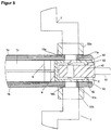
- the two rosettes 32a, 32b mutually braced by two screws 33a, 33b, the screws 33a, 33b both a rosette 32a, the first glass panel 1a, the lock case 43 and reach through the second glass pane 1b and in a thread in the other rosette 32b are screwed.
- the two screws 33a, 33b are located itself above and below the door handle 3 and are therefore only indicated in FIG. 1, however, not visible in FIG. 5.
- the disks 1a, 1b have through holes.
- the spacer sleeves 10a, 10b are each between rosette 32a, 32b and support and / or edge closure element 5 or U-profile 9 arranged, i.e.
- one end of the spacer sleeve 10a, 10b lies on the underside of the rosette 32a, 32b and the other end on the top of the support and / or edge closure element 5 and the U-profile 9.
- the Spacer sleeves 10a, 10b therefore do not transmit the screw force to the glass panes 1a, 1b, but on the support and / or edge closure element 5 and the U-profile 9 in the disc space 1c.
- the spacers 10a, 10b can also directly on support the lock case 4 if it is designed to be stable.
- the Spacers 10a, 10b can also be integrated in the door handle 3, that is be made in one piece with it.
- the spacer sleeves 10a, 10b also in one piece with the lock case 4 or the carrying and / or edge closure element 5 or the U-profile 9 may be formed.
- a handle 3 can also be present only on one side of the door.
- the secure attachment can then be screwed directly onto the carrying and Edge finishing element 5 and / or the U-profile 9 or the lock case 4 or snap box or on one on the other side of the door Fitting part, which then takes over the task of the door handle rosette 32a, 32b.
Landscapes
- Engineering & Computer Science (AREA)
- Mechanical Engineering (AREA)
- Civil Engineering (AREA)
- Structural Engineering (AREA)
- Securing Of Glass Panes Or The Like (AREA)
- Transition And Organic Metals Composition Catalysts For Addition Polymerization (AREA)
- Glass Compositions (AREA)
- Materials For Medical Uses (AREA)
- Refrigerator Housings (AREA)
Abstract
Description
- Figur 1
- einen vertikalen frontseitigen Schnitt durch die Tür in ihrer Mittelebene ohne Türgriff;
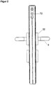
- Figur 2
- eine Draufsicht auf die vertikale Nebenschlusskante der Tür;
- Figur 3
- eine Draufsicht auf die Türoberkante;
- Figur 4
- einen horizontalen Schnitt durch die Tür im Bereich der Hauptschließkante außerhalb des Türgriffs;
- Figur 5
- detailliert den horizontalen Schnitt im Türschloss- und Griffbereich.
- 1
- Drehtürflügel
- 1a
- Glasscheibe
- 1b
- Glasscheibe
- 1c
- Innenraum
- 2
- Drehachse
- 3
- Türklinke
- 4
- Schlosskasten
- 5
- Trage- und/oder Randabschlusselement
- 5a
- vertikales Profil
- 5b
- vertikales Profil
- 5c
- horizontales Profil
- 5d
- horizontales Profil
- 6
- Abstandshalter
- 7
- oberes Zapfenband
- 8
- unteres Zapfenband
- 9
- U-Profil
- 10a
- Distanzstück
- 10b
- Distanzstück
- 11a
- Dichtung
- 11b
- Dichtung
- 31
- Schnäpper
- 32a
- Rosette
- 32b
- Rosette
- 33a
- Schraube
- 33b
- Schraube
- 41
- Schlüsselloch
- 42
- Riegelbolzen
- 43
- Schlosskasten
- 52
- Längssteg
- 53
- Schenkelende
- 54
- Steg
- 55
- Längsnut
- 71
- Befestigungsvorrichtung
- 72
- Befestigungsvorrichtung
- 81
- Befestigungsvorrichtung
- 91
- Schraube
Claims (15)
- Rahmenloser Glasflügel (1), d.h. Glasflügel (1) ohne äußeren aufliegenden Rahmen, als bewegbar gelagerter oder ortsfester Flügel (1) einer Tür, eines Fensters oder einer Fassade oder Glaswand,dadurch gekennzeichnet,mit zumindest zwei parallel angeordneten Glasscheiben (1a, 1b),mit einem zwischen den Glasscheiben (1a, 1b) umlaufenden Abstandshalter (6) und/oder mit einem im Randbereich der Glasscheiben (1a, 1b), vorzugsweise zwischen den Glasscheiben (1a, 1b), angeordneten Trage- und/oder Randabschlusselement (5), vorzugsweise zur Befestigung eines Beschlagteils,wobei vorzugsweise vorgesehen ist, dass das Trage- und/oder Randabschlusselement (5) und/oder das Beschlagteil von mindestens einer der Glasscheiben (1a, 1b) in Blickrichtung senkrecht auf die Flügelebene zumindest teilweise überlappt wird bzw. werden,und wobei vorzugsweise vorgesehen ist, dass der Abstandshalter (6) und das Trage- und/oder Randabschlusselement (5) separat mit Abstand zueinander oder einstückig ausgebildet sind,
dass das Beschlagteil zumindest teilweise an einer Außenseite einer der Glasscheiben (1a, 1b) angeordnet ist und auf dem Trage- und/oder Randabschlusselement (5) oder einem damit verbundenen, zwischen den Glasscheiben (1a, 1b) angeordneten Teil oder einem anderen, zwischen den Glasscheiben (1a, 1b) angeordneten Teil abgestützt ist, indem zwischen dem Beschlagteil und dem Trage- und/oder Randabschlusselement (5) oder dem damit verbundenen Teil oder dem anderen zwischen den Glasscheiben (1a, 1b) angeordneten Teil ein Distanzstück (10a, 10b) in einer Ausnehmung der Glasscheibe (1a, 1b) angeordnet ist, wobei die Erstreckung des Distanzstücks (10a, 10b) senkrecht zur Glasscheibenebene gerichtet größer ist als die Dicke der Glasscheibe (1a, 1b). - Glasflügel nach Anspruch 1,
dadurch gekennzeichnet, dass das Distanzstück (10a, 10b) mit dem Beschlagteil oder mit dem Trage- und/oder Randabschlusselement (5) oder mit dem damit verbundenen Teil oder mit dem anderen Teil fest verbunden ist, vorzugsweise einstückig verbunden ist oder als von diesen separat ausgebildetes Teil ausgebildet ist. - Glasflügel nach Anspruch 2,
dadurch gekennzeichnet, dass das Distanzstück (10a, 10b) als hülsenartiger Körper, in seiner Form an den Rand der Ausnehmung in der Glasscheibe (1a, 1b) angepasst, ausgebildet ist. - Glasflügel nach Anspruch 3,
dadurch gekennzeichnet, dass zwischen Distanzstück (10a, 10b) und dem Rand der Ausnehmung in der Glasscheibe (1a, 1b) eine Dichtung (11a, 11b) angeordnet ist. - Glasflügel nach einem der Ansprüche 1 bis 4,
dadurch gekennzeichnet, dass zwischen dem außenliegenden Beschlagteil und der Außenseite der Glasscheibe (1a, 1b) eine Dichtung angeordnet ist. - Glasflügel nach einem der vorangehenden Ansprüche,
dadurch gekennzeichnet, dass es sich bei dem Beschlagteil um einen Türgriff, vorzugsweise eine Türklinke (3) handelt. - Glasflügel nach einem der vorhergehenden Ansprüche,
dadurch gekennzeichnet, dass zu dem Beschlagteil auf der gegenüberliegenden Seite des Flügels (1) an der anderen Glasscheibe (1a, 1b) ebenfalls ein außenliegendes Beschlagteil, das auch auf dem Trage- und/oder Randabschlusselement (5) oder einem damit verbundenen, zwischen den Glasscheiben (1a, 1b) angeordneten Teil oder einem anderen, zwischen den Glasscheiben (1a, 1b) angeordneten Teil ebenfalls über ein Distanzstück (10a, 10b) abgestützt ist, angeordnet ist. - Glasflügel nach Anspruch 7,
dadurch gekennzeichnet, dass die beiden Beschlagteile gegeneinander durch beide Glasscheiben (1a, 1b) durchgreifende Schrauben abgestützt sind, wobei sich in mindestens einem der Beschlagteile ein Gewinde zur Aufnahme der Schrauben befindet. - Glasflügel nach Anspruch 8,
dadurch gekennzeichnet, dass es sich bei den beiden Beschlagteilen um Türgriffe, vorzugsweise Türklinken (3), vorzugsweise mit umgebender Rosette (32a, 32b) handelt, die auf einer Türgriffachse vorzugsweise Klinkenachse angeordnet sind, die durch die zwei Glasscheiben (1a, 1b) hindurchgreift. - Glasflügel nach Anspruch 9,
dadurch gekennzeichnet, dass im Bereich der beiden Türgriffe (3) im Zwischenraum (1c) zwischen den Glasscheiben (1a, 1b) ein Schlosskasten (4, 43) angeordnet ist. - Glasflügel nach Anspruch 10,
dadurch gekennzeichnet, dass der Schlosskasten (4, 43) im Trage- und/oder Randabschlusselement (5) fixiert ist, vorzugsweise in einer nach außen offenen Aufnahmenut des Trage- und/oder Randabschlusselements (5) oder eines anderen zwischen den Glasscheiben (1a, 1b) angeordneten Trägerelements eingesteckt ist. - Glasflügel nach Anspruch 10 oder 11,
dadurch gekennzeichnet, dass im Bereich des Schlosskastens (4, 43) das Trage- und/oder Randabschlusselement (5) modifiziert oder ganz ausgespart ist. - Glasflügel nach Anspruch 12,
dadurch gekennzeichnet, dass im Bereich des Schlosskastens (4, 43) im Zwischenraum zwischen den Glasscheiben (1a, 1b) in Richtung zum Türinnern in einem Abstand zum Schlosskasten (4, 43) ein U-Profil (9) angeordnet ist. - Glasflügel nach Anspruch 13,
dadurch gekennzeichnet, dass das U-Profil (9) mit den an den Bereich des Schlosskastens (4, 43) angrenzenden Enden des Trage- und/oder Randabschlusselements (5) kraftschlüssig verbunden ist. - Glasflügel nach Anspruch 14,
dadurch gekennzeichnet, dass im nahen Bereich des Schlosskastens (4, 43) und des U-Profils (9) der Abstandshalter (6) weiter ins Innere der Glastür (1) versetzt angeordnet ist.
Priority Applications (1)
| Application Number | Priority Date | Filing Date | Title |
|---|---|---|---|
| DK00127685T DK1108847T3 (da) | 1999-12-17 | 2000-12-18 | Rammelös glasflöj |
Applications Claiming Priority (4)
| Application Number | Priority Date | Filing Date | Title |
|---|---|---|---|
| DE19961348 | 1999-12-17 | ||
| DE19961348 | 1999-12-17 | ||
| DE10011188A DE10011188A1 (de) | 1999-12-17 | 2000-03-08 | Rahmenloser Glasflügel |
| DE10011188 | 2000-03-08 |
Publications (2)
| Publication Number | Publication Date |
|---|---|
| EP1108847A1 true EP1108847A1 (de) | 2001-06-20 |
| EP1108847B1 EP1108847B1 (de) | 2005-02-09 |
Family
ID=7933346
Family Applications (1)
| Application Number | Title | Priority Date | Filing Date |
|---|---|---|---|
| EP00127685A Expired - Lifetime EP1108847B1 (de) | 1999-12-17 | 2000-12-18 | Rahmenloser Glasflügel |
Country Status (6)
| Country | Link |
|---|---|
| EP (1) | EP1108847B1 (de) |
| AT (1) | ATE288995T1 (de) |
| DE (2) | DE10011188A1 (de) |
| DK (1) | DK1108847T3 (de) |
| ES (1) | ES2233274T3 (de) |
| PT (1) | PT1108847E (de) |
Cited By (3)
| Publication number | Priority date | Publication date | Assignee | Title |
|---|---|---|---|---|
| EP1835117A3 (de) * | 2006-03-15 | 2010-06-02 | Westag & Getalit AG | Doppelwandige Glastür |
| EP2757221A3 (de) * | 2013-01-21 | 2016-11-16 | Pavel Kuban | Verglasung für eine Gebäudeöffnung |
| CZ310698B6 (cs) * | 2014-01-20 | 2026-05-13 | Pavel Ing. Kubáň | Bezrámové skleněné křídlo a skleněná výplň stavebního otvoru s tímto bezrámovým skleněným křídlem |
Families Citing this family (1)
| Publication number | Priority date | Publication date | Assignee | Title |
|---|---|---|---|---|
| DE102007055127B4 (de) * | 2007-11-17 | 2025-02-13 | Joh. Sprinz Gmbh & Co. Kg | Wandsystem zur Teilung eines Raumes |
Citations (4)
| Publication number | Priority date | Publication date | Assignee | Title |
|---|---|---|---|---|
| EP0073166A1 (de) * | 1981-08-17 | 1983-03-02 | Nissan Motor Co., Ltd. | An einem Fahrzeug angelenkte hintere Tür |
| DE4400196C1 (de) * | 1994-01-05 | 1995-06-29 | Temotrans Bv | Glastür |
| DE29720378U1 (de) * | 1997-11-18 | 1998-02-26 | Dorma Gmbh + Co. Kg, 58256 Ennepetal | Rahmenlose Glastür |
| DE19816735A1 (de) * | 1998-04-15 | 1999-10-28 | Johann Fischer | Isolierscheibenfenster |
-
2000
- 2000-03-08 DE DE10011188A patent/DE10011188A1/de not_active Withdrawn
- 2000-12-18 EP EP00127685A patent/EP1108847B1/de not_active Expired - Lifetime
- 2000-12-18 DK DK00127685T patent/DK1108847T3/da active
- 2000-12-18 PT PT00127685T patent/PT1108847E/pt unknown
- 2000-12-18 DE DE50009471T patent/DE50009471D1/de not_active Expired - Lifetime
- 2000-12-18 ES ES00127685T patent/ES2233274T3/es not_active Expired - Lifetime
- 2000-12-18 AT AT00127685T patent/ATE288995T1/de active
Patent Citations (4)
| Publication number | Priority date | Publication date | Assignee | Title |
|---|---|---|---|---|
| EP0073166A1 (de) * | 1981-08-17 | 1983-03-02 | Nissan Motor Co., Ltd. | An einem Fahrzeug angelenkte hintere Tür |
| DE4400196C1 (de) * | 1994-01-05 | 1995-06-29 | Temotrans Bv | Glastür |
| DE29720378U1 (de) * | 1997-11-18 | 1998-02-26 | Dorma Gmbh + Co. Kg, 58256 Ennepetal | Rahmenlose Glastür |
| DE19816735A1 (de) * | 1998-04-15 | 1999-10-28 | Johann Fischer | Isolierscheibenfenster |
Cited By (3)
| Publication number | Priority date | Publication date | Assignee | Title |
|---|---|---|---|---|
| EP1835117A3 (de) * | 2006-03-15 | 2010-06-02 | Westag & Getalit AG | Doppelwandige Glastür |
| EP2757221A3 (de) * | 2013-01-21 | 2016-11-16 | Pavel Kuban | Verglasung für eine Gebäudeöffnung |
| CZ310698B6 (cs) * | 2014-01-20 | 2026-05-13 | Pavel Ing. Kubáň | Bezrámové skleněné křídlo a skleněná výplň stavebního otvoru s tímto bezrámovým skleněným křídlem |
Also Published As
| Publication number | Publication date |
|---|---|
| DE50009471D1 (de) | 2005-03-17 |
| DK1108847T3 (da) | 2005-04-04 |
| ES2233274T3 (es) | 2005-06-16 |
| PT1108847E (pt) | 2005-04-29 |
| DE10011188A1 (de) | 2001-06-28 |
| ATE288995T1 (de) | 2005-02-15 |
| EP1108847B1 (de) | 2005-02-09 |
Similar Documents
| Publication | Publication Date | Title |
|---|---|---|
| EP4080008B1 (de) | Tür, fenster oder fassadenelement sowie beschlaganordnung für ein solches element | |
| EP2163716A2 (de) | Schloss für eine Gleittür | |
| DE4400196C1 (de) | Glastür | |
| EP0658662B1 (de) | Glasfassade mit Fenster | |
| DE8702660U1 (de) | Fenster- oder Tür-Konstruktion mit einem bewegbar gehaltenen, verriegelbaren Flügel | |
| EP0969176A2 (de) | Rahmenloser Glasflügel als beweglich gelagerter oder ortsfester Flügel einer Tür, eines Fensters oder einer Fassade oder Glaswand | |
| EP1108847B1 (de) | Rahmenloser Glasflügel | |
| EP4098836A2 (de) | Sektionaltor | |
| EP0563550B2 (de) | Beschlag für einen um eine etwa mittlere Achse drehbaren Flügel | |
| DE3437563C2 (de) | ||
| DE19509677A1 (de) | Sicherungsvorrichtung an Fenstern oder Türen | |
| DE8703743U1 (de) | Tür mit einem Sicherheitstürblatt | |
| EP0823014B1 (de) | Rahmenlose glastür | |
| DE8809818U1 (de) | Einbruchssicheres Fenster | |
| DE19603415C1 (de) | Vorrichtung zur Verriegelung eines zwischen zwei Endstellungen um eine Achse schwenkbaren, in Verschlußstellung befindlichen Bauteils zum Verschließen einer Zugangsöffnung zu einem von Wänden umschlossenen Raum | |
| EP3805508B1 (de) | Verklotzung | |
| DE29615631U1 (de) | Sicherungseinrichtung | |
| DE102005025373B3 (de) | Vorrichtung zum Sichern von Fenstern und Türen | |
| DE10107471A1 (de) | Verwendung eines Mehrgelenkscharniers in einer Vitrine und Vitrine | |
| DE102012108371B4 (de) | Schutzvorrichtung gegen das Aufbohren von Fenstern und Fenstertüren | |
| DE29909593U1 (de) | Tür oder Fenster | |
| DE29822315U1 (de) | Verschraubung einer Deck- oder Halteleiste in einbruchhemmender Ausführung | |
| DE29805276U1 (de) | Vorrichtung mit einer Einbruchsicherung zum Verschließen einer Öffnung | |
| EP0665354A1 (de) | Sicherheitseinrichtung für Türen, Fenster und dergleichen | |
| DE19953774A1 (de) | Tür oder Fenster mit einem Tür- oder Fensterflügel und einem über dem Tür- oder Fensterflügel angeordneten Oberlichtöffner |
Legal Events
| Date | Code | Title | Description |
|---|---|---|---|
| PUAI | Public reference made under article 153(3) epc to a published international application that has entered the european phase |
Free format text: ORIGINAL CODE: 0009012 |
|
| AK | Designated contracting states |
Kind code of ref document: A1 Designated state(s): AT BE CH CY DE DK ES FI FR GB GR IE IT LI LU MC NL PT SE TR |
|
| AX | Request for extension of the european patent |
Free format text: AL;LT;LV;MK;RO;SI |
|
| 17P | Request for examination filed |
Effective date: 20010703 |
|
| AKX | Designation fees paid |
Free format text: AT BE CH CY DE DK ES FI FR GB GR IE IT LI LU MC NL PT SE TR |
|
| RAP1 | Party data changed (applicant data changed or rights of an application transferred) |
Owner name: GEZE GMBH |
|
| GRAP | Despatch of communication of intention to grant a patent |
Free format text: ORIGINAL CODE: EPIDOSNIGR1 |
|
| GRAS | Grant fee paid |
Free format text: ORIGINAL CODE: EPIDOSNIGR3 |
|
| GRAA | (expected) grant |
Free format text: ORIGINAL CODE: 0009210 |
|
| AK | Designated contracting states |
Kind code of ref document: B1 Designated state(s): AT BE CH CY DE DK ES FI FR GB GR IE IT LI LU MC NL PT SE TR |
|
| PG25 | Lapsed in a contracting state [announced via postgrant information from national office to epo] |
Ref country code: IE Free format text: LAPSE BECAUSE OF FAILURE TO SUBMIT A TRANSLATION OF THE DESCRIPTION OR TO PAY THE FEE WITHIN THE PRESCRIBED TIME-LIMIT Effective date: 20050209 Ref country code: FI Free format text: LAPSE BECAUSE OF FAILURE TO SUBMIT A TRANSLATION OF THE DESCRIPTION OR TO PAY THE FEE WITHIN THE PRESCRIBED TIME-LIMIT Effective date: 20050209 Ref country code: NL Free format text: LAPSE BECAUSE OF FAILURE TO SUBMIT A TRANSLATION OF THE DESCRIPTION OR TO PAY THE FEE WITHIN THE PRESCRIBED TIME-LIMIT Effective date: 20050209 Ref country code: TR Free format text: LAPSE BECAUSE OF FAILURE TO SUBMIT A TRANSLATION OF THE DESCRIPTION OR TO PAY THE FEE WITHIN THE PRESCRIBED TIME-LIMIT Effective date: 20050209 Ref country code: IT Free format text: LAPSE BECAUSE OF FAILURE TO SUBMIT A TRANSLATION OF THE DESCRIPTION OR TO PAY THE FEE WITHIN THE PRESCRIBED TIME-LIMIT;WARNING: LAPSES OF ITALIAN PATENTS WITH EFFECTIVE DATE BEFORE 2007 MAY HAVE OCCURRED AT ANY TIME BEFORE 2007. THE CORRECT EFFECTIVE DATE MAY BE DIFFERENT FROM THE ONE RECORDED. Effective date: 20050209 |
|
| REG | Reference to a national code |
Ref country code: GB Ref legal event code: FG4D Free format text: NOT ENGLISH |
|
| REG | Reference to a national code |
Ref country code: CH Ref legal event code: EP |
|
| GBT | Gb: translation of ep patent filed (gb section 77(6)(a)/1977) |
Effective date: 20050209 |
|
| REG | Reference to a national code |
Ref country code: IE Ref legal event code: FG4D Free format text: GERMAN |
|
| REF | Corresponds to: |
Ref document number: 50009471 Country of ref document: DE Date of ref document: 20050317 Kind code of ref document: P |
|
| REG | Reference to a national code |
Ref country code: DK Ref legal event code: T3 |
|
| REG | Reference to a national code |
Ref country code: PT Ref legal event code: SC4A Free format text: AVAILABILITY OF NATIONAL TRANSLATION Effective date: 20050214 |
|
| PG25 | Lapsed in a contracting state [announced via postgrant information from national office to epo] |
Ref country code: GR Free format text: LAPSE BECAUSE OF FAILURE TO SUBMIT A TRANSLATION OF THE DESCRIPTION OR TO PAY THE FEE WITHIN THE PRESCRIBED TIME-LIMIT Effective date: 20050509 |
|
| REG | Reference to a national code |
Ref country code: SE Ref legal event code: TRGR |
|
| REG | Reference to a national code |
Ref country code: ES Ref legal event code: FG2A Ref document number: 2233274 Country of ref document: ES Kind code of ref document: T3 |
|
| NLV1 | Nl: lapsed or annulled due to failure to fulfill the requirements of art. 29p and 29m of the patents act | ||
| REG | Reference to a national code |
Ref country code: IE Ref legal event code: FD4D |
|
| PLBE | No opposition filed within time limit |
Free format text: ORIGINAL CODE: 0009261 |
|
| STAA | Information on the status of an ep patent application or granted ep patent |
Free format text: STATUS: NO OPPOSITION FILED WITHIN TIME LIMIT |
|
| PG25 | Lapsed in a contracting state [announced via postgrant information from national office to epo] |
Ref country code: CY Free format text: LAPSE BECAUSE OF FAILURE TO SUBMIT A TRANSLATION OF THE DESCRIPTION OR TO PAY THE FEE WITHIN THE PRESCRIBED TIME-LIMIT Effective date: 20051218 |
|
| ET | Fr: translation filed | ||
| PG25 | Lapsed in a contracting state [announced via postgrant information from national office to epo] |
Ref country code: MC Free format text: LAPSE BECAUSE OF NON-PAYMENT OF DUE FEES Effective date: 20051231 Ref country code: LU Free format text: LAPSE BECAUSE OF NON-PAYMENT OF DUE FEES Effective date: 20051231 Ref country code: BE Free format text: LAPSE BECAUSE OF NON-PAYMENT OF DUE FEES Effective date: 20051231 |
|
| 26N | No opposition filed |
Effective date: 20051110 |
|
| REG | Reference to a national code |
Ref country code: CH Ref legal event code: PFA Owner name: GEZE GMBH Free format text: GEZE GMBH#REINHOLD-VOESTER-STRASSE 21-29#71229 LEONBERG (DE) -TRANSFER TO- GEZE GMBH#REINHOLD-VOESTER-STRASSE 21-29#71229 LEONBERG (DE) |
|
| BERE | Be: lapsed |
Owner name: GEZE G.M.B.H. Effective date: 20051231 |
|
| PGFP | Annual fee paid to national office [announced via postgrant information from national office to epo] |
Ref country code: CH Payment date: 20141219 Year of fee payment: 15 Ref country code: ES Payment date: 20141226 Year of fee payment: 15 Ref country code: SE Payment date: 20141219 Year of fee payment: 15 Ref country code: DK Payment date: 20141219 Year of fee payment: 15 |
|
| PGFP | Annual fee paid to national office [announced via postgrant information from national office to epo] |
Ref country code: PT Payment date: 20141216 Year of fee payment: 15 Ref country code: AT Payment date: 20141222 Year of fee payment: 15 |
|
| REG | Reference to a national code |
Ref country code: FR Ref legal event code: PLFP Year of fee payment: 16 |
|
| REG | Reference to a national code |
Ref country code: PT Ref legal event code: MM4A Free format text: LAPSE DUE TO NON-PAYMENT OF FEES Effective date: 20160620 |
|
| REG | Reference to a national code |
Ref country code: DK Ref legal event code: EBP Effective date: 20151231 |
|
| REG | Reference to a national code |
Ref country code: CH Ref legal event code: PL |
|
| REG | Reference to a national code |
Ref country code: SE Ref legal event code: EUG |
|
| REG | Reference to a national code |
Ref country code: AT Ref legal event code: MM01 Ref document number: 288995 Country of ref document: AT Kind code of ref document: T Effective date: 20151218 |
|
| PG25 | Lapsed in a contracting state [announced via postgrant information from national office to epo] |
Ref country code: SE Free format text: LAPSE BECAUSE OF NON-PAYMENT OF DUE FEES Effective date: 20151219 Ref country code: PT Free format text: LAPSE BECAUSE OF NON-PAYMENT OF DUE FEES Effective date: 20160620 |
|
| PG25 | Lapsed in a contracting state [announced via postgrant information from national office to epo] |
Ref country code: CH Free format text: LAPSE BECAUSE OF NON-PAYMENT OF DUE FEES Effective date: 20151231 Ref country code: LI Free format text: LAPSE BECAUSE OF NON-PAYMENT OF DUE FEES Effective date: 20151231 |
|
| PG25 | Lapsed in a contracting state [announced via postgrant information from national office to epo] |
Ref country code: AT Free format text: LAPSE BECAUSE OF NON-PAYMENT OF DUE FEES Effective date: 20151218 |
|
| REG | Reference to a national code |
Ref country code: FR Ref legal event code: PLFP Year of fee payment: 17 |
|
| REG | Reference to a national code |
Ref country code: ES Ref legal event code: FD2A Effective date: 20170127 |
|
| PG25 | Lapsed in a contracting state [announced via postgrant information from national office to epo] |
Ref country code: DK Free format text: LAPSE BECAUSE OF NON-PAYMENT OF DUE FEES Effective date: 20151231 |
|
| PG25 | Lapsed in a contracting state [announced via postgrant information from national office to epo] |
Ref country code: ES Free format text: LAPSE BECAUSE OF NON-PAYMENT OF DUE FEES Effective date: 20151219 |
|
| REG | Reference to a national code |
Ref country code: FR Ref legal event code: PLFP Year of fee payment: 18 |
|
| PGFP | Annual fee paid to national office [announced via postgrant information from national office to epo] |
Ref country code: DE Payment date: 20191231 Year of fee payment: 20 |
|
| PGFP | Annual fee paid to national office [announced via postgrant information from national office to epo] |
Ref country code: FR Payment date: 20191219 Year of fee payment: 20 |
|
| PGFP | Annual fee paid to national office [announced via postgrant information from national office to epo] |
Ref country code: GB Payment date: 20191220 Year of fee payment: 20 |
|
| REG | Reference to a national code |
Ref country code: DE Ref legal event code: R071 Ref document number: 50009471 Country of ref document: DE |
|
| REG | Reference to a national code |
Ref country code: GB Ref legal event code: PE20 Expiry date: 20201217 |
|
| PG25 | Lapsed in a contracting state [announced via postgrant information from national office to epo] |
Ref country code: GB Free format text: LAPSE BECAUSE OF EXPIRATION OF PROTECTION Effective date: 20201217 |