EP1108625A2 - Gassack-Modul mit Rastverbindung und nabentopfförmigem Aufnahmekörper - Google Patents
Gassack-Modul mit Rastverbindung und nabentopfförmigem Aufnahmekörper Download PDFInfo
- Publication number
- EP1108625A2 EP1108625A2 EP00126573A EP00126573A EP1108625A2 EP 1108625 A2 EP1108625 A2 EP 1108625A2 EP 00126573 A EP00126573 A EP 00126573A EP 00126573 A EP00126573 A EP 00126573A EP 1108625 A2 EP1108625 A2 EP 1108625A2
- Authority
- EP
- European Patent Office
- Prior art keywords
- peripheral wall
- restraint system
- occupant restraint
- vehicle occupant
- module
- Prior art date
- Legal status (The legal status is an assumption and is not a legal conclusion. Google has not performed a legal analysis and makes no representation as to the accuracy of the status listed.)
- Granted
Links
- 230000002093 peripheral effect Effects 0.000 claims abstract description 55
- 239000006260 foam Substances 0.000 claims description 7
- 239000002184 metal Substances 0.000 claims description 3
- 238000005452 bending Methods 0.000 description 2
- 230000009977 dual effect Effects 0.000 description 1
- 238000004519 manufacturing process Methods 0.000 description 1
- 238000007493 shaping process Methods 0.000 description 1
Images



Classifications
-
- B—PERFORMING OPERATIONS; TRANSPORTING
- B60—VEHICLES IN GENERAL
- B60R—VEHICLES, VEHICLE FITTINGS, OR VEHICLE PARTS, NOT OTHERWISE PROVIDED FOR
- B60R21/00—Arrangements or fittings on vehicles for protecting or preventing injuries to occupants or pedestrians in case of accidents or other traffic risks
- B60R21/02—Occupant safety arrangements or fittings, e.g. crash pads
- B60R21/16—Inflatable occupant restraints or confinements designed to inflate upon impact or impending impact, e.g. air bags
- B60R21/20—Arrangements for storing inflatable members in their non-use or deflated condition; Arrangement or mounting of air bag modules or components
- B60R21/217—Inflation fluid source retainers, e.g. reaction canisters; Connection of bags, covers, diffusers or inflation fluid sources therewith or together
-
- B—PERFORMING OPERATIONS; TRANSPORTING
- B60—VEHICLES IN GENERAL
- B60R—VEHICLES, VEHICLE FITTINGS, OR VEHICLE PARTS, NOT OTHERWISE PROVIDED FOR
- B60R21/00—Arrangements or fittings on vehicles for protecting or preventing injuries to occupants or pedestrians in case of accidents or other traffic risks
- B60R21/02—Occupant safety arrangements or fittings, e.g. crash pads
- B60R21/16—Inflatable occupant restraints or confinements designed to inflate upon impact or impending impact, e.g. air bags
- B60R21/20—Arrangements for storing inflatable members in their non-use or deflated condition; Arrangement or mounting of air bag modules or components
- B60R21/203—Arrangements for storing inflatable members in their non-use or deflated condition; Arrangement or mounting of air bag modules or components in steering wheels or steering columns
- B60R21/2035—Arrangements for storing inflatable members in their non-use or deflated condition; Arrangement or mounting of air bag modules or components in steering wheels or steering columns using modules containing inflator, bag and cover attachable to the steering wheel as a complete sub-unit
-
- B—PERFORMING OPERATIONS; TRANSPORTING
- B60—VEHICLES IN GENERAL
- B60R—VEHICLES, VEHICLE FITTINGS, OR VEHICLE PARTS, NOT OTHERWISE PROVIDED FOR
- B60R21/00—Arrangements or fittings on vehicles for protecting or preventing injuries to occupants or pedestrians in case of accidents or other traffic risks
- B60R21/02—Occupant safety arrangements or fittings, e.g. crash pads
- B60R21/16—Inflatable occupant restraints or confinements designed to inflate upon impact or impending impact, e.g. air bags
- B60R21/20—Arrangements for storing inflatable members in their non-use or deflated condition; Arrangement or mounting of air bag modules or components
- B60R21/205—Arrangements for storing inflatable members in their non-use or deflated condition; Arrangement or mounting of air bag modules or components in dashboards
-
- B—PERFORMING OPERATIONS; TRANSPORTING
- B60—VEHICLES IN GENERAL
- B60R—VEHICLES, VEHICLE FITTINGS, OR VEHICLE PARTS, NOT OTHERWISE PROVIDED FOR
- B60R21/00—Arrangements or fittings on vehicles for protecting or preventing injuries to occupants or pedestrians in case of accidents or other traffic risks
- B60R21/02—Occupant safety arrangements or fittings, e.g. crash pads
- B60R21/16—Inflatable occupant restraints or confinements designed to inflate upon impact or impending impact, e.g. air bags
- B60R21/20—Arrangements for storing inflatable members in their non-use or deflated condition; Arrangement or mounting of air bag modules or components
- B60R21/207—Arrangements for storing inflatable members in their non-use or deflated condition; Arrangement or mounting of air bag modules or components in vehicle seats
-
- B—PERFORMING OPERATIONS; TRANSPORTING
- B60—VEHICLES IN GENERAL
- B60R—VEHICLES, VEHICLE FITTINGS, OR VEHICLE PARTS, NOT OTHERWISE PROVIDED FOR
- B60R21/00—Arrangements or fittings on vehicles for protecting or preventing injuries to occupants or pedestrians in case of accidents or other traffic risks
- B60R21/02—Occupant safety arrangements or fittings, e.g. crash pads
- B60R21/16—Inflatable occupant restraints or confinements designed to inflate upon impact or impending impact, e.g. air bags
- B60R21/20—Arrangements for storing inflatable members in their non-use or deflated condition; Arrangement or mounting of air bag modules or components
- B60R21/21—Arrangements for storing inflatable members in their non-use or deflated condition; Arrangement or mounting of air bag modules or components in vehicle side panels, e.g. doors
-
- B—PERFORMING OPERATIONS; TRANSPORTING
- B60—VEHICLES IN GENERAL
- B60R—VEHICLES, VEHICLE FITTINGS, OR VEHICLE PARTS, NOT OTHERWISE PROVIDED FOR
- B60R21/00—Arrangements or fittings on vehicles for protecting or preventing injuries to occupants or pedestrians in case of accidents or other traffic risks
- B60R21/02—Occupant safety arrangements or fittings, e.g. crash pads
- B60R21/16—Inflatable occupant restraints or confinements designed to inflate upon impact or impending impact, e.g. air bags
- B60R21/20—Arrangements for storing inflatable members in their non-use or deflated condition; Arrangement or mounting of air bag modules or components
- B60R21/213—Arrangements for storing inflatable members in their non-use or deflated condition; Arrangement or mounting of air bag modules or components in vehicle roof frames or pillars
Definitions
- the invention relates to a vehicle occupant restraint system, in particular a vehicle steering wheel, with an airbag module, the one Front, has a side surface and a back and further a pot-shaped module cover with a first peripheral wall and a Has receiving housing with a second peripheral wall, being module cover and a housing for accommodating a Define gas bags as part of the module, with the first and the second peripheral wall connected by a snap connection and at least one of the peripheral walls defines the side surface.
- Airbag modules in steering wheels usually have a plastic cover, the the front, which is assigned to the passenger interior is form.
- the pot-shaped module covers are used for cost reasons not screwed with load-bearing module covers or riveted. Rather, there are snap connections, the fastening tabs have provided, so that after inserting the gas bag in the Housing the module cover only on the housing put on and at the same time the locking connection is locked. At the Unfolding the gas bag tears open the front cover and swings outwards. The associated peripheral wall of the cover will thus also bent outwards. This could lead to the Snap connection releases. To counteract this loosening, it is known to provide a separate locking plate, which on the back with the Receiving housing is screwed.
- This locking plate is on the side bent towards the front near the side surface of the module and supports the peripheral wall of the module cover, which is no longer so far can bend outwards that the locking connection is released.
- the Providing a locking plate and its assembly increase, however the cost.
- the locking plate does not necessarily have to be angled other embodiments are also conceivable.
- the invention provides a vehicle occupant restraint system, at which the locking connection between the two peripheral walls easier and less expensive way is secured.
- This will be at a vehicle occupant restraint system of the type mentioned thanks to a mounting body for the gas bag module that is attached to the vehicle achieved in the form of a hub cap of a vehicle steering wheel, the is so close to the side wall that it is the laterally outer of the two peripheral walls when opening the gas bag module and unfolding of the gas bag supports laterally and thus secures the snap connection.
- the invention is therefore not a separate one, only for the purpose of security the sheet metal provided for the locking connection is more available, rather the space around the gas bag module in the steering wheel designed so that the mounting space defining the already provided receiving body Fuse forms.
- the receiving body can instead of the appropriately shaped hub the vehicle steering wheel also has a correspondingly shaped receiving plate in the dashboard or corresponding receiving parts in the vehicle seat, a corresponding section of the roof frame or the door frame.
- the receiving body is preferably a correspondingly shaped one Section of a frame part.
- the first peripheral wall is laterally outer. This ensures that the airbag is folded Bump the condition on the side of the housing and one can take the greatest possible width.
- the module cover is made of Plastic and the housing made of sheet metal, which of course also Housing can be made of plastic.
- the receiving housing advantageously has lateral recesses in the first peripheral wall protruding locking hooks with the Recesses form the snap connection.
- the locking hooks can also vice versa on the peripheral wall and the recesses in the receiving housing be provided.
- the receiving body widens preferably to the front to the outside and thus allows one some bending of the peripheral wall of the module cover outward when the front of the module cover is torn open.
- the receiving body is preferably not unfolded Condition of the gas bag already on the outer peripheral wall.
- the receiving body also serves to fix the gas bag module to the side in the vehicle, so it has a dual function in this case.
- the Receiving body 5 is a hub pot, for example a cup-shaped one trained hub of the vehicle steering wheel.
- the receiving body can also a carrier plate in the area of the dashboard on the passenger side, be in the seat, the side door or the roof frame.
- the hub pot does not have to be formed solely by the steering wheel hub be and need not be circumferentially closed, but it is sufficient that spoke sections, the spoke foam or other parts already provided near the module 3 in the direction protrude from a front side 7 of the module.
- the gas bag module includes the already mentioned front, a side surface 9 and a back 11.
- the gas bag module also consists of a pot-like module cover 13 with a closed peripheral wall 15, the first below Peripheral wall is called.
- the gas bag module consists of a preferably inverted pot-shaped receptacle housing 17 Sheet.
- This receiving housing 17 has a rear wall 19 and one Circumferential wall 21, hereinafter referred to as the second circumferential wall.
- First and second peripheral wall 15, 21 touch each other and are by several Snap connections 23, 25 attached to each other. The rest connections are designed so that a sliding of the module cover 7 on the Receiving housing 17 is possible, but not pulling the Module cover.
- the side surface 9 is in the upper area by the outside the first peripheral wall 15 and in the lower region through the outside the peripheral wall 21 defined.
- Module cover 7 and receptacle housing 17 delimit a space 27 for accommodating an airbag 29.
- the airbag 29 is only shown stylized and in practice is due to the Circumferential wall 21 and fills almost the entire room 27.
- the rear wall 19 is a gas generator 31 on the receiving housing 17th appropriate.
- a restraint system is shown to the left of axis A, which is already known. Because when the gas bag unfolds the Module cover 7 tears on the front and swings outwards, too the peripheral wall 15 is pressed outward, as with broken lines is indicated. The peripheral wall 15 could so far outwards be pivoted so that the locking connection 23 is released. To do this prevent a pot-shaped locking plate 33 from below to the Screwed on housing. The section protruding to the front 7 the locking plate is almost on the first peripheral wall 15 and prevents excessive bending of the peripheral wall 15 when unfolding of the gas bag.
- the receiving body (hub cup) 5 is shaped so that it close to the peripheral wall 15 which is the laterally outer of the two Circumferential walls 15, 21 forms, so that it partially on it is present.
- the receiving body 5 thus forms a fuse for the module cover, whose peripheral wall 15, so to speak, between the second Circumferential wall 21 and the receiving body 5 is supported.
- no separate part is required, only a corresponding part Shaping, the costs of which are not significant.
- the receiving body 5 which is attached to the vehicle and a vehicle frame part forms that part fixed to the vehicle on which the gas bag module 3 is locked.
- the receiving body is a cup-shaped hub of the steering wheel with a Floor 51 and a circumferentially closed side wall 53.
- the two peripheral walls 15, 21 circumferentially do not have to be closed, but also corresponding Sections that can perform the functions described.
- the receiving body 5 cannot also consist of several neighboring ones Parts be assembled, one part for fastening the Airbag module 3 is used and an adjacent part as close to the Circumferential wall 15 is placed that it can serve as a backup.
- Snap connection 23 consists of a punched out and laterally externally curved hook-shaped extension 41 as part of the peripheral wall 21 and a recess 43 in the peripheral wall 15.
- the latching connection 25 shown in FIG. 3, however, consists of a hook-shaped upper edge portion 45 of the peripheral wall 21 and a corresponding, also hook-shaped in cross section Recess 47 in the peripheral wall 15, but the recess 47 does not penetrate the peripheral wall 15.
- FIG. 1 In the right half of Fig. 1 is also shown that the receiving body 5 expands to the front 7 and that the peripheral wall 15 on the outwardly widened upper section of the receiving body 5 is present.
- the receiving body 5 supports the unfolding of the Gas bags the peripheral wall 15 from the side and thereby secures the Snap connection 25 or 23.
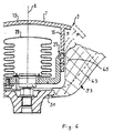
- the hub pot is made of the skeleton of the steering wheel formed from the hub that forms the bottom 51, and the Skeleton of the spokes which are attached to the hub and which are circumferential form not closed side wall 53.
- the side surface 9 lies on the skeleton of the spokes, i.e. on the side wall 53 at.
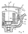
- FIG. 5 corresponds essentially to Figure 4, but that Skeleton 61 of the spokes has a foam surround 63 with a radially inward extending projection 65 as a stop for the outer peripheral wall 15 Has.
- the skeleton is located Spoke outside the cutting plane.
- the skeleton is covered with foam 63 provided the hub shell in the circumferential direction there is a closed form.
- the protrusion 65 on which the peripheral wall 15 strikes, lies between two spokes.
- a rib 71 secures the peripheral wall 15.
Landscapes
- Engineering & Computer Science (AREA)
- Mechanical Engineering (AREA)
- Air Bags (AREA)
Abstract
Description
Claims (13)
- Fahrzeuginsassen-Rückhaltesystem,mit einem Gassack-Modul (3), welcheseine Vorderseite (7), eine Seitenfläche (9) und eine Rückseite (11) aufweist und fernereine topfförmige Modulabdeckung (13) mit einer ersten Umfangswand (15) undein Aufnahmegehäuse (17) mit einer zweiten Umfangswand (21) aufweist,wobei Modulabdeckung (13) und Aufnahmegehäuse (17) einen Raum (27) zur Unterbringung eines Gassacks (29) als Teil des Moduls (3) definieren undwobei die erste und die zweite Umfangswand (15, 21) durch eine Rastverbindung (23; 25) miteinander verbunden sind und wenigstens eine der Umfangswände (15, 21) die Seitenfläche (9) definiert,
gekennzeichnet durcheinen fahrzeugseitig befestigten Aufnahmekörper (5) für das Gassack-Modul (3) in Form eines Nabentopfes eines Fahrzeuglenkrads,wobei der Aufnahmekörper (5) so nahe an der Seitenfläche (9) angeordnet ist, daß er die seitlich äußere der beiden Umfangswände (15, 21) beim Öffnen des Gassack-Moduls (3) seitlich stützt und die Rastverbindung sichert. - Fahrzeuginsassen-Rückhaltesystem nach Anspruch 1, dadurch gekennzeichnet, daß die erste Umfangswand (15) die seitlich äußere ist.
- Fahrzeuginsassen-Rückhaltesystem nach Anspruch 1 oder 2 dadurch gekennzeichnet, daß die Modulabdeckung (7) aus Kunststoff und das Aufnahmegehäuse (17) aus Blech sind.
- Fahrzeuginsassen-Rückhaltesystem nach einem der vorhergehenden Ansprüche, dadurch gekennzeichnet, daß das Aufnahmegehäuse (17) seitlich in Ausnehmungen (43; 47) in der ersten Umfangswand (15) ragende Rasthaken (41; 45) aufweist.
- Fahrzeuginsassen-Rückhaltesystem nach einem der vorhergehenden Ansprüche, dadurch gekennzeichnet, daß der Aufnahmekörper (5) an der seitlich äußeren Umfangswand (15) im nicht entfalteten Zustand des Gassacks (29) anliegt.
- Fahrzeuginsassen-Rückhaltesystem nach einem der vorhergehenden Ansprüche, dadurch gekennzeichnet, daß sich der Aufnahmekörper (5) zur Vorderseite nach außen aufweitet.
- Fahrzeuginsassen-Rückhaltesystem nach einem der vorhergehenden Ansprüche, dadurch gekennzeichnet, daß der Nabentopf durch die Nabe und die Speichen gebildet ist und daß sich die äußere Umfangswand beim Öffnen des Gassackmoduls an Speichen abstützt.
- Fahrzeuginsassen-Rückhaltesystem nach Anspruch 7, dadurch gekennzeichnet, daß die Speichen ein Skelett aufweisen und sich die äußere Umfangswand beim Öffnen des Gassackmoduls am Skelett der Speichen abstützt.
- Fahrzeuginsassen-Rückhaltesystem nach Anspruch 7, dadurch gekennzeichnet, daß die Speichen eine Umschäumung aufweisen und sich die äußere Umfangswand beim Öffnen des Gassackmoduls an der Umschäumung abstützt.
- Fahrzeuginsassen-Rückhaltesystem nach Anspruch 9, dadurch gekennzeichnet, daß die Umschäumung einen sich zur äußeren Umfangswand erstreckenden Vorsprung als Anschlag für die äußere Umfangswand hat.
- Fahrzeuginsassen-Rückhaltesystem nach Anspruch 9, dadurch gekennzeichnet, daß die Umschäumung dem Nabentopf eine in Umfangsrichtung geschlossene Gestalt gibt.
- Fahrzeuginsassen-Rückhaltesystem nach Anspruch 7, dadurch gekennzeichnet, daß der Nabentopf aus einem Boden und einer Seitenwand besteht und der Boden durch die Naben des Lenkrads und die Umfangswand durch eine an der Nabe befestigtes Kunststoffschale gebildet ist, an der sich die Umfangswand beim Öffnen des Gassackmoduls abstützt.
- Fahrzeuginsassen-Rückhaltesystem nach einem der vorhergehenden Ansprüche, dadurch gekennzeichnet, daß der Aufnahmekörper ein Aufnahmeblech oder Befestigungsblech für die Armaturentafel oder ein umgeformtes Gestell eines Fahrzeugsitzes ist.
Applications Claiming Priority (2)
| Application Number | Priority Date | Filing Date | Title |
|---|---|---|---|
| DE29921857U DE29921857U1 (de) | 1999-12-13 | 1999-12-13 | Fahrzeuginsassen-Rückhaltesystem |
| DE29921857U | 1999-12-13 |
Publications (3)
| Publication Number | Publication Date |
|---|---|
| EP1108625A2 true EP1108625A2 (de) | 2001-06-20 |
| EP1108625A3 EP1108625A3 (de) | 2004-01-07 |
| EP1108625B1 EP1108625B1 (de) | 2005-10-26 |
Family
ID=8082875
Family Applications (1)
| Application Number | Title | Priority Date | Filing Date |
|---|---|---|---|
| EP00126573A Expired - Lifetime EP1108625B1 (de) | 1999-12-13 | 2000-12-12 | Gassack-Modul mit Rastverbindung und nabentopfförmigem Aufnahmekörper |
Country Status (4)
| Country | Link |
|---|---|
| US (1) | US20010005075A1 (de) |
| EP (1) | EP1108625B1 (de) |
| DE (2) | DE29921857U1 (de) |
| ES (1) | ES2250065T3 (de) |
Cited By (1)
| Publication number | Priority date | Publication date | Assignee | Title |
|---|---|---|---|---|
| US11479199B2 (en) * | 2020-08-18 | 2022-10-25 | Autoliv Development Ab | Vehicle steering wheel comprising a steering wheel cladding and a safety module |
Families Citing this family (6)
| Publication number | Priority date | Publication date | Assignee | Title |
|---|---|---|---|---|
| DE10157440A1 (de) * | 2001-11-23 | 2003-06-12 | Breed Automotive Tech | Rasteinrichtung für ein Airbagmodul |
| US6783150B2 (en) * | 2002-09-30 | 2004-08-31 | Trw Vehicle Safety Systems Inc. | Snap together mounting of an air bag module and a vehicle steering wheel |
| US10295898B2 (en) | 2016-06-17 | 2019-05-21 | Moonlite World Inc. | Image projection device |
| US10571793B2 (en) * | 2016-06-17 | 2020-02-25 | Moonlite World Inc. | Image projection device |
| WO2018213501A1 (en) * | 2017-05-16 | 2018-11-22 | Performance Designed Products Llc | Smart user input devices, and systems and methods for monitoring such smart user input devices |
| US12377808B1 (en) * | 2024-10-16 | 2025-08-05 | Faurecia Interior Systems, Inc. | Vehicle interior panel having an expandable airbag chute |
Family Cites Families (10)
| Publication number | Priority date | Publication date | Assignee | Title |
|---|---|---|---|---|
| US5354093A (en) * | 1993-04-05 | 1994-10-11 | General Motors Corporation | Air bag module having integral cover attachment |
| US5505483A (en) * | 1993-04-28 | 1996-04-09 | Nippondenso Co., Ltd. | Airbag safety module for vehicle |
| US5460400A (en) * | 1994-05-20 | 1995-10-24 | Takata, Inc. | Passenger-side air bag module with improved assembly features |
| GB2290268B (en) * | 1994-06-07 | 1998-02-18 | Autoliv Dev | Improvements in or relating to a safety arrangement |
| DE4430588C2 (de) * | 1994-08-19 | 1999-02-25 | Petri Ag | Gassack (Airbag)-System für Kraftfahrzeuge |
| JPH08295199A (ja) | 1995-03-02 | 1996-11-12 | Nippondenso Co Ltd | エアバッグ装置 |
| JPH09142242A (ja) | 1995-11-27 | 1997-06-03 | Toyoda Gosei Co Ltd | 助手席用エアバッグ装置 |
| DE19730837A1 (de) * | 1997-07-18 | 1999-01-21 | Opel Adam Ag | Elastische Abdeckung für eine Airbag-Einrichtung |
| JPH11268602A (ja) | 1998-03-20 | 1999-10-05 | Toyoda Gosei Co Ltd | エアバッグ装置 |
| DE29816568U1 (de) | 1998-09-15 | 1998-11-05 | TRW Automotive Safety Systems GmbH, 63743 Aschaffenburg | Airbag-Modul für Kraftfahrzeuglenkräder |
-
1999
- 1999-12-13 DE DE29921857U patent/DE29921857U1/de not_active Expired - Lifetime
-
2000
- 2000-12-12 ES ES00126573T patent/ES2250065T3/es not_active Expired - Lifetime
- 2000-12-12 EP EP00126573A patent/EP1108625B1/de not_active Expired - Lifetime
- 2000-12-12 DE DE50011432T patent/DE50011432D1/de not_active Expired - Fee Related
- 2000-12-13 US US09/735,449 patent/US20010005075A1/en not_active Abandoned
Non-Patent Citations (1)
| Title |
|---|
| None |
Cited By (1)
| Publication number | Priority date | Publication date | Assignee | Title |
|---|---|---|---|---|
| US11479199B2 (en) * | 2020-08-18 | 2022-10-25 | Autoliv Development Ab | Vehicle steering wheel comprising a steering wheel cladding and a safety module |
Also Published As
| Publication number | Publication date |
|---|---|
| US20010005075A1 (en) | 2001-06-28 |
| DE50011432D1 (de) | 2005-12-01 |
| ES2250065T3 (es) | 2006-04-16 |
| EP1108625B1 (de) | 2005-10-26 |
| DE29921857U1 (de) | 2000-04-20 |
| EP1108625A3 (de) | 2004-01-07 |
Similar Documents
| Publication | Publication Date | Title |
|---|---|---|
| EP1288084B1 (de) | Gassackmodul | |
| DE102011010255B4 (de) | Instrumententafel | |
| EP1571048A2 (de) | Gassack-Modul, insbesondere für einen Knie-Gassack | |
| EP1068095A1 (de) | Haltegriffkonsole und baugruppe aus haltegriffkonsole und kopf-seitengassack-modul | |
| DE19641641A1 (de) | Airbagmodul mit vereinfachter Kissenbefestigung | |
| EP1108625B1 (de) | Gassack-Modul mit Rastverbindung und nabentopfförmigem Aufnahmekörper | |
| DE102010006358A1 (de) | Gassackmodul | |
| EP1324900B1 (de) | Gehäuse für einen aufblasbaren gassack eines kraftfahrzeuges | |
| DE19911930B4 (de) | Airbagmodul | |
| DE69615701T2 (de) | Luftsackmodul | |
| EP1426248B1 (de) | Gassackmodul | |
| EP1167123B1 (de) | Emblem für Gassackmodulabdeckung und Gassackmodul | |
| EP1452404B1 (de) | Gassackmodul für Lenkrad | |
| EP0618110B1 (de) | Armaturentafel mit Beifahrer-Airbag | |
| EP1251045B1 (de) | Gassackmodul | |
| DE102020115031A1 (de) | Lenkrad, welches ein Gassackmodul aufweist | |
| DE4330439C2 (de) | Formsteifes Verkleidungsteil für einen Fahrzeugaufbau | |
| EP0983913B1 (de) | Luftsack und Luftsackbefestigung | |
| EP1024061A2 (de) | Verbindung zwischen Generatorträger und Abdeckkappe in einem Airbagmodul | |
| EP1060957B1 (de) | Baueinheit für ein Gassack-Modul und Gassack-Modul | |
| DE10141461B4 (de) | Anordnung eines Seiten-Airbag-Moduls an einen Kraftfahrzeugsitz | |
| EP1452405A1 (de) | Gassackmodul | |
| DE10317335B4 (de) | Airbagvorrichtung | |
| DE29612556U1 (de) | Gassack-Modul | |
| DE10157043A1 (de) | Mittel zur Befestigung eines Airbagmoduls in einem Kraftfahrzeug |
Legal Events
| Date | Code | Title | Description |
|---|---|---|---|
| PUAI | Public reference made under article 153(3) epc to a published international application that has entered the european phase |
Free format text: ORIGINAL CODE: 0009012 |
|
| AK | Designated contracting states |
Kind code of ref document: A2 Designated state(s): AT BE CH CY DE DK ES FI FR GB GR IE IT LI LU MC NL PT SE TR |
|
| AX | Request for extension of the european patent |
Free format text: AL;LT;LV;MK;RO;SI |
|
| PUAL | Search report despatched |
Free format text: ORIGINAL CODE: 0009013 |
|
| AK | Designated contracting states |
Kind code of ref document: A3 Designated state(s): AT BE CH CY DE DK ES FI FR GB GR IE IT LI LU MC NL PT SE TR |
|
| AX | Request for extension of the european patent |
Extension state: AL LT LV MK RO SI |
|
| 17P | Request for examination filed |
Effective date: 20040621 |
|
| 17Q | First examination report despatched |
Effective date: 20040803 |
|
| AKX | Designation fees paid |
Designated state(s): DE ES FR GB IT |
|
| GRAP | Despatch of communication of intention to grant a patent |
Free format text: ORIGINAL CODE: EPIDOSNIGR1 |
|
| GRAS | Grant fee paid |
Free format text: ORIGINAL CODE: EPIDOSNIGR3 |
|
| GRAA | (expected) grant |
Free format text: ORIGINAL CODE: 0009210 |
|
| RAP1 | Party data changed (applicant data changed or rights of an application transferred) |
Owner name: TRW AUTOMOTIVE SAFETY SYSTEMS GMBH |
|
| AK | Designated contracting states |
Kind code of ref document: B1 Designated state(s): DE ES FR GB IT |
|
| PG25 | Lapsed in a contracting state [announced via postgrant information from national office to epo] |
Ref country code: GB Free format text: LAPSE BECAUSE OF FAILURE TO SUBMIT A TRANSLATION OF THE DESCRIPTION OR TO PAY THE FEE WITHIN THE PRESCRIBED TIME-LIMIT Effective date: 20051026 |
|
| REG | Reference to a national code |
Ref country code: GB Ref legal event code: FG4D Free format text: NOT ENGLISH |
|
| REF | Corresponds to: |
Ref document number: 50011432 Country of ref document: DE Date of ref document: 20051201 Kind code of ref document: P |
|
| REG | Reference to a national code |
Ref country code: ES Ref legal event code: FG2A Ref document number: 2250065 Country of ref document: ES Kind code of ref document: T3 |
|
| GBV | Gb: ep patent (uk) treated as always having been void in accordance with gb section 77(7)/1977 [no translation filed] |
Effective date: 20051026 |
|
| ET | Fr: translation filed | ||
| PLBE | No opposition filed within time limit |
Free format text: ORIGINAL CODE: 0009261 |
|
| STAA | Information on the status of an ep patent application or granted ep patent |
Free format text: STATUS: NO OPPOSITION FILED WITHIN TIME LIMIT |
|
| 26N | No opposition filed |
Effective date: 20060727 |
|
| PGFP | Annual fee paid to national office [announced via postgrant information from national office to epo] |
Ref country code: FR Payment date: 20061201 Year of fee payment: 7 |
|
| PGFP | Annual fee paid to national office [announced via postgrant information from national office to epo] |
Ref country code: ES Payment date: 20061220 Year of fee payment: 7 |
|
| PGFP | Annual fee paid to national office [announced via postgrant information from national office to epo] |
Ref country code: DE Payment date: 20061229 Year of fee payment: 7 |
|
| PGFP | Annual fee paid to national office [announced via postgrant information from national office to epo] |
Ref country code: IT Payment date: 20071217 Year of fee payment: 8 |
|
| PG25 | Lapsed in a contracting state [announced via postgrant information from national office to epo] |
Ref country code: DE Free format text: LAPSE BECAUSE OF NON-PAYMENT OF DUE FEES Effective date: 20080701 |
|
| PGFP | Annual fee paid to national office [announced via postgrant information from national office to epo] |
Ref country code: GB Payment date: 20051209 Year of fee payment: 6 |
|
| REG | Reference to a national code |
Ref country code: FR Ref legal event code: ST Effective date: 20081020 |
|
| REG | Reference to a national code |
Ref country code: ES Ref legal event code: FD2A Effective date: 20071213 |
|
| PG25 | Lapsed in a contracting state [announced via postgrant information from national office to epo] |
Ref country code: FR Free format text: LAPSE BECAUSE OF NON-PAYMENT OF DUE FEES Effective date: 20071231 Ref country code: ES Free format text: LAPSE BECAUSE OF NON-PAYMENT OF DUE FEES Effective date: 20071213 |
|
| PG25 | Lapsed in a contracting state [announced via postgrant information from national office to epo] |
Ref country code: IT Free format text: LAPSE BECAUSE OF NON-PAYMENT OF DUE FEES Effective date: 20081212 |