EP1452404B1 - Gassackmodul für Lenkrad - Google Patents
Gassackmodul für Lenkrad Download PDFInfo
- Publication number
- EP1452404B1 EP1452404B1 EP03028731A EP03028731A EP1452404B1 EP 1452404 B1 EP1452404 B1 EP 1452404B1 EP 03028731 A EP03028731 A EP 03028731A EP 03028731 A EP03028731 A EP 03028731A EP 1452404 B1 EP1452404 B1 EP 1452404B1
- Authority
- EP
- European Patent Office
- Prior art keywords
- fastening elements
- gas bag
- module housing
- generator
- gas
- Prior art date
- Legal status (The legal status is an assumption and is not a legal conclusion. Google has not performed a legal analysis and makes no representation as to the accuracy of the status listed.)
- Expired - Fee Related
Links
Images

Classifications
-
- B—PERFORMING OPERATIONS; TRANSPORTING
- B60—VEHICLES IN GENERAL
- B60R—VEHICLES, VEHICLE FITTINGS, OR VEHICLE PARTS, NOT OTHERWISE PROVIDED FOR
- B60R21/00—Arrangements or fittings on vehicles for protecting or preventing injuries to occupants or pedestrians in case of accidents or other traffic risks
- B60R21/02—Occupant safety arrangements or fittings, e.g. crash pads
- B60R21/16—Inflatable occupant restraints or confinements designed to inflate upon impact or impending impact, e.g. air bags
- B60R21/20—Arrangements for storing inflatable members in their non-use or deflated condition; Arrangement or mounting of air bag modules or components
- B60R21/217—Inflation fluid source retainers, e.g. reaction canisters; Connection of bags, covers, diffusers or inflation fluid sources therewith or together
-
- B—PERFORMING OPERATIONS; TRANSPORTING
- B60—VEHICLES IN GENERAL
- B60R—VEHICLES, VEHICLE FITTINGS, OR VEHICLE PARTS, NOT OTHERWISE PROVIDED FOR
- B60R21/00—Arrangements or fittings on vehicles for protecting or preventing injuries to occupants or pedestrians in case of accidents or other traffic risks
- B60R21/02—Occupant safety arrangements or fittings, e.g. crash pads
- B60R21/16—Inflatable occupant restraints or confinements designed to inflate upon impact or impending impact, e.g. air bags
- B60R21/20—Arrangements for storing inflatable members in their non-use or deflated condition; Arrangement or mounting of air bag modules or components
- B60R21/203—Arrangements for storing inflatable members in their non-use or deflated condition; Arrangement or mounting of air bag modules or components in steering wheels or steering columns
- B60R21/2035—Arrangements for storing inflatable members in their non-use or deflated condition; Arrangement or mounting of air bag modules or components in steering wheels or steering columns using modules containing inflator, bag and cover attachable to the steering wheel as a complete sub-unit
- B60R21/2037—Arrangements for storing inflatable members in their non-use or deflated condition; Arrangement or mounting of air bag modules or components in steering wheels or steering columns using modules containing inflator, bag and cover attachable to the steering wheel as a complete sub-unit the module or a major component thereof being yieldably mounted, e.g. for actuating the horn switch or for protecting the driver in a non-deployment situation
Definitions
- the invention relates to an airbag module with a gas generator and a module housing, wherein the gas generator has a generator flange.
- Racer modules have been part of the standard equipment of modern vehicles for several years. Considerations for cost-effectiveness require that the gas bag module can be mounted in as few work steps as possible and fastened to the vehicle. In the attachment of gas bag modules in steering wheels, therefore, an attachment over fittings for cost and time reasons is increasingly being replaced by the use of snap-in connections. These must be fast and easy to close at the same time and ensure a secure connection.
- US 2002/0109337 describes an airbag module with a gas generator and a module housing, wherein the gas generator has a generator flange, wherein on the generator support first, consisting of sheet metal, hook-shaped fastening elements for fastening the gas bag module to a steering wheel and second fastening elements for attachment of the gas generator are formed on the module housing ,
- DE 29 621 295 U describes an airbag module with a gas generator and a module housing wherein the gas generator is mounted in a generator carrier, wherein on the generator support first, consisting of sheet metal, hook-shaped fastening elements for attachment of the airbag module are formed on a steering wheel.
- the object of the invention is to improve an above-mentioned airbag module with respect to its mounting and attachment to the steering wheel. This object is achieved with the features of claim 1.
- This design makes it possible to attach the gas bag module via the gas generator on the steering wheel, for example by means of a latching connection, while at the same time with little effort, the gas generator can be fixed to the module housing.
- the generator flange which is usually a gas generator radially surrounding sheet metal ring, according to the invention is designed so that can be dispensed with further components for mounting the gas generator on the module housing and the module on the steering wheel.
- the attachment of the module to the steering wheel via the gas generator also has the advantage that the high forces occurring when igniting the gas generator can be transmitted directly to steering wheel-fixed components. By reducing the number of components, manufacturing time and manufacturing costs are reduced.
- the first and second fasteners are punched or cut out of sheet metal.
- the production of the generator flange can be made so that the first and second fastening elements are already manufactured in one piece with the sheet metal flange.
- the generator flange and the fasteners are punched or cut out of the initially flat sheet and later bent or reshaped into their final position and shape.
- the second fastening elements are formed as sheet metal sections and connected to the module housing by crimping.
- An embodiment of the invention provides that the second fastening elements are connected to the module housing via at least one securing clip.
- the closer to the generator portions of the first fastening elements may serve as second fastening elements, which acts on the securing clip and thus fixes the gas generator to the module housing.
- the second fastening elements may alternatively be formed as separate from the first fastening elements components.
- the second fastening elements are connected to the module housing by a press fit.
- z. B. a circumferentially completely surrounding the gas generator portion of the generator flange as a second fastener use.
- the generator flange can take on a further task by a blow-in mouth of a gas bag arranged in the module housing is fixed by the generator flange on the module housing, which allows the saving of an additional airbag retaining element.
- the gas bag is in this case clamped in a conventional manner between the generator flange, which serves as a gas bag holding element, and the module housing, wherein openings may be provided in the gas bag, which surround the inflation, through which the first and / or second fastening elements extend to the gas bag additionally to fix.
- An object of the invention is to secure the gas bag module to the steering wheel via the generator flange or, generally speaking, to a vehicle while simultaneously connecting the gas generator to the module housing via the generator flange.
- the module housing can in this case be designed as a shell which receives the gas generator and the gas bag, but it can also be, for example, a plate-shaped gas generator carrier or another component.
- FIGS. 1a and b show a steering wheel 10 with an airbag module 12, the airbag module 12 being inserted in the hub region of the steering wheel 10 and being fixed thereto.
- the gas bag module 12 has a cup-shaped module housing 14 with a bottom 15, a gas generator 16 and a folded, arranged in the module housing 14 airbag 18.
- the module housing 14 is closed in a known manner by a cover 20.
- a cup-shaped module housing 14 is shown, in which the gas bag 18 is received.
- the invention is readily applicable to other forms of module housing, such. B. flat generator support, transferable.
- the gas generator 16 in the case shown here is a cylindrical, cup-shaped gas generator, which is surrounded circumferentially by a radially projecting, consisting of a sheet generator flange 22.
- first fastening elements 24 which extend through openings 25 in the bottom 15 of the module housing 14 and engage in a fixedly connected to the steering wheel, but movable by a certain amount locking means 26 to fix the gas bag module 12 on the steering wheel 10.
- the locking means 26 is held by steering wheel firmly formed hooks 28.
- the hook-shaped first fastening elements 24 engage directly in complementary locking elements on the steering wheel 10.
- Several of these first fastening elements 24 are provided which surround the gas generator 16 circumferentially, preferably 3 to 5. The hooks of the first fastening elements 24 may point either in the same or in different directions.
- the gas bag module 12 is designed as a so-called floating horn module.
- the generator flange 22 has, in addition to the first fastening elements 24, a plurality of second fastening elements 30. In the embodiment illustrated in FIG. 1 a, these are designed as tabs cut free from the arms of the first fastening elements 24, which are bent in the direction of the gas generator 16 and embrace the bottom of the module housing 14 at the edge of the openings 25.
- the second fasteners 30 are fixedly secured to the module housing 14 in this case by crimping. The bent portions of the second fasteners 30 are after their attachment to the module housing 14 on the side facing the steering wheel 10 of the module housing 14.
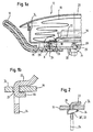
- FIG. 2 shows a further embodiment.
- the second fastening elements 30 ' are formed by recesses 32 in the arms of the first fastening elements 24.
- the inflator 16 is secured to the module housing 14 by a wedge-clamp connection with one or more wedge-shaped section members 34.
- the recess 32 is formed in the arm of one of the fastening elements 24, but it is also possible to provide the second fastening elements 30 'at a location spatially separate from the first fastening elements 24.
- the second fasteners 30 are formed by upper portions of the first fasteners 24. These are fixed to the underside of the module housing 14 by one or more correspondingly shaped, stamped securing clips 36 which facilitate movement of the inflator from the steering wheel 10.
- the securing clip has two deformed, sharp-edged flaps 50 whose edges press against the side surfaces of the fastener 30 ".
- the generator flange 22 also serves as a gas bag holding element at the same time.
- the edge 40 of a blowing mouth of the gas bag 18 is clamped between the generator flange 22 and the bottom of the module housing 14.
- the gas bag 18 may e.g. having the openings 25 of the module housing 14 corresponding openings through which pass through the first and / or second fastening elements 24, 30.
- the embodiments shown in FIGS. 2 and 3 can also have a generator flange 22 configured in this way.
- the second fastening element 30 is designed as a section of the generator flange, which is connected to the bottom 15 of the module housing 14, preferably to an edge of a module housing Opening, in which the gas generator is inserted, is connected via a press fit.
- the first and second fastening elements are not integrally connected to the generator flange, but formed as separate components and connected by gluing or welding firmly to the generator flange.
- the generator flange in turn may be integrally formed with the gas generator or a separate, permanently connected to this component.
Landscapes
- Engineering & Computer Science (AREA)
- Mechanical Engineering (AREA)
- Air Bags (AREA)
Description
- Die Erfindung betrifft ein Gassackmodul mit einem Gasgenerator und einem Modulgehäuse, wobei der Gasgenerator einen Generatorflansch aufweist.
- Fahrergassackmodule gehören seit einigen Jahren zur Serienausstattung moderner Fahrzeuge. Überlegungen zur Wirtschaftlichkeit fordern, das Gassackmodul in möglichst wenigen Arbeitsschritten montieren und am Fahrzeug befestigen zu können. Bei der Befestigung von Gassackmodulen in Lenkrädern wird daher eine Befestigung über Verschraubungen aus Kosten- und Zeitgründen immer mehr durch die Verwendung von Rastverbindungen ersetzt. Diese müssen gleichzeitig schnell und einfach schließbar sein und eine sichere Verbindung gewährleisten.
- US 2002/0109337 beschreibt ein Gassackmodul mit einem Gasgenerator und einem Modulgehäuse, wobei der Gasgenerator einen Generatorflansch aufweist, wobei am Generatorträger erste, aus Blech bestehende, hakenförmige Befestigungselemente zur Befestigung des Gassackmoduls an einem Lenkrad und zweite Befestigungselemente zur Befestigung des Gasgenerators am Modulgehäuse ausgebildet sind.
- DE 29 621 295 U beschreibt ein Gassackmodul mit einem Gasgenerator und einem Modulgehäuse wobei der Gasgenerator in einem Generatorträger befestigt ist, wobei am Generatorträger erste, aus Blech bestehende, hakenförmige Befestigungselemente zur Befestigung des Gassackmoduls an einem Lenkrad ausgebildet sind.
- Aufgabe der Erfindung ist es, ein obengenanntes Gassackmodul bezüglich seiner Montage und Befestigung am Lenkrad zu verbessern. Diese Aufgabe ist mit den Merkmalen des Anspruchs 1 gelöst. Diese Gestaltung erlaubt es, das Gassackmodul über den Gasgenerator am Lenkrad z.B. mittels einer Rastverbindung zu befestigen, während gleichzeitig mit wenig Aufwand der Gasgenerator am Modulgehäuse fixierbar ist. Der Generatorflansch, der gewöhnlich ein den Gasgenerator radial umgebender Blechring ist, ist erfindungsgemäß so ausgebildet, daß auf weitere Bauteile zur Befestigung des Gasgenerators am Modulgehäuse sowie des Moduls am Lenkrad verzichtet werden kann. Die Befestigung des Moduls am Lenkrad über den Gasgenerator hat auch den Vorteil, daß die beim Zünden des Gasgenerators auftretenden hohen Kräfte direkt an lenkradfeste Bauteile übertragen werden können. Durch die Reduktion der Zahl der Bauteile werden Fertigungszeit und Fertigungskosten reduziert.
- Bevorzugt sind die ersten und zweiten Befestigungselemente aus Blech ausgestanzt oder ausgeschnitten. Die Herstellung des Generatorflanschs kann so erfolgen, daß einstückig mit dem Blechflansch bereits die ersten und zweiten Befestigungselemente gefertigt werden. Hierzu werden der Generatorflansch sowie die Befestigungselemente aus dem zunächst flachen Blech ausgestanzt oder ausgeschnitten und erst später in ihre endgültige Position und Form gebogen oder umgeformt.
- Nach einer anderen bevorzugten Ausführungsform der Erfindung sind die zweiten Befestigungselemente als Blechabschnitte ausgebildet und mit dem Modulgehäuse durch Krimpen verbunden. Hierzu sind die am Generatorflansch ausgebildeten Abschnitte z.B. um den Rand einer Öffnung des Modulgehäuses umgebogen und an diesem durch Krimpen befestigt.
- Eine Ausführungsform der Erfindung sieht vor, daß die zweiten Befestigungselemente mit dem Modulgehäuse über wenigstens eine Sicherungsklammer verbunden sind. In diesem Fall können die näher zum Generator gelegenen Abschnitte der ersten Befestigungselemente als zweite Befestigungselemente dienen, an denen die Sicherungsklammer angreift und so den Gasgenerator am Modulgehäuse fixiert. Auch hier können die zweiten Befestigungselemente alternativ als von den ersten Befestigungselementen separate Bauteile ausgebildet sein.
- Nach einer weiteren bevorzugten Ausführungsform sind die zweiten Befestigungselemente mit dem Modulgehäuse durch eine Preßpassung verbunden. Hierzu läßt sich z. B. ein den Gasgenerator umfangsmäßig vollständig umgebender Abschnitt des Generatorflansches als zweites Befestigungselement nutzen.
- Der Generatorflansch kann noch eine weitere Aufgabe übernehmen, indem ein Einblasmund eines im Modulgehäuse angeordneten Gassacks durch den Generatorflansch am Modulgehäuse befestigt ist, was die Einsparung eines zusätzlichen Gassackhalteelements erlaubt. Der Gassack wird hierbei auf herkömmliche Weise zwischen dem Generatorflansch, der als Gassackhalteelement dient, sowie dem Modulgehäuse geklemmt, wobei im Gassack Öffnungen vorgesehen sein können, die den Einblasmund umgeben, durch die sich die ersten und/oder zweiten Befestigungselemente erstrecken, um den Gassack zusätzlich zu fixieren.
- Ein Ziel der Erfindung ist es, über den Generatorflansch das Gassackmodul am Lenkrad oder, allgemein gesprochen, an einem Fahrzeug zu befestigen, während gleichzeitig über den Generatorflansch der Gasgenerator mit dem Modulgehäuse verbunden wird. Das Modulgehäuse kann hierbei als Schale ausgebildet sein, die den Gasgenerator und den Gassack aufnimmt, es kann sich aber auch z.B. um einen plattenförmigen Gasgeneratorträger oder ein anderes Bauteil handeln.
- Weitere Merkmale und Vorteile der Erfindung ergeben sich aus der nachfolgenden Beschreibung mehrerer Ausführungsbeispiele in Verbindung mit den beigefügten Zeichnungen. In diesen zeigen:
- Figur 1a eine teilgeschnittene Ansicht eines erfindungsgemäßen Gassackmoduls gemäß einer ersten Ausführungsform;
- Figur 1b eine vergrößerte Ansicht des mit "X" bezeichneten Details des Gassackmoduls aus Figur 1;
- Figur 2 das mit "X" bezeichnete Detail des Gassackmoduls aus Figur 1 gemäß einer zweiten Ausführungsform der Erfindung;
- Figur 3 das mit "X" bezeichnete Detail des Gassackmoduls aus Figur 1 gemäß einer dritten Ausführungsform der Erfindung;
- Figur 4 einen Schnitt durch die Befestigungselemente längs der Linie IV-IV in Figur 3; und
- Figur 5 einen Schnitt durch das Befestigungselement und den Boden des Modulgehäuses gemäß einer weiteren Ausführungsform.
- In den Figuren 1a und b ist ein Lenkrad 10 mit einem Gassackmodul 12 gezeigt, wobei das Gassackmodul 12 in dem Nabenbereich des Lenkrads 10 eingesetzt und an diesem fixiert ist.
- Das Gassackmodul 12 weist ein topfförmiges Modulgehäuse 14 mit einem Boden 15 auf, einen Gasgenerator 16 sowie einen gefalteten, im Modulgehäuse 14 angeordneten Gassack 18. Das Modulgehäuse 14 ist auf bekannte Weise durch eine Abdeckung 20 verschlossen. Hier ist ein schalenförmiges Modulgehäuse 14 gezeigt, in dem der Gassack 18 aufgenommen ist. Die Erfindung ist jedoch auch ohne weiteres auf andere Formen des Modulgehäuses, wie z. B. flache Generatorträger, übertragbar.
- Der Gasgenerator 16 ist im hier gezeigten Fall ein zylindrischer, topfförmiger Gasgenerator, der umfangsmäßig von einem radial abstehenden, aus einem Blech bestehenden Generatorflansch 22 umgeben ist.
- Am Generatorflansch 22 sind streifenförmige seitliche Fortsätze axial in Richtung Boden 15 gebogen. Diese haben hakenförmige erste Befestigungselemente 24, die sich durch Öffnungen 25 im Boden 15 des Modulgehäuses 14 erstrecken und in ein fest mit dem Lenkrad verbundenes, aber um ein gewisses Spiel bewegbares Arretierungsmittel 26 eingreifen, um das Gassackmodul 12 am Lenkrad 10 zu fixieren. In der hier dargestellten Ausführungsform ist das Arretierungsmittel 26 von lenkradfest ausgebildeten Haken 28 gehalten. Selbstverständlich sind auch Ausführungsformen denkbar, in denen die hakenförmigen ersten Befestigungselemente 24 direkt in komplementäre Rastelemente am Lenkrad 10 eingreifen. Es sind mehrere dieser ersten Befestigungselemente 24 vorgesehen, die den Gasgenerator 16 umfangsmäßig umgeben, bevorzugt 3 bis 5. Die Haken der ersten Befestigungselemente 24 können entweder in die gleiche oder in verschiedene Richtungen weisen.
- In den hier gezeigten Beispielen ist das Gassackmodul 12 als sogenanntes Floating-Horn-Modul ausgebildet.
- Der Generatorflansch 22 weist zusätzlich zu den ersten Befestigungselementen 24 mehrere zweite Befestigungselemente 30 auf. In der in Figur la dargestellten Ausführungsform sind diese als aus den Armen der ersten Befestigungselemente 24 freigeschnittene Laschen ausgebildet, die in Richtung zum Gasgenerator 16 hin umgebogen sind und am Rand der Öffnungen 25 den Boden des Modulgehäuses 14 umgreifen. Die zweiten Befestigungselemente 30 sind am Modulgehäuse 14 in diesem Fall durch Krimpen fest befestigt. Die umgebogenen Abschnitte der zweiten Befestigungselemente 30 liegen nach deren Befestigung am Modulgehäuse 14 an der zum Lenkrad 10 gerichteten Seite des Modulgehäuses 14 an.
- Es ist auch denkbar, die zweiten Befestigungselemente 30 an einer anderen Stelle des Umfangs des Generatorflansches 22 anzuordnen als die ersten Befestigungselemente 24.
- In Figur 2 ist eine weitere Ausführungsform dargestellt. Hier sind die zweiten Befestigungselemente 30' durch Ausnehmungen 32 in den Armen der ersten Befestigungselemente 24 gebildet. Der Gasgenerator 16 wird durch eine Keil-Klemmverbindung mit einem oder mehreren einen keilförmigen Abschnitt aufweisenden Bauteilen 34 am Modulgehäuse 14 befestigt. Wie in Figur 2 angedeutet, ist die Ausnehmung 32 im Arm eines der Befestigungselemente 24 ausgebildet, es ist jedoch auch möglich, die zweiten Befestigungselemente 30' an einer räumlich von der ersten Befestigungselementen 24 getrennten Stelle vorzusehen.
- Bei der in den Figuren 3 und 4 gezeigten Ausführungsform sind die zweiten Befestigungselemente 30" durch obere Abschnitte der ersten Befestigungselemente 24 gebildet. Diese werden auf der Unterseite des Modulgehäuses 14 durch eine oder mehrere entsprechend geformte, gestanzte Sicherungsklammern 36 fixiert, die eine Bewegung des Gasgenerators vom Lenkrad 10 weg verhindern. Die Sicherungsklammer hat zwei umgeformte, scharfkantige Laschen 50, deren Ränder gegen die Seitenflächen des Befestigungselements 30" drücken.
- Der Generatorflansch 22 dient auch gleichzeitig als Gassackhalteelement. Der Rand 40 eines Einblasmunds des Gassacks 18 ist zwischen dem Generatorflansch 22 und dem Boden des Modulgehäuses 14 geklemmt. Der Gassack 18 kann z.B. mit den Öffnungen 25 des Modulgehäuses 14 korrespondierende Öffnungen aufweisen, durch die die ersten und/oder zweiten Befestigungselemente 24, 30 hindurchgreifen. Auch die in den Figuren 2 und 3 gezeigten Ausführungsformen können einen derart ausgebildeten Generatorflansch 22 aufweisen.
- In der in Figur 5 gezeigten Ausführungsform der Erfindung ist das zweite Befestigungselement 30" als ein Abschnitt des Generatorflansches ausgebildet, der mit dem Boden 15 des Modulgehäuses 14, bevorzugt mit einem Rand einer Öffnung, in die der Gasgenerator eingesetzt ist, über eine Preßpassung verbunden ist.
- In einer anderen möglichen Ausführungsform der Erfindung sind die ersten bzw. zweiten Befestigungselemente nicht einstückig mit dem Generatorflansch verbunden, sondern als separate Bauteile ausgebildet und durch Kleben oder Schweißen fest mit dem Generatorflansch verbunden. Der Generatorflansch wiederum kann einstückig mit dem Gasgenerator ausgebildet oder ein separates, fest mit diesem verbundenes Bauteil sein.
Claims (9)
- Gassackmodul mit einem Gasgenerator (16) und einem Modulgehäuse (14),
wobei der Gasgenerator (16) einen Generatorflansch (22) aufweist, an dem erste, aus Blech bestehende, hakenförmige Befestigungselemente (24) zur Befestigung des Gassackmoduls (12) an einem Lenkrad (10)
und zweite Befestigungselemente (30; 30'; 30") zur Befestigung des Gasgenerators (16) am Modulgehäuse (14) ausgebildet sind, wobei die zweiten Befestigungselemente (30; 30'; 30") an den ersten Befestigungselementen (24) ausgebildet sind. - Gassackmodul nach Anspruch 1, dadurch gekennzeichnet, daß die ersten und zweiten Befestigungselemente (24; 30; 30'; 30") aus Blech ausgestanzt oder ausgeschnitten sind.
- Gassackmodul nach Anspruch 1, dadurch gekennzeichnet, daß die zweiten Befestigungselemente (30') jeweils durch eine Aussparung (32) in den ersten Befestigungselementen (24) gebildet sind.
- Gassackmodul nach einem der vorhergehenden Ansprüche, dadurch gekennzeichnet, daß die zweiten Befestigungselemente (30') mit dem Modulgehäuse (14) durch eine Keil-Klemmverbindung (32, 34) verbunden sind.
- Gassackmodul nach einem der Ansprüche 1 bis 2, dadurch gekennzeichnet, daß die zweiten Befestigungselemente (30) als Blechabschnitte ausgebildet und mit dem Modulgehäuse (14) durch Krimpen verbunden sind.
- Gassackmodul nach einem der Ansprüche 1 bis 2, dadurch gekennzeichnet, daß die zweiten Befestigungselemente (30") mit dem Modulgehäuse (14) über wenigstens eine Sicherungsklammer (36) verbunden sind.
- Gassackmodul nach einem der Ansprüche 1 bis 2, dadurch gekennzeichnet, daß die zweiten Befestigungselemente mit dem Modulgehäuse durch eine Preßpassung verbunden sind.
- Gassackmodul nach einem der vorhergehenden Ansprüche dadurch gekennzeichnet, daß ein Einblasmund eines im Modulgehäuse (14) angeordneten Gassacks (18) durch den Generatorflansch (22) am Modulgehäuse (14) befestigt ist.
- Gassackmodul nach einem der vorhergehenden Ansprüche, dadurch gekennzeichnet, daß die Befestigungselemente (24, 30, 30', 30") an axial in Richtung Boden (15) des Modulgehäuses umgebogenen streifenförmigen seitlichen Fortsätzen des Generatorflansches vorgesehen sind.
Applications Claiming Priority (2)
| Application Number | Priority Date | Filing Date | Title |
|---|---|---|---|
| DE20303303U | 2003-02-28 | ||
| DE20303303U DE20303303U1 (de) | 2003-02-28 | 2003-02-28 | Gassackmodul |
Publications (2)
| Publication Number | Publication Date |
|---|---|
| EP1452404A1 EP1452404A1 (de) | 2004-09-01 |
| EP1452404B1 true EP1452404B1 (de) | 2006-04-26 |
Family
ID=7980457
Family Applications (1)
| Application Number | Title | Priority Date | Filing Date |
|---|---|---|---|
| EP03028731A Expired - Fee Related EP1452404B1 (de) | 2003-02-28 | 2003-12-12 | Gassackmodul für Lenkrad |
Country Status (4)
| Country | Link |
|---|---|
| US (1) | US7100940B2 (de) |
| EP (1) | EP1452404B1 (de) |
| DE (2) | DE20303303U1 (de) |
| ES (1) | ES2262938T3 (de) |
Families Citing this family (9)
| Publication number | Priority date | Publication date | Assignee | Title |
|---|---|---|---|---|
| DE50303444D1 (de) * | 2002-08-27 | 2006-06-29 | Trw Automotive Safety Sys Gmbh | Gassackmodul |
| US20050046153A1 (en) * | 2003-08-27 | 2005-03-03 | Depottey Timothy A. | Airbag inflator mounting apparatus and method |
| WO2007091928A1 (en) * | 2006-02-08 | 2007-08-16 | Autoliv Development Ab | An air-bag module |
| DE102006058491B4 (de) * | 2006-10-02 | 2018-03-15 | Johnson Controls Interiors Gmbh & Co. Kg | Mehrteiliges Fahrzeugausstattungsteil und Verbindungsverfahren |
| KR100844560B1 (ko) * | 2006-11-16 | 2008-07-08 | 현대자동차주식회사 | 에어백 장치 |
| JP5117838B2 (ja) * | 2007-12-13 | 2013-01-16 | タカタ株式会社 | エアバッグ装置 |
| DE102009030601A1 (de) * | 2009-06-26 | 2011-03-03 | Trw Automotive Safety Systems Gmbh | Baugruppe und Gassackmodul |
| DE102011082279A1 (de) * | 2011-09-07 | 2013-03-07 | TAKATA Aktiengesellschaft | Gasgeneratorträger für ein Gassackmodul eines Fahrzeuginsassen-Rückhaltesystems und Verfahren zum Herstellen eines Gassackmoduls |
| JP6459523B2 (ja) * | 2015-01-08 | 2019-01-30 | Joyson Safety Systems Japan株式会社 | エアバッグ装置 |
Family Cites Families (13)
| Publication number | Priority date | Publication date | Assignee | Title |
|---|---|---|---|---|
| US109337A (en) * | 1870-11-15 | Improvement in screw-piles | ||
| US5678850A (en) * | 1996-08-09 | 1997-10-21 | Morton International, Inc. | Cover mounting arrangement for airbag module |
| JPH1086781A (ja) | 1996-09-17 | 1998-04-07 | Denso Corp | エアバッグ装置 |
| US5762359A (en) * | 1996-10-02 | 1998-06-09 | General Motors Corporation | Air bag module and steering wheel assembly |
| DE29621295U1 (de) * | 1996-11-27 | 1997-02-06 | Petri Ag | Vorrichtung zur Befestigung eines Airbagmoduls im Lenkrad |
| JP2001341605A (ja) * | 2000-05-31 | 2001-12-11 | Takata Corp | エアバッグ装置 |
| US6695343B1 (en) * | 2000-11-20 | 2004-02-24 | Trw Vehicle Safety Systems Inc. | Snap-in air bag module |
| DE20021532U1 (de) * | 2000-12-20 | 2001-04-26 | Trw Automotive Safety Sys Gmbh | Fahrzeuglenkrad |
| US6565113B2 (en) * | 2001-02-09 | 2003-05-20 | Delphi Technologies, Inc. | Air bag module |
| US6899352B2 (en) * | 2001-09-28 | 2005-05-31 | Toyoda Gosei Co., Ltd | Airbag device |
| US6752415B2 (en) * | 2001-10-05 | 2004-06-22 | Autoliv Asp, Inc. | Airbag module Z-height control tab |
| JP2005313713A (ja) * | 2004-04-27 | 2005-11-10 | Takata Corp | ステアリング装置 |
| DE602004014253D1 (de) * | 2004-05-10 | 2008-07-17 | Key Safety Systems Inc | Baugruppe mit einem Lenkrad und einem Gassackmodul |
-
2003
- 2003-02-28 DE DE20303303U patent/DE20303303U1/de not_active Expired - Lifetime
- 2003-12-12 DE DE50303105T patent/DE50303105D1/de not_active Expired - Fee Related
- 2003-12-12 EP EP03028731A patent/EP1452404B1/de not_active Expired - Fee Related
- 2003-12-12 ES ES03028731T patent/ES2262938T3/es not_active Expired - Lifetime
-
2004
- 2004-01-20 US US10/760,435 patent/US7100940B2/en not_active Expired - Fee Related
Also Published As
| Publication number | Publication date |
|---|---|
| US20040169354A1 (en) | 2004-09-02 |
| DE50303105D1 (de) | 2006-06-01 |
| DE20303303U1 (de) | 2003-07-03 |
| EP1452404A1 (de) | 2004-09-01 |
| US7100940B2 (en) | 2006-09-05 |
| ES2262938T3 (es) | 2006-12-01 |
Similar Documents
| Publication | Publication Date | Title |
|---|---|---|
| DE69910181T2 (de) | Airbagmodul-mechanismus und verfahren zur montage eines airbags | |
| EP1216895B1 (de) | Haltevorrichtung | |
| DE102009040303B4 (de) | Lenkrad mit Airbagvorrichtung | |
| EP1721788B1 (de) | Befestigungselement zum Anbringen und Rückhalten eines Airbags an einer Fahrzeugkarosserie | |
| DE60102363T2 (de) | Schnappbefestigung für fahrer-airbagmodul | |
| EP2121390B1 (de) | Folienplakette für eine airbagabdeckung | |
| EP3209525B1 (de) | Gassackmodul, diffusor für ein gassackmodul sowie fahrzeuginsassen-sicherungssystem | |
| DE60008901T2 (de) | Montiermechanismus für ein aufblabares rückhaltesystem | |
| DE202005009002U1 (de) | Modulbaugruppe für eine Airbageinrichtung zum Schutz von Insassen eines Kraftfahrzeugs | |
| EP3842297B1 (de) | Lenkungsbaugruppe sowie verfahren zur montage eines gassackmoduls an einem lenkrad zur bildung einer solchen lenkungsbaugruppe | |
| EP1452404B1 (de) | Gassackmodul für Lenkrad | |
| EP2509830B1 (de) | Fahrzeuglenkrad | |
| WO2012072152A1 (de) | Befestigungsvorrichtung und befestigungsbaugruppe zur befestigung eines gasgenerators und fahrzeuginsassenrückhaltesystem | |
| DE19929924A1 (de) | Schweißbolzen | |
| EP1426248B1 (de) | Gassackmodul | |
| EP1324900B1 (de) | Gehäuse für einen aufblasbaren gassack eines kraftfahrzeuges | |
| DE19911930B4 (de) | Airbagmodul | |
| EP2419305B1 (de) | Gassackanordnung für ein fahrzeuginsassen-rückhaltesystem und verfahren zum herstellen einer gassackanordnung | |
| EP1167123B1 (de) | Emblem für Gassackmodulabdeckung und Gassackmodul | |
| EP1024061A2 (de) | Verbindung zwischen Generatorträger und Abdeckkappe in einem Airbagmodul | |
| EP0983913B1 (de) | Luftsack und Luftsackbefestigung | |
| DE102017114301A1 (de) | Schwingungstilgerring sowie gassackmodul mit einem solchen schwingungstilgerring | |
| EP1251045B1 (de) | Gassackmodul | |
| DE19626686B4 (de) | Verfahren zur Befestigung eines Reibelementes | |
| EP1533199A1 (de) | Gassackmodul |
Legal Events
| Date | Code | Title | Description |
|---|---|---|---|
| PUAI | Public reference made under article 153(3) epc to a published international application that has entered the european phase |
Free format text: ORIGINAL CODE: 0009012 |
|
| AK | Designated contracting states |
Kind code of ref document: A1 Designated state(s): AT BE BG CH CY CZ DE DK EE ES FI FR GB GR HU IE IT LI LU MC NL PT RO SE SI SK TR |
|
| AX | Request for extension of the european patent |
Extension state: AL LT LV MK |
|
| 17P | Request for examination filed |
Effective date: 20050209 |
|
| AKX | Designation fees paid |
Designated state(s): DE ES FR GB IT |
|
| 17Q | First examination report despatched |
Effective date: 20050411 |
|
| GRAP | Despatch of communication of intention to grant a patent |
Free format text: ORIGINAL CODE: EPIDOSNIGR1 |
|
| GRAS | Grant fee paid |
Free format text: ORIGINAL CODE: EPIDOSNIGR3 |
|
| GRAA | (expected) grant |
Free format text: ORIGINAL CODE: 0009210 |
|
| AK | Designated contracting states |
Kind code of ref document: B1 Designated state(s): DE ES FR GB IT |
|
| PG25 | Lapsed in a contracting state [announced via postgrant information from national office to epo] |
Ref country code: GB Free format text: LAPSE BECAUSE OF FAILURE TO SUBMIT A TRANSLATION OF THE DESCRIPTION OR TO PAY THE FEE WITHIN THE PRESCRIBED TIME-LIMIT Effective date: 20060426 |
|
| REG | Reference to a national code |
Ref country code: GB Ref legal event code: FG4D Free format text: NOT ENGLISH |
|
| REF | Corresponds to: |
Ref document number: 50303105 Country of ref document: DE Date of ref document: 20060601 Kind code of ref document: P |
|
| GBV | Gb: ep patent (uk) treated as always having been void in accordance with gb section 77(7)/1977 [no translation filed] |
Effective date: 20060426 |
|
| ET | Fr: translation filed | ||
| REG | Reference to a national code |
Ref country code: ES Ref legal event code: FG2A Ref document number: 2262938 Country of ref document: ES Kind code of ref document: T3 |
|
| PGFP | Annual fee paid to national office [announced via postgrant information from national office to epo] |
Ref country code: IT Payment date: 20061231 Year of fee payment: 4 |
|
| PLBE | No opposition filed within time limit |
Free format text: ORIGINAL CODE: 0009261 |
|
| STAA | Information on the status of an ep patent application or granted ep patent |
Free format text: STATUS: NO OPPOSITION FILED WITHIN TIME LIMIT |
|
| 26N | No opposition filed |
Effective date: 20070129 |
|
| REG | Reference to a national code |
Ref country code: FR Ref legal event code: ST Effective date: 20070831 |
|
| REG | Reference to a national code |
Ref country code: ES Ref legal event code: FD2A Effective date: 20061213 |
|
| PG25 | Lapsed in a contracting state [announced via postgrant information from national office to epo] |
Ref country code: ES Free format text: LAPSE BECAUSE OF NON-PAYMENT OF DUE FEES Effective date: 20061213 Ref country code: FR Free format text: LAPSE BECAUSE OF NON-PAYMENT OF DUE FEES Effective date: 20070102 |
|
| PGFP | Annual fee paid to national office [announced via postgrant information from national office to epo] |
Ref country code: DE Payment date: 20081230 Year of fee payment: 6 |
|
| PG25 | Lapsed in a contracting state [announced via postgrant information from national office to epo] |
Ref country code: IT Free format text: LAPSE BECAUSE OF NON-PAYMENT OF DUE FEES Effective date: 20071212 |
|
| PG25 | Lapsed in a contracting state [announced via postgrant information from national office to epo] |
Ref country code: DE Free format text: LAPSE BECAUSE OF NON-PAYMENT OF DUE FEES Effective date: 20100701 |