EP1106806A2 - Méthode et appareil pour commander la vitesse d'un moteur - Google Patents
Méthode et appareil pour commander la vitesse d'un moteur Download PDFInfo
- Publication number
- EP1106806A2 EP1106806A2 EP00122966A EP00122966A EP1106806A2 EP 1106806 A2 EP1106806 A2 EP 1106806A2 EP 00122966 A EP00122966 A EP 00122966A EP 00122966 A EP00122966 A EP 00122966A EP 1106806 A2 EP1106806 A2 EP 1106806A2
- Authority
- EP
- European Patent Office
- Prior art keywords
- engine
- command
- determining
- response
- set forth
- Prior art date
- Legal status (The legal status is an assumption and is not a legal conclusion. Google has not performed a legal analysis and makes no representation as to the accuracy of the status listed.)
- Withdrawn
Links
Images


Classifications
-
- F—MECHANICAL ENGINEERING; LIGHTING; HEATING; WEAPONS; BLASTING
- F02—COMBUSTION ENGINES; HOT-GAS OR COMBUSTION-PRODUCT ENGINE PLANTS
- F02D—CONTROLLING COMBUSTION ENGINES
- F02D41/00—Electrical control of supply of combustible mixture or its constituents
- F02D41/0002—Controlling intake air
- F02D41/0007—Controlling intake air for control of turbo-charged or super-charged engines
-
- F—MECHANICAL ENGINEERING; LIGHTING; HEATING; WEAPONS; BLASTING
- F02—COMBUSTION ENGINES; HOT-GAS OR COMBUSTION-PRODUCT ENGINE PLANTS
- F02D—CONTROLLING COMBUSTION ENGINES
- F02D31/00—Use of speed-sensing governors to control combustion engines, not otherwise provided for
- F02D31/001—Electric control of rotation speed
- F02D31/007—Electric control of rotation speed controlling fuel supply
-
- F—MECHANICAL ENGINEERING; LIGHTING; HEATING; WEAPONS; BLASTING
- F02—COMBUSTION ENGINES; HOT-GAS OR COMBUSTION-PRODUCT ENGINE PLANTS
- F02D—CONTROLLING COMBUSTION ENGINES
- F02D41/00—Electrical control of supply of combustible mixture or its constituents
- F02D41/02—Circuit arrangements for generating control signals
- F02D41/04—Introducing corrections for particular operating conditions
- F02D41/08—Introducing corrections for particular operating conditions for idling
- F02D41/083—Introducing corrections for particular operating conditions for idling taking into account engine load variation, e.g. air-conditionning
-
- F—MECHANICAL ENGINEERING; LIGHTING; HEATING; WEAPONS; BLASTING
- F02—COMBUSTION ENGINES; HOT-GAS OR COMBUSTION-PRODUCT ENGINE PLANTS
- F02D—CONTROLLING COMBUSTION ENGINES
- F02D41/00—Electrical control of supply of combustible mixture or its constituents
- F02D41/02—Circuit arrangements for generating control signals
- F02D41/14—Introducing closed-loop corrections
- F02D41/16—Introducing closed-loop corrections for idling
-
- F—MECHANICAL ENGINEERING; LIGHTING; HEATING; WEAPONS; BLASTING
- F02—COMBUSTION ENGINES; HOT-GAS OR COMBUSTION-PRODUCT ENGINE PLANTS
- F02D—CONTROLLING COMBUSTION ENGINES
- F02D41/00—Electrical control of supply of combustible mixture or its constituents
- F02D41/02—Circuit arrangements for generating control signals
- F02D41/14—Introducing closed-loop corrections
- F02D41/1401—Introducing closed-loop corrections characterised by the control or regulation method
- F02D2041/141—Introducing closed-loop corrections characterised by the control or regulation method using a feed-forward control element
-
- Y—GENERAL TAGGING OF NEW TECHNOLOGICAL DEVELOPMENTS; GENERAL TAGGING OF CROSS-SECTIONAL TECHNOLOGIES SPANNING OVER SEVERAL SECTIONS OF THE IPC; TECHNICAL SUBJECTS COVERED BY FORMER USPC CROSS-REFERENCE ART COLLECTIONS [XRACs] AND DIGESTS
- Y02—TECHNOLOGIES OR APPLICATIONS FOR MITIGATION OR ADAPTATION AGAINST CLIMATE CHANGE
- Y02T—CLIMATE CHANGE MITIGATION TECHNOLOGIES RELATED TO TRANSPORTATION
- Y02T10/00—Road transport of goods or passengers
- Y02T10/10—Internal combustion engine [ICE] based vehicles
- Y02T10/12—Improving ICE efficiencies
Definitions
- This invention relates generally to an engine, and more particularly, to a method and apparatus for controlling the speed of an engine.
- Electronic control of fuel systems on an engine generally provide a determined amount of fuel to the engine in response to a desired and an actual engine speed.
- the engine may have an associated turbocharger.
- an engine overspeed or turbo surge may result. That is, when the load is removed suddenly from the engine, the engine may rapidly accelerate above the desired engine speed. The speed of the engine and the turbocharger may begin to surge uncontrollably.
- Current fuel control systems may be unable to stabilize the engine speed, in part, because of the sudden and significant difference between the desired and actual engine speed.
- the present invention is directed to overcoming one or more of the problems identified above.
- a method for controlling the speed of an engine is disclosed.
- the engine has an associated turbocharger and a throttle.
- the method includes the steps of determining a load characteristic of the engine, and controlling the engine in response to the load characteristic.
- an apparatus for controlling the speed of an engine comprises a speed sensor adapted to sense a characteristic of the engine and responsively generate a speed signal indicative of the speed of the engine, and a controller adapted to receive the speed signal, determine a load characteristic of the engine, determine a change in the load characteristic, and control the engine in response to the load change.
- the present invention provides a method and apparatus for controlling the speed of an engine.
- the engine has an associated turbocharger and a throttle.
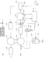
- Fig. 1 is an illustration of one embodiment of a fuel system 100.
- a fuel control valve 104 such as a TecJet, enables fuel to flow to a compressor 110.
- the resulting air/fuel mixture passes through an aftercooler 114.
- a throttle 116 controls the volume of air/fuel mixture that flows into an intake manifold 118.
- the manifold 118 delivers the fuel to one or more cylinders 120.
- Fig. 1 illustrates one cylinder 120 for exemplary reasons, however it is known in the art to deliver fuel from the manifold 118 to multiple cylinders 120.
- the exhaust from the cylinders 120 passes through the exhaust manifold 122, the turbine 112, and the exhaust stack 124.
- a bypass control valve 142 may be connected between the output of the aftercooler 114 and the input of the compressor 110.
- a controller 102 may receive inputs from one or more sensors.
- the controller 102 controls the speed of the engine by determining a load characteristic of the engine, determining a change in the load characteristic, and controlling the engine in response to the load change.
- the controller determines at least one of a throttle command, fuel command, and bypass valve position, in response to the load change.
- a throttle command, fuel command, and/or bypass valve position are determined, the appropriate commands are delivered to a throttle actuator 128, a fuel actuator 126, and a bypass valve actuator 140, respectively.
- the throttle actuator 128 will control the position of the throttle 116 in response to the throttle command.
- the fuel valve actuator 126 will control the position of the fuel control valve 104 in response to the fuel command.
- the bypass valve actuator 140 will control the position of the bypass valve 142 in response to the bypass valve command.
- an actual engine speed sensor 134 may be included in the fuel system 100.
- the actual engine speed sensor 134 is attached to the engine and electrically connected to the controller 102.
- the speed sensor 134 may be any type of sensor that produces an electrical signal indicative of the engine speed.
- the speed sensor 134 is mounted on an engine flywheel housing (not shown) and produces a digital speed signal in response to the speed of the flywheel mounted on an engine crankshaft (not shown).
- the fuel system includes a load sensor 144 adapted to sense a characteristic of the load of the engine, and responsively deliver a load signal to the controller.
- the load sensor 144 may be attached to the engine and adapted to detect the external load being applied to the engine.
- the load sensor 144 may be attached to an engine and sense a characteristic of the external load in kilowatts, amps, or volts, that is being applied to the engine.
- the load signal is then delivered to the controller 102.
- the load of the engine may be determined using software. For example, the load may be determined in response to determining the amount of fuel being required by the engine.
- Other sensors such as a pressure sensor 130, and/or temperature sensor 132 may be included in the fuel system 100.
- the variables sensed by these apparatus may be used by the controller 102 to determine a fuel command.
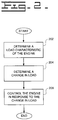
- Fig. 2 illustrates one embodiment of the method of the present invention.
- the present invention includes a method for controlling the speed of an engine, including the steps of determining a load characteristic of the engine, determining a change in the load characteristic, and controlling the engine in response to the load change.
- a load characteristic of the engine is determined.
- the load characteristic is the load of the engine.
- a load sensor 144 may be used to sense a load characteristic of the engine, and deliver a signal indicative of the load characteristic to the controller 102.
- the load characteristic is the actual load of the engine, e.g., the external load being applied to the engine.
- other techniques may be used to determine an engine load characteristic such as determining a load value in response to the fuel command. That is, the fuel command may be indicative of the external load applied to the engine.
- a change in the engine load is determined.
- the current engine load may be compared with a previous engine load. The comparison is indicative of a change in the engine load.
- the engine is controlled in response to the load change.
- the engine load is monitored to determine when an engine overspeed condition exists.
- the engine may then be controlled in response to the overspeed condition.
- an engine overspeed condition may be determined in response to a change in the engine load over a time period. That is, when a change in engine load over a time period exceeds a threshold value, an overspeed condition may be determined to exist. For example, if the current sensed load drops below a previously sensed load by a threshold hold value within a specified time period, then an engine overspeed condition may be determined to exist.
- the time period may be dynamically determined or may be a predetermined value.
- the threshold may also either be a predetermined or dynamically determined value.
- the threshold value may be dynamically determined in response to the magnitude of the engine load. A larger engine load may result in a larger threshold, or change in load value, which must be exceeded before an engine overspeed condition is determined to exist.
- monitoring the change in engine load over a specified time period may indicate the likely occurrence of an engine overspeed condition. Therefore, the engine may be controlled in response to a likely overspeed condition, by monitoring the engine load.
- the engine is controlled in response to the load change.
- the determined change in engine load is compared to a threshold, e.g., an overspeed threshold.
- the engine is then controlled in response to the comparison. If the magnitude of the load change does not exceed the overspeed threshold, then the engine is controlled in a normal manner, as discussed below. If the magnitude of the load change exceeds the overspeed threshold, then at least one of a fuel command, throttle command, and a bypass control command are determined in response to the load change, and specifically to the comparison of the load change to an overspeed threshold.
- the engine may be controlled by determining at least one of a throttle command, fuel command, and a bypass control command in response to the load change.
- each of the throttle, fuel, and bypass valve, commands are controlled in response to the load change.
- Fig. 3 illustrates one embodiment of a functional block diagram of the present invention.
- the initial fuel command generated by the fuel command governor 306 is passed to an overspeed control 308. If an overspeed condition does not exist, for example the load change does not exceed the overspeed threshold, then the initial fuel command passes through the overspeed control 308, unmodified, and is delivered to the fuel actuator 126.
- An actual engine speed may be determined in response to the speed sensor signal generated by the speed sensor 134.
- a desired engine speed may be established either dynamically or based upon predetermined data.
- the desired engine speed may be dynamically established in response to receiving a desired engine speed signal.
- the desired speed signal may be representative of an input throttle command, from an operator for example, or by a cruise control system (not shown).
- the desired engine speed may be a predetermined value.
- a throttle command is determined in order to control the amount of air/fuel mixture that flows into the manifold 118.
- the throttle command is determined in response to a comparison of the desired and actual engine speeds, e.g., the engine speed error.
- the throttle command may be determined utilizing a proportional, integral, derivative (PID) control algorithm.
- PID control algorithm receives the engine speed error, and responsively determines a throttle command.
- PID control algorithms are well known in the art. An example of a PID control algorithm is shown below.
- the controller 102 also controls the quantity of fuel flowing to the turbo 110.
- the controller 102 determines a fuel command, and delivers the command to the fuel control valve 126.
- the fuel command controls the amount of fuel to be delivered to the turbo 110, thereby controlling the ratio of air to fuel in the mixture which is delivered to the manifold 118.
- a fuel command is determined by a functional fuel governor 306, illustrated in Fig. 3.
- the fuel governor 306 may receive inputs from the speed sensor 134, pressure sensor 130, and temperature sensor 132, and responsively determine a fuel command. If an overspeed condition does not exist, e.g., the load change is less than an overspeed threshold, then the fuel command is delivered to the fuel actuator 126 unmodified. If an overspeed condition does exist, the fuel command may be modified, as discussed below.
- the bypass control valve 142 is either closed or open. Under normal operating conditions, e.g., an overspeed condition does not exist, the bypass control valve 142 is closed. When an overspeed condition does exist, the bypass control valve 142 may be commanded open. If an overspeed condition does not exist, e.g., the load change is less than an overspeed threshold, then the bypass valve command is delivered to the bypass valve 142 unmodified, and the valve 142 is commanded closed. If an overspeed condition does exist, the bypass valve command may be modified, as discussed below.
- the functional diagram illustrated in Fig. 3 is for illustrative purposes only.
- the present invention may be functionally represented in many different manners.
- the fuel governor 306, throttle governor 302, and bypass valve governors 312 may include the respective overspeed control blocks 304, 308, 314.
- the overspeed control blocks are developed in software and may be implemented with the governors or separately.
- an overspeed indicator 310 may be included to determine the existence of an overspeed condition, e.g., the load change exceeds an overspeed threshold.
- a signal indicative of whether an overspeed condition exist may be delivered to the overspeed controls 304, 308, 312.
- the load signal may be delivered directly to the overspeed control 304, 308, 312.
- Fig. 4 illustrates a flow diagram of one embodiment of determining a fuel command in response to the load change.
- a first control block 402 an initial fuel command is determined.
- the initial fuel command is then modified in response to the change in load.
- the fuel command is reduced for a specified period of time in response to the load change.
- the reduced fuel command is then delivered to the fuel actuator 126 for the specified time period.
- Reduced Fuel Cmd X% * Initial Fuel Cmd
- X is a variable
- X is a variable, the value of which is based upon the change in load. For example, the larger the change in load, the larger X is, and therefore, the smaller the reduced fuel command is.
- X may be a constant. The specific value of X may be dependent on the type of the engine used, and the type of performance desired.
- the reduced fuel command is delivered to the fuel actuator 126 for a specified time period. In one embodiment, the fuel command is delivered for a predetermined amount of time, e.g., one second. In an alternative embodiment, the time period may be dynamically determined. For example, the length of time the fuel command is reduced may be based on the magnitude of the load change, e.g., the severity of the overspeed condition. A larger load change may result in a longer time period for generating the reduced fuel command. The length of time the reduced fuel command is delivered may be engine and implementation dependent. After the specified time period expires control passes to control block 406.
- a fuel command may be determined in response to a desired and an actual engine speed.
- An fuel command is generated by the fuel command governor 306 and passed to the overspeed control 308.
- the fuel command is modified in response to a desired and the actual engine speed.
- the desired and actual engine speeds are compared to determine an engine speed error.
- a modified fuel command is determined in response to the engine speed error.
- a modified fuel command may be determined in response to multiplying the engine speed error by a constant and subtracting the sum from the fuel command received from the fuel governor 306.
- the constant may be a predetermined or dynamically determined value. In one embodiment, the constant is a proportional gain constant.
- the modified fuel command is compared with a minimum fuel command. If the modified fuel command is less than the minimum fuel command then the modified fuel command is set equal to the minimum fuel command.
- the minimum fuel command may be either a predetermined or dyanmically determined value. For example, a minimum fuel command may be dynamically determined in response to the magnitude of the change in the load, and the load value before the load change occurred.
- each of the steps illustrated in Fig. 4 is performed.
- the fuel command is reduced in response to the change in engine load, for a specified time period.
- the reduced fuel command is delivered to the fuel actuator 126 for a specified period of time.
- a fuel command is then modified in response to the desired and actual engine speeds.
- the modified fuel command is compared with minimum fuel command, and the greater of the modified and minimum fuel command is delivered to the fuel actuator 126.
- determination of the fuel command may include one or more of the described steps. For example, in one embodiment, when the magnitude of the load change exceeds an overspeed threshold, the fuel command may be reduced for a specified period of time. Alternatively, the fuel command may be determined in response to the desired and actual engine speeds, when an overspeed condition is determined to exist.
- a throttle command is determined in response to the load change.
- a throttle command is determined by a throttle governor 302.
- the throttle command e.g., an intial throttle command
- the throttle command is then delivered to an overspeed control 304. If an overspeed condition does exist, e.g., the load change exceeds a threshold value, then the initial throttle command is reduced at a specified rate.
- the initial, or base, throttle command generated by the throttle governor 302 is reduced at a specified rate, e.g., 10%/sec. Therefore, after one second, for example, the throttle command has been reduced to 90% of the initial value determined by the throttle governor 302.
- the reduced throttle command is delivered to the throttle actuator 128 during this time period.
- the reduced throttle command has been further reduced by 10% of the value of the initial, or base, throttle command.
- the reduction rate may be either predetermined or dynamically determined in response to the engine load or engine speed. In addition the reduction rate may remain the same, e.g., 10%/sec., or may vary depending on the length time the overspeed condition exists.
- the reduced throttle command is compared to the current throttle command received by the throttle governor 302. If the reduced throttle command is greater than the current throttle command, the reduced throttle command is sent to the throttle actuator 128. If the reduced throttle command is not greater than the current throttle command, then the current throttle command is delivered to the actuator 128.
- the bypass control valve 142 when an overspeed condition exist, the bypass control valve 142 is opened for a specified time period, e.g., one second.
- the length of time the valve 142 is open may be implementation dependent.
- the length of time the valve is opened may be a predetermined, or dynamically determined value. If the value is dynamically determined, the value may be determined in response to the magnitude of the change in the load.
- bypass control valve 142 may be fully opened or partially opened for a specified amount of time when an overspeed condition exists. If the bypass control valve 142 was partially opened when no overspeed condition existed, then the valve position would be increased, e.g., further opened, when an overspeed condition is detected.
- an engine overspeed condition is determined to exist, e.g., a load change exceeds an overspeed threshold
- the engine speed is monitored to determine when the overspeed condition no long exists, i.e., the engine overspeed condition is over.
- the actual engine speed is compared with a desired engine speed.
- An engine speed error may be determined in response to the comparison. If the absolute value of the engine speed error is less than an error threshold, then the overspeed status may be determined to no longer exist.
- the error threshold may be either a predetermined, or dynamically determined value.
- the bypass valve is closed, if it is currently open, and the throttle, fuel, and bypass valve commands are determined by the throttle governor 302 and fuel governor 306 and bypass valve governor 312 respectively, and pass through the respective overspeed control blocks 304, 308, 314 unmodified.
- the fuel command, throttle command, and bypass control valve command may be determined independent of each other.
- the overspeed control functional blocks (304, 308, 314) may be included in the throttle governor 302, fuel governor 306, and bypass control valve governor 312 respectively.
- the present invention provides a method and apparatus for controlling the speed of an engine.
- the engine has an associated turbo charger and a throttle.
- the method includes the steps of determining a load characteristic of the engine, determining a change in the load characteristic, and controlling the engine in response to the load change.
- the desired engine speed is less than the actual engine speed.
- the fuel control system may attempt to compensate for the load reduction in a manner that results in speed oscillations and poor engine performance. For example, when an overspeed condition occurs, e.g., the desired engine speed is less than the actual engine speed, a fuel control system may attempt to greatly reduce, or close the throttle. However, when this is done the desired speed may soon be much greater than the actual speed. The rapid speed changes due to the significant load changes may lead to overcompensation by the fuel system which may lead to speed instability or oscillations. Therefore, at least one of the fuel command, throttle command, and bypass control valve commands are modified in response to the change in load. In the preferred embodiment each of the commands is modified in response to the load change.
- the fuel command, throttle command and bypass valve command continue to be modified in response to the load change until the overspeed condition has been resolved.
- the overspeed condition is determined to be resolved in response to the desired and actual engine speeds. For example, the desired and actual engine speeds may be compared to determine an engine speed error. If the absolute value of the engine speed error is less than an error threshold, then the overspeed condition may be considered resolved, and the fuel, throttle, and bypass control valve commands may be determined as they were under normal operating conditions.
Applications Claiming Priority (2)
| Application Number | Priority Date | Filing Date | Title |
|---|---|---|---|
| US458282 | 1983-01-14 | ||
| US09/458,282 US6345602B1 (en) | 1999-12-10 | 1999-12-10 | Method and apparatus for controlling the speed of an engine |
Publications (2)
| Publication Number | Publication Date |
|---|---|
| EP1106806A2 true EP1106806A2 (fr) | 2001-06-13 |
| EP1106806A3 EP1106806A3 (fr) | 2002-12-11 |
Family
ID=23820146
Family Applications (1)
| Application Number | Title | Priority Date | Filing Date |
|---|---|---|---|
| EP00122966A Withdrawn EP1106806A3 (fr) | 1999-12-10 | 2000-10-23 | Méthode et appareil pour commander la vitesse d'un moteur |
Country Status (2)
| Country | Link |
|---|---|
| US (1) | US6345602B1 (fr) |
| EP (1) | EP1106806A3 (fr) |
Families Citing this family (7)
| Publication number | Priority date | Publication date | Assignee | Title |
|---|---|---|---|---|
| US7545854B1 (en) * | 1998-09-01 | 2009-06-09 | Sirf Technology, Inc. | Doppler corrected spread spectrum matched filter |
| US20060275151A1 (en) * | 2005-06-01 | 2006-12-07 | Caterpillar Inc. | Pump and heat exchanger |
| US7818970B2 (en) * | 2005-09-12 | 2010-10-26 | Rolls-Royce Power Engineering Plc | Controlling a gas turbine engine with a transient load |
| US7788923B2 (en) * | 2006-02-02 | 2010-09-07 | International Engine Intellectual Property Company, Llc | Constant EGR rate engine and method |
| US8061137B2 (en) * | 2008-05-30 | 2011-11-22 | Caterpillar Inc. | Fuel control system for limiting turbocharger speed |
| US9683498B2 (en) | 2015-05-19 | 2017-06-20 | Caterpillar Inc. | Turbocharger compressor anti-surge engine control strategy and method |
| US10344695B1 (en) * | 2018-03-12 | 2019-07-09 | Cummins Inc. | Engine controls including dynamic load correction |
Citations (6)
| Publication number | Priority date | Publication date | Assignee | Title |
|---|---|---|---|---|
| DE2414293A1 (de) * | 1974-03-25 | 1975-10-16 | Yanmar Diesel Engine Co | Last-kompensationseinrichtung fuer lader-brennkraftmaschine |
| JPS5928021A (ja) * | 1982-08-06 | 1984-02-14 | Mazda Motor Corp | エンジンの吸気装置 |
| JPS6022032A (ja) * | 1983-07-19 | 1985-02-04 | Mitsubishi Heavy Ind Ltd | 過給デイ−ゼル発電装置の制御装置 |
| DE3400951A1 (de) * | 1984-01-13 | 1985-07-18 | Robert Bosch Gmbh, 7000 Stuttgart | Verfahren und vorrichtung zur drehzahlregelung bei einer brennkraftmaschine |
| JPS61234247A (ja) * | 1985-03-27 | 1986-10-18 | Toyota Motor Corp | デイ−ゼルエンジンの燃料噴射量制御方法 |
| US6196189B1 (en) * | 1999-06-18 | 2001-03-06 | Caterpillar Inc. | Method and apparatus for controlling the speed of an engine |
Family Cites Families (11)
| Publication number | Priority date | Publication date | Assignee | Title |
|---|---|---|---|---|
| US4257361A (en) * | 1979-06-11 | 1981-03-24 | Kasiewicz Stanley Joseph | Control circuit for engine speed governor |
| JPS56167814A (en) * | 1980-05-28 | 1981-12-23 | Hitachi Ltd | Apparatus and method for controlling supercharger of internal combustion engine |
| US4493303A (en) * | 1983-04-04 | 1985-01-15 | Mack Trucks, Inc. | Engine control |
| JPS6181546A (ja) * | 1984-09-28 | 1986-04-25 | Honda Motor Co Ltd | 内燃エンジンのアイドル回転数フイ−ドバツク制御方法 |
| JP2621548B2 (ja) | 1990-02-23 | 1997-06-18 | 三菱電機株式会社 | エンジンの制御装置 |
| US5313798A (en) | 1991-08-02 | 1994-05-24 | Toyota Jidosha Kabushiki Kaisha | Charging control apparatus for an internal combustion engine with a dual turbocharger system |
| US6035825A (en) * | 1993-10-21 | 2000-03-14 | Orbital Engine Company (Australia) Pty Limited | Control of fueling rate of an engine |
| JPH08114142A (ja) * | 1994-10-17 | 1996-05-07 | Fuji Heavy Ind Ltd | エンジンのアイドル制御方法 |
| US5724813A (en) | 1996-01-26 | 1998-03-10 | Caterpillar Inc. | Compressor by-pass and valving for a turbocharger |
| US5816047A (en) | 1996-09-03 | 1998-10-06 | Dresser Industries, Inc. | Electronically controlled wastegate valve for a turbo charger |
| US6012289A (en) * | 1997-11-19 | 2000-01-11 | Caterpillar Inc. | Apparatus and method for utilizing a learned wastegate control signal for controlling turbocharger operation |
-
1999
- 1999-12-10 US US09/458,282 patent/US6345602B1/en not_active Expired - Lifetime
-
2000
- 2000-10-23 EP EP00122966A patent/EP1106806A3/fr not_active Withdrawn
Patent Citations (6)
| Publication number | Priority date | Publication date | Assignee | Title |
|---|---|---|---|---|
| DE2414293A1 (de) * | 1974-03-25 | 1975-10-16 | Yanmar Diesel Engine Co | Last-kompensationseinrichtung fuer lader-brennkraftmaschine |
| JPS5928021A (ja) * | 1982-08-06 | 1984-02-14 | Mazda Motor Corp | エンジンの吸気装置 |
| JPS6022032A (ja) * | 1983-07-19 | 1985-02-04 | Mitsubishi Heavy Ind Ltd | 過給デイ−ゼル発電装置の制御装置 |
| DE3400951A1 (de) * | 1984-01-13 | 1985-07-18 | Robert Bosch Gmbh, 7000 Stuttgart | Verfahren und vorrichtung zur drehzahlregelung bei einer brennkraftmaschine |
| JPS61234247A (ja) * | 1985-03-27 | 1986-10-18 | Toyota Motor Corp | デイ−ゼルエンジンの燃料噴射量制御方法 |
| US6196189B1 (en) * | 1999-06-18 | 2001-03-06 | Caterpillar Inc. | Method and apparatus for controlling the speed of an engine |
Non-Patent Citations (3)
| Title |
|---|
| PATENT ABSTRACTS OF JAPAN vol. 008, no. 124 (M-301), 9 June 1984 (1984-06-09) & JP 59 028021 A (TOYO KOGYO KK), 14 February 1984 (1984-02-14) * |
| PATENT ABSTRACTS OF JAPAN vol. 009, no. 142 (M-388), 18 June 1985 (1985-06-18) & JP 60 022032 A (MITSUBISHI JUKOGYO KK), 4 February 1985 (1985-02-04) * |
| PATENT ABSTRACTS OF JAPAN vol. 011, no. 078 (M-570), 10 March 1987 (1987-03-10) & JP 61 234247 A (TOYOTA MOTOR CORP), 18 October 1986 (1986-10-18) * |
Also Published As
| Publication number | Publication date |
|---|---|
| US6345602B1 (en) | 2002-02-12 |
| EP1106806A3 (fr) | 2002-12-11 |
Similar Documents
| Publication | Publication Date | Title |
|---|---|---|
| US7540148B2 (en) | Method and device for operating at least one turbocharger on an internal combustion engine | |
| KR100752456B1 (ko) | 내연기관의 과급압 제어 방법 및 장치 | |
| US6718767B1 (en) | Variable geometry turbocharger control system | |
| EP1801384B1 (fr) | Procédés et systèmes de contrôle du turbocompresseur à géométrie variable | |
| US6012289A (en) | Apparatus and method for utilizing a learned wastegate control signal for controlling turbocharger operation | |
| US5442918A (en) | Automatic supercharging control system for an internal combustion engine | |
| US6155050A (en) | System and method for protecting a turbocharger in the event of a wastegate failure | |
| JP2008025529A (ja) | エンジンの過給装置における過給圧制御手段の故障検知装置 | |
| US5155998A (en) | Supercharging pressure control system for an automotive engine | |
| US6055811A (en) | Apparatus and method for controlling the air flow into an engine | |
| US6020652A (en) | Process for regulating the braking power of a supercharged internal combustion engine | |
| US9708984B2 (en) | Regulating method for a turbocharger of an internal combustion engine, and turbocharger | |
| US4519210A (en) | Turbocharged internal combustion engine with apparatus for controlling supercharging pressure | |
| US6244050B1 (en) | Apparatus for regulating the pressure in an internal combust ion engine intake ducts | |
| US6196189B1 (en) | Method and apparatus for controlling the speed of an engine | |
| US6345602B1 (en) | Method and apparatus for controlling the speed of an engine | |
| US4709553A (en) | Method of and apparatus for controlling supercharge pressure for a turbocharger | |
| US6725659B1 (en) | Apparatus and method for limiting turbocharger speed | |
| GB2228768A (en) | Supercharging pressure control system for an engine with a turbocharger | |
| JPH0535251B2 (fr) | ||
| US10578010B2 (en) | Control device for an internal combustion engine | |
| US4457275A (en) | Idling speed control system for internal combustion engine | |
| US6581382B2 (en) | Method and apparatus for controlling a supply system for a combustion engine | |
| JP3105402B2 (ja) | 過給圧制御方法 | |
| CN110005517A (zh) | 用于使发动机组件运转的方法 |
Legal Events
| Date | Code | Title | Description |
|---|---|---|---|
| PUAI | Public reference made under article 153(3) epc to a published international application that has entered the european phase |
Free format text: ORIGINAL CODE: 0009012 |
|
| AK | Designated contracting states |
Kind code of ref document: A2 Designated state(s): AT BE CH CY DE DK ES FI FR GB GR IE IT LI LU MC NL PT SE |
|
| AX | Request for extension of the european patent |
Free format text: AL;LT;LV;MK;RO;SI |
|
| PUAL | Search report despatched |
Free format text: ORIGINAL CODE: 0009013 |
|
| AK | Designated contracting states |
Kind code of ref document: A3 Designated state(s): AT BE CH CY DE DK ES FI FR GB GR IE IT LI LU MC NL PT SE |
|
| AX | Request for extension of the european patent |
Free format text: AL;LT;LV;MK;RO;SI |
|
| AKX | Designation fees paid |
Designated state(s): AT DE FI |
|
| STAA | Information on the status of an ep patent application or granted ep patent |
Free format text: STATUS: THE APPLICATION IS DEEMED TO BE WITHDRAWN |
|
| 18D | Application deemed to be withdrawn |
Effective date: 20030611 |