Technical Field
-
This invention relates generally to an
engine, and more particularly, to a method and
apparatus for controlling the speed of an engine.
Background Art
-
Electronic control of fuel systems on an
engine generally provide a determined amount of fuel
to the engine in response to a desired and an actual
engine speed. In one embodiment, the engine may have
an associated turbocharger. When the load on the
engine is quickly removed, an engine overspeed or
turbo surge may result. That is, when the load is
removed suddenly from the engine, the engine may
rapidly accelerate above the desired engine speed.
The speed of the engine and the turbocharger may begin
to surge uncontrollably. Current fuel control systems
may be unable to stabilize the engine speed, in part,
because of the sudden and significant difference
between the desired and actual engine speed.
-
The present invention is directed to
overcoming one or more of the problems identified
above.
Disclosure of the Invention
-
In one aspect of the present invention, a
method for controlling the speed of an engine is
disclosed. The engine has an associated turbocharger
and a throttle. The method includes the steps of
determining a load characteristic of the engine, and
controlling the engine in response to the load
characteristic.
-
In another aspect of the present invention, an
apparatus for controlling the speed of an engine is
disclosed. The apparatus comprises a speed sensor
adapted to sense a characteristic of the engine and
responsively generate a speed signal indicative of the
speed of the engine, and a controller adapted to
receive the speed signal, determine a load
characteristic of the engine, determine a change in
the load characteristic, and control the engine in
response to the load change.
Brief Description of the Drawings
-
- Fig. 1 is a high level diagram of one
embodiment of a fuel system;
- Fig. 2 is an illustration of one embodiment
of a method of controlling the speed of an engine;
- Fig. 3 is a functional block diagram of an
system adapted to control the speed of an engine; and
- Fig. 4 is an illustration of one embodiment
of a method for determining a fuel command in response
to a load change.
-
Best Mode for Carrying Out the Invention
-
The present invention provides a method and
apparatus for controlling the speed of an engine. In
the preferred embodiment, the engine has an associated
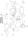
turbocharger and a throttle. Fig. 1 is an
illustration of one embodiment of a fuel system 100.
A fuel control valve 104, such as a TecJet, enables
fuel to flow to a compressor 110. The resulting
air/fuel mixture passes through an aftercooler 114. A
throttle 116 controls the volume of air/fuel mixture
that flows into an intake manifold 118. The manifold
118 delivers the fuel to one or more cylinders 120.
Fig. 1 illustrates one cylinder 120 for exemplary
reasons, however it is known in the art to deliver
fuel from the manifold 118 to multiple cylinders 120.
The exhaust from the cylinders 120 passes through the
exhaust manifold 122, the turbine 112, and the exhaust
stack 124. A bypass control valve 142 may be
connected between the output of the aftercooler 114
and the input of the compressor 110.
-
A controller 102 may receive inputs from one
or more sensors. The controller 102 controls the
speed of the engine by determining a load
characteristic of the engine, determining a change in
the load characteristic, and controlling the engine in
response to the load change. In one embodiment, the
controller determines at least one of a throttle
command, fuel command, and bypass valve position, in
response to the load change. When a throttle command,
fuel command, and/or bypass valve position are
determined, the appropriate commands are delivered to
a throttle actuator 128, a fuel actuator 126, and a
bypass valve actuator 140, respectively. The throttle
actuator 128 will control the position of the throttle
116 in response to the throttle command. The fuel
valve actuator 126 will control the position of the
fuel control valve 104 in response to the fuel
command. The bypass valve actuator 140 will control
the position of the bypass valve 142 in response to
the bypass valve command.
-
In one embodiment, an actual engine speed
sensor 134 may be included in the fuel system 100.
The actual engine speed sensor 134 is attached to the
engine and electrically connected to the controller
102. The speed sensor 134 may be any type of sensor
that produces an electrical signal indicative of the
engine speed. For example, in one embodiment, the
speed sensor 134 is mounted on an engine flywheel
housing (not shown) and produces a digital speed
signal in response to the speed of the flywheel
mounted on an engine crankshaft (not shown).
-
In the preferred embodiment, the fuel system
includes a load sensor 144 adapted to sense a
characteristic of the load of the engine, and
responsively deliver a load signal to the controller.
In one embodiment, the load sensor 144 may be attached
to the engine and adapted to detect the external load
being applied to the engine. For example, the load
sensor 144 may be attached to an engine and sense a
characteristic of the external load in kilowatts,
amps, or volts, that is being applied to the engine.
The load signal is then delivered to the controller
102. In an alternative embodiment, the load of the
engine may be determined using software. For example,
the load may be determined in response to determining
the amount of fuel being required by the engine.
-
Other sensors such as a pressure sensor 130,
and/or temperature sensor 132 may be included in the
fuel system 100. The variables sensed by these
apparatus may be used by the controller 102 to
determine a fuel command.
-
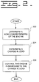
Fig. 2 illustrates one embodiment of the
method of the present invention. The present
invention includes a method for controlling the speed
of an engine, including the steps of determining a
load characteristic of the engine, determining a
change in the load characteristic, and controlling the
engine in response to the load change.
-
In a first control block 202, a load
characteristic of the engine is determined. In the
preferred embodiment, the load characteristic is the
load of the engine. In one embodiment, a load sensor
144 may be used to sense a load characteristic of the
engine, and deliver a signal indicative of the load
characteristic to the controller 102. In the
preferred embodiment the load characteristic is the
actual load of the engine, e.g., the external load
being applied to the engine. However, other
techniques may be used to determine an engine load
characteristic such as determining a load value in
response to the fuel command. That is, the fuel
command may be indicative of the external load applied
to the engine.
-
In a second control block 204, a change in
the engine load is determined. For example, the
current engine load may be compared with a previous
engine load. The comparison is indicative of a change
in the engine load.
-
In a third control block 206, the engine is
controlled in response to the load change. In one
embodiment, the engine load is monitored to determine
when an engine overspeed condition exists. The engine
may then be controlled in response to the overspeed
condition. In one embodiment, an engine overspeed
condition may be determined in response to a change in
the engine load over a time period. That is, when a
change in engine load over a time period exceeds a
threshold value, an overspeed condition may be
determined to exist. For example, if the current
sensed load drops below a previously sensed load by a
threshold hold value within a specified time period,
then an engine overspeed condition may be determined
to exist. The time period may be dynamically
determined or may be a predetermined value. The
threshold may also either be a predetermined or
dynamically determined value. For example, the
threshold value may be dynamically determined in
response to the magnitude of the engine load. A
larger engine load may result in a larger threshold,
or change in load value, which must be exceeded before
an engine overspeed condition is determined to exist.
-
In an alternative embodiment, monitoring the
change in engine load over a specified time period may
indicate the likely occurrence of an engine overspeed
condition. Therefore, the engine may be controlled in
response to a likely overspeed condition, by
monitoring the engine load.
-
In another alternative embodiment, the
engine is controlled in response to the load change.
The determined change in engine load is compared to a
threshold, e.g., an overspeed threshold. The engine
is then controlled in response to the comparison. If
the magnitude of the load change does not exceed the
overspeed threshold, then the engine is controlled in
a normal manner, as discussed below. If the magnitude
of the load change exceeds the overspeed threshold,
then at least one of a fuel command, throttle command,
and a bypass control command are determined in
response to the load change, and specifically to the
comparison of the load change to an overspeed
threshold.
-
The engine may be controlled by determining
at least one of a throttle command, fuel command, and
a bypass control command in response to the load
change. In the preferred embodiment, each of the
throttle, fuel, and bypass valve, commands are
controlled in response to the load change.
-
Fig. 3 illustrates one embodiment of a
functional block diagram of the present invention.
The initial fuel command generated by the fuel command
governor 306 is passed to an overspeed control 308.
If an overspeed condition does not exist, for example
the load change does not exceed the overspeed
threshold, then the initial fuel command passes
through the overspeed control 308, unmodified, and is
delivered to the fuel actuator 126.
-
An actual engine speed may be determined in
response to the speed sensor signal generated by the
speed sensor 134. A desired engine speed may be
established either dynamically or based upon
predetermined data. The desired engine speed may be
dynamically established in response to receiving a
desired engine speed signal. The desired speed signal
may be representative of an input throttle command,
from an operator for example, or by a cruise control
system (not shown). Alternatively, the desired engine
speed may be a predetermined value.
-
A throttle command is determined in order to
control the amount of air/fuel mixture that flows into
the
manifold 118. The throttle command is determined
in response to a comparison of the desired and actual
engine speeds, e.g., the engine speed error. The
throttle command may be determined utilizing a
proportional, integral, derivative (PID) control
algorithm. The PID control algorithm receives the
engine speed error, and responsively determines a
throttle command. PID control algorithms are well
known in the art. An example of a PID control
algorithm is shown below.
Where
- ej = error(desired speed - actual speed)
- Ci = Command (Throttle) at time ti
- KP = Proportional gain of the governor
- KI = Integral gain of the governor
- KD = Derivative gain of the governor
In the preferred embodiment the PID algorithm is
included within a throttle governor 304, as
illustrated in Fig. 3. The throttle governor 304
receives the engine speed error and responsively
determines a throttle command. In one embodiment, the
throttle command is delivered to an overspeed control
304. If an overspeed condition does not exist, e.g.,
the load change is less than an overspeed threshold,
then the throttle command is delivered to the throttle
actuator 128 unmodified. If an overspeed condition
does exist, the throttle command may be modified, as
discussed below.-
-
In the fuel control system 100, the
controller 102 also controls the quantity of fuel
flowing to the turbo 110. The controller 102
determines a fuel command, and delivers the command to
the fuel control valve 126. The fuel command controls
the amount of fuel to be delivered to the turbo 110,
thereby controlling the ratio of air to fuel in the
mixture which is delivered to the manifold 118. In
the preferred embodiment, a fuel command is determined
by a functional fuel governor 306, illustrated in Fig.
3. The fuel governor 306 may receive inputs from the
speed sensor 134, pressure sensor 130, and temperature
sensor 132, and responsively determine a fuel command.
If an overspeed condition does not exist, e.g., the
load change is less than an overspeed threshold, then
the fuel command is delivered to the fuel actuator 126
unmodified. If an overspeed condition does exist, the
fuel command may be modified, as discussed below.
-
In one embodiment, the bypass control valve
142 is either closed or open. Under normal operating
conditions, e.g., an overspeed condition does not
exist, the bypass control valve 142 is closed. When
an overspeed condition does exist, the bypass control
valve 142 may be commanded open. If an overspeed
condition does not exist, e.g., the load change is
less than an overspeed threshold, then the bypass
valve command is delivered to the bypass valve 142
unmodified, and the valve 142 is commanded closed. If
an overspeed condition does exist, the bypass valve
command may be modified, as discussed below.
-
The functional diagram illustrated in Fig. 3
is for illustrative purposes only. The present
invention may be functionally represented in many
different manners. For example, the fuel governor
306, throttle governor 302, and bypass valve governors
312, may include the respective overspeed control
blocks 304, 308, 314. The overspeed control blocks
are developed in software and may be implemented with
the governors or separately.
-
In one embodiment, an overspeed indicator
310 may be included to determine the existence of an
overspeed condition, e.g., the load change exceeds an
overspeed threshold. A signal indicative of whether
an overspeed condition exist may be delivered to the
overspeed controls 304, 308, 312. In one alternative
embodiment, the load signal may be delivered directly
to the overspeed control 304, 308, 312.
-
Fig. 4 illustrates a flow diagram of one
embodiment of determining a fuel command in response
to the load change. In a first control block 402 an
initial fuel command is determined. In a second
control block 404, the initial fuel command is then
modified in response to the change in load. In the
preferred embodiment, the fuel command is reduced for
a specified period of time in response to the load
change. The reduced fuel command is then delivered to
the fuel actuator 126 for the specified time period.
For example, in one embodiment:
Reduced Fuel Cmd = X% * Initial Fuel Cmd
Where: X is a variable
In the preferred embodiment, X is a variable, the
value of which is based upon the change in load. For
example, the larger the change in load, the larger X
is, and therefore, the smaller the reduced fuel
command is. In an alternative embodiment, X may be a
constant. The specific value of X may be dependent on
the type of the engine used, and the type of
performance desired. Once the reduced fuel command is
determined, the reduced fuel command is delivered to
the fuel actuator 126 for a specified time period. In
one embodiment, the fuel command is delivered for a
predetermined amount of time, e.g., one second. In an
alternative embodiment, the time period may be
dynamically determined. For example, the length of
time the fuel command is reduced may be based on the
magnitude of the load change, e.g., the severity of
the overspeed condition. A larger load change may
result in a longer time period for generating the
reduced fuel command. The length of time the reduced
fuel command is delivered may be engine and
implementation dependent. After the specified time
period expires control passes to control block 406.
-
In control block 406, a fuel command may be
determined in response to a desired and an actual
engine speed. An fuel command is generated by the
fuel command governor 306 and passed to the overspeed
control 308. The fuel command is modified in response
to a desired and the actual engine speed. The desired
and actual engine speeds are compared to determine an
engine speed error. A modified fuel command is
determined in response to the engine speed error. For
example, a modified fuel command may be determined in
response to multiplying the engine speed error by a
constant and subtracting the sum from the fuel command
received from the fuel governor 306. The constant may
be a predetermined or dynamically determined value.
In one embodiment, the constant is a proportional gain
constant.
-
In a third control block 408, the modified
fuel command is compared with a minimum fuel command.
If the modified fuel command is less than the minimum
fuel command then the modified fuel command is set
equal to the minimum fuel command. The minimum fuel
command may be either a predetermined or dyanmically
determined value. For example, a minimum fuel command
may be dynamically determined in response to the
magnitude of the change in the load, and the load
value before the load change occurred.
-
In the preferred embodiment, each of the
steps illustrated in Fig. 4 is performed. For
example, the fuel command is reduced in response to
the change in engine load, for a specified time
period. The reduced fuel command is delivered to the
fuel actuator 126 for a specified period of time.
After the specified time period, a fuel command is
then modified in response to the desired and actual
engine speeds. The modified fuel command is compared
with minimum fuel command, and the greater of the
modified and minimum fuel command is delivered to the
fuel actuator 126. In an alternative embodiment,
determination of the fuel command may include one or
more of the described steps. For example, in one
embodiment, when the magnitude of the load change
exceeds an overspeed threshold, the fuel command may
be reduced for a specified period of time.
Alternatively, the fuel command may be determined in
response to the desired and actual engine speeds, when
an overspeed condition is determined to exist.
-
In one embodiment, a throttle command is
determined in response to the load change. As
illustrated in Fig. 3, a throttle command is
determined by a throttle governor 302. In one
embodiment, the throttle command, e.g., an intial
throttle command, is then delivered to an overspeed
control 304. If an overspeed condition does exist,
e.g., the load change exceeds a threshold value, then
the initial throttle command is reduced at a specified
rate. For example, the initial, or base, throttle
command generated by the throttle governor 302 is
reduced at a specified rate, e.g., 10%/sec.
Therefore, after one second, for example, the throttle
command has been reduced to 90% of the initial value
determined by the throttle governor 302. The reduced
throttle command is delivered to the throttle actuator
128 during this time period. After two seconds, the
reduced throttle command has been further reduced by
10% of the value of the initial, or base, throttle
command. The reduction rate may be either
predetermined or dynamically determined in response to
the engine load or engine speed. In addition the
reduction rate may remain the same, e.g., 10%/sec., or
may vary depending on the length time the overspeed
condition exists.
-
Once a reduced throttle command has been
determined, the reduced throttle command is compared
to the current throttle command received by the
throttle governor 302. If the reduced throttle
command is greater than the current throttle command,
the reduced throttle command is sent to the throttle
actuator 128. If the reduced throttle command is not
greater than the current throttle command, then the
current throttle command is delivered to the actuator
128.
-
The reduction in throttle command throttle
command continues until the overspeed condition is
resolved.
-
In one embodiment, when an overspeed
condition exist, the bypass control valve 142 is
opened for a specified time period, e.g., one second.
The length of time the valve 142 is open may be
implementation dependent. In addition, the length of
time the valve is opened may be a predetermined, or
dynamically determined value. If the value is
dynamically determined, the value may be determined in
response to the magnitude of the change in the load.
-
In an alternative embodiment, the bypass
control valve 142 may be fully opened or partially
opened for a specified amount of time when an
overspeed condition exists. If the bypass control
valve 142 was partially opened when no overspeed
condition existed, then the valve position would be
increased, e.g., further opened, when an overspeed
condition is detected.
-
In one embodiment, once an engine overspeed
condition is determined to exist, e.g., a load change
exceeds an overspeed threshold, the engine speed is
monitored to determine when the overspeed condition no
long exists, i.e., the engine overspeed condition is
over. The actual engine speed is compared with a
desired engine speed. An engine speed error may be
determined in response to the comparison. If the
absolute value of the engine speed error is less than
an error threshold, then the overspeed status may be
determined to no longer exist. The error threshold
may be either a predetermined, or dynamically
determined value.
-
When the overspeed condition is determined
to no longer exists, e.g., the absolute value of the
engine speed error is less than an error threshold,
then the bypass valve is closed, if it is currently
open, and the throttle, fuel, and bypass valve
commands are determined by the throttle governor 302
and fuel governor 306 and bypass valve governor 312
respectively, and pass through the respective
overspeed control blocks 304, 308, 314 unmodified.
-
As illustrated in Fig. 3, the fuel command,
throttle command, and bypass control valve command may
be determined independent of each other. In addition,
the overspeed control functional blocks (304, 308,
314) may be included in the throttle governor 302,
fuel governor 306, and bypass control valve governor
312 respectively.
Industrial Applicability
-
The present invention provides a method and
apparatus for controlling the speed of an engine. In
the preferred embodiment, the engine has an associated
turbo charger and a throttle. The method includes the
steps of determining a load characteristic of the
engine, determining a change in the load
characteristic, and controlling the engine in response
to the load change.
-
When a load is quickly removed from the
engine, the desired engine speed is less than the
actual engine speed. The fuel control system may
attempt to compensate for the load reduction in a
manner that results in speed oscillations and poor
engine performance. For example, when an overspeed
condition occurs, e.g., the desired engine speed is
less than the actual engine speed, a fuel control
system may attempt to greatly reduce, or close the
throttle. However, when this is done the desired
speed may soon be much greater than the actual speed.
The rapid speed changes due to the significant load
changes may lead to overcompensation by the fuel
system which may lead to speed instability or
oscillations. Therefore, at least one of the fuel
command, throttle command, and bypass control valve
commands are modified in response to the change in
load. In the preferred embodiment each of the
commands is modified in response to the load change.
-
In the preferred embodiment, the fuel
command, throttle command and bypass valve command
continue to be modified in response to the load change
until the overspeed condition has been resolved. In
one embodiment, the overspeed condition is determined
to be resolved in response to the desired and actual
engine speeds. For example, the desired and actual
engine speeds may be compared to determine an engine
speed error. If the absolute value of the engine
speed error is less than an error threshold, then the
overspeed condition may be considered resolved, and
the fuel, throttle, and bypass control valve commands
may be determined as they were under normal operating
conditions.
-
Other aspects, objects, and advantages of
the present invention can be obtained from a study of
the drawings, the disclosure, and the claims.