EP1106773A1 - Mounting device for a drive, and an actuating device for closures or sun screens comprising such a device - Google Patents
Mounting device for a drive, and an actuating device for closures or sun screens comprising such a device Download PDFInfo
- Publication number
- EP1106773A1 EP1106773A1 EP00420241A EP00420241A EP1106773A1 EP 1106773 A1 EP1106773 A1 EP 1106773A1 EP 00420241 A EP00420241 A EP 00420241A EP 00420241 A EP00420241 A EP 00420241A EP 1106773 A1 EP1106773 A1 EP 1106773A1
- Authority
- EP
- European Patent Office
- Prior art keywords
- support
- head
- partition
- trunk
- cheek
- Prior art date
- Legal status (The legal status is an assumption and is not a legal conclusion. Google has not performed a legal analysis and makes no representation as to the accuracy of the status listed.)
- Granted
Links
Images


Classifications
-
- E—FIXED CONSTRUCTIONS
- E06—DOORS, WINDOWS, SHUTTERS, OR ROLLER BLINDS IN GENERAL; LADDERS
- E06B—FIXED OR MOVABLE CLOSURES FOR OPENINGS IN BUILDINGS, VEHICLES, FENCES OR LIKE ENCLOSURES IN GENERAL, e.g. DOORS, WINDOWS, BLINDS, GATES
- E06B9/00—Screening or protective devices for wall or similar openings, with or without operating or securing mechanisms; Closures of similar construction
- E06B9/02—Shutters, movable grilles, or other safety closing devices, e.g. against burglary
- E06B9/08—Roll-type closures
- E06B9/11—Roller shutters
- E06B9/17—Parts or details of roller shutters, e.g. suspension devices, shutter boxes, wicket doors, ventilation openings
- E06B9/174—Bearings specially adapted therefor
Definitions
- the invention relates to a device for fixing a drive member for a winding shaft, in a safe of a locking or protective installation solar.
- the invention also relates to a mechanism for operation of such an installation.
- a drive is generally placed in a trunk or box which can be of the type known from EP-A-0 764 759.
- This trunk includes a space delimited by a side wall of the trunk and by a cheek separating this space from the winding zone of the deck or blind on the aforementioned tree.
- a protruding part of the drive member which may be the head of an electric motor or part of a device mechanical intended to cooperate with a crank or a strap.
- the winding shaft and / or the drive member passes through a central opening in the cheek and support means for the drive member must be provided in this space, these means being most often complex and requiring the tightening of fixing screws.
- the cheek In addition to its function of delimitation of the aforementioned space, the cheek must ensure the guiding of the deck, with blades or flexible, so that it does not deflect parallel to the axis of the tree, to the point of blocking the installation operation.
- the cheek is not held in position in the trunk or box only from its edges and it tends to flex in its central zone under the effect of the forces transmitted by the apron. This has the effect of degrading winding the deck on the tree and reducing the duration life of the installation, especially since the section of the trunk is important.
- the lateral extension (s) of the support act as spacers between the cheek and the trunk end partition, these spacers can be arranged up to near the central opening of the cheek, so that it is effectively maintained in position across its width, including for a section chest important.
- the invention also relates to an operating mechanism a locking or sun protection system which includes a device as previously described.
- Such mechanism is easier to install and more reliable than state of the art mechanisms.
- the mechanism 1 shown in Figures 1 to 3 is provided for the operation of a roller shutter including the deck 2 shown in phantom is suitable for being wrapped around a shaft 3 controlled by an electric motor 4.
- the deck 2 can be with blades or formed from a flexible material.
- the motor 4 is housed inside the shaft 3 which is tubular, this shaft being supported in a trunk or box 5 shown in phantom and of which we note 5 c a lateral end partition.
- XX ′ the axis of rotation of the shaft 3 which is a longitudinal axis of the trunk 5.
- the internal volume of the box 5 includes a winding zone 6 of the deck 2 of the shaft 3 and a zone 7 of the head 4 has positioning the motor 4, the zone 7 being separated from the region 6 by a flange 8 breakthrough a central orifice 8 a for passage of the shaft 3 and of the motor 4.
- the head 4 a of the motor 4 is held in position inside the zone 7 by means of a support 10 mounted on the internal face 5 d of the partition 5 c .
- the support 10 comprises a central part 10 a forming a hollow housing 10 b capable of receiving at least part of the head 4 a .
- This housing 10 b is of generally octagonal section adapted to the end section 4 b of the head 4 a which is also octagonal.
- Two elastic tabs 10 c in the form of a hook are provided for locking the section 4b of the head 4 a in the housing 10 b by cooperation of shapes with suitable zones 4 c of the section 4 b .
- the geometry of the tabs 10 c and of the zones 4 c allows an elastic snap-fitting of the head 4 a in the housing 10 b .
- the bottom of the housing 10 b is pierced with an orifice 10 e intended to surround a central pin 5 e formed on the inner face 5 d of the partition 5 c and extending along the axis XX 'in the direction of the cheek 8
- the cooperation of the elements 5 e and 10 e allows an efficient and rapid positioning of the support 10 relative to the box 5.
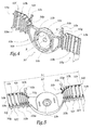
- the support 10 also includes two lateral extensions 10 f and 10 g extending, starting from the part 10 a , radially with respect to the axis XX '.
- the extensions 10 f and 10 g are in one piece with the central part 10 a of the support 10.
- the extensions 10 f and 10 g are formed by unitary elements 10 h linked together by breakable bands 10 i , these breakable bands being formed by a thinned part of each of the extensions 10 f and 10 g .
- each extension 10 f or 10 g is formed of eight elements 10 h connected by seven breakable strips 10 i .
- the number of 10 h elements of the 10 f and 10 g extensions results from a choice of design and can therefore vary.
- each element 10 h is provided with an inscription 10 j corresponding to a nominal diameter of box 5, that is to say substantially to the width l 5 of a box 5 to which the width l 10 of the support 10.
- a nominal diameter of box 5 that is to say substantially to the width l 5 of a box 5 to which the width l 10 of the support 10.
- Each element 10 h is also provided with a lug 10 k intended to be received in a hollow housing 5 k formed on the face 5 d of the partition 5.
- the respective diameters of each lug 10 k and each housing 5 k are adapted to obtain an immobilization of the support 10 relative to the partition 5 c by cooperation of shapes.
- Each element 10 h is also provided, on its rear face visible in FIG. 5, with a projecting part 10 l intended to come into abutment against the face 5 d of the partition 5 c when one of the pins 10 k is in place in one of the 5 k dwellings.
- the protruding parts 10 l form a discontinuous support zone on the partition 5 c which extends to the vicinity of the central part 10 a since the parts 10 l of all the elements 10 h not detached from the part 10 a are in abutment against the inner face 5 d of the partition 5 c .
- some of the elements 10 h carry projections 10 n and 10 m which bear against the face 8 b of the cheek 8 facing towards the zone 7.
- an element 10 h on two has 10 m and 10 n projections. It would be possible to provide that each element 10 h is provided with such projections or, on the contrary, that one element in three or more than three is provided with such projections.
- the projections 10 m and 10 n are distributed close to the central part 10 a of the support 10, so that they contribute to the positioning of the cheek 8 as far as the orifice 8 a , which avoids bending or bulging of the cheek 8 under the effect of the forces transmitted by the apron 2.
- the cheek 8 is thus kept substantially flat, so that it effectively guides the apron 2.
- the distance d between the ends of the projections 10 l on the one hand and 10 m or 10 n on the other hand, measured parallel to the axis XX ′ in the mounted configuration of the device, is equal to the desired width of the area 7, that is to say at the distance separating the faces 5 d and 8 b from the partition 5 c and from the cheek 8 parallel to this axis.
- the support 10 also includes two tabs 10 p and 10 g allowing the reception and immobilization by cooperation of shapes of an electronic circuit 11 for controlling the motor 4.
- the circuit 11 has been represented only by its card holder 11 and has a frame 11b, the card 11 has with practical components and connection paths between these components.
- the geometry of the frame 11b is such that it can be immobilized between tabs 10 r and backsplashes 10 s formed on the legs 10 p and 10 g .
- the installation and immobilization of the circuit 11 on the support 10 are carried out in a particularly simple manner and without interaction with the box 5, the dimensions of which can vary without influence on the installation of the circuit 11.
- the elements 10 p and 10 g , 10 r and 10 s therefore allow mounting by elastic snap-fitting of the circuit 11 on the support 10.
- the support 10 has been shown with the legs 10 p and 10 g integral with the second elements 10 h from the central part 10 a . According to a variant not shown of the invention, these tabs may be integral with the part 10 a , in which case they allow the mounting of the circuit 11 including in a small width trunk.
- the invention has been shown with an electric motor, however, it is applicable to an operating mechanism of a shutter or blind comprising a drive member mechanical part of which forming a "head" is provided for cooperate with a crank or strap.
Landscapes
- Engineering & Computer Science (AREA)
- Structural Engineering (AREA)
- Architecture (AREA)
- Civil Engineering (AREA)
- Operating, Guiding And Securing Of Roll- Type Closing Members (AREA)
- Load-Engaging Elements For Cranes (AREA)
- Discharging, Photosensitive Material Shape In Electrophotography (AREA)
- Power-Operated Mechanisms For Wings (AREA)
- Control Of Motors That Do Not Use Commutators (AREA)
- Photovoltaic Devices (AREA)
Abstract
Description
L'invention a trait à un dispositif de fixation d'un organe d'entraínement pour un arbre d'enroulement, dans un coffre d'une installation de fermeture ou de protection solaire. L'invention a également trait à un mécanisme de manoeuvre d'une telle installation.The invention relates to a device for fixing a drive member for a winding shaft, in a safe of a locking or protective installation solar. The invention also relates to a mechanism for operation of such an installation.
Par installation de fermeture, on entend, les portes, portails, volets et matériels équivalents.The term “closing installation” means the doors, gates, shutters and equivalent equipment.
Il est connu d'utiliser un moteur électrique ou un système mécanique pour entraíner en rotation un arbre d'enroulement d'un tablier de porte ou de volet, ou un store de protection solaire. Un tel organe d'entraínement est généralement disposé dans un coffre ou caisson qui peut être du type connu de EP-A-0 764 759. Ce coffre comprend un espace délimité par une paroi latérale du coffre et par une joue séparant cet espace de la zone d'enroulement du tablier ou du store sur l'arbre précité. Dans cet espace est disposée une partie saillante de l'organe d'entraínement, qui peut être la tête d'un moteur électrique ou une partie d'un dispositif mécanique destiné à coopérer avec une manivelle ou une sangle. L'arbre d'enroulement et/ou l'organe d'entraínement traverse un orifice central de la joue et des moyens de support de l'organe d'entraínement doivent être prévus dans cet espace, ces moyens étant le plus souvent complexes et nécessitant le serrage de vis de fixation. En plus de sa fonction de délimitation de l'espace précité, la joue doit assurer le guidage du tablier, à lames ou souple, afin qu'il ne dévie pas parallèlement à l'axe de l'arbre, au point de bloquer la manoeuvre de l'installation.It is known to use an electric motor or a mechanical system for rotating a shaft of a door or shutter curtain, or a blind sun protection. Such a drive is generally placed in a trunk or box which can be of the type known from EP-A-0 764 759. This trunk includes a space delimited by a side wall of the trunk and by a cheek separating this space from the winding zone of the deck or blind on the aforementioned tree. In this space is arranged a protruding part of the drive member, which may be the head of an electric motor or part of a device mechanical intended to cooperate with a crank or a strap. The winding shaft and / or the drive member passes through a central opening in the cheek and support means for the drive member must be provided in this space, these means being most often complex and requiring the tightening of fixing screws. In addition to its function of delimitation of the aforementioned space, the cheek must ensure the guiding of the deck, with blades or flexible, so that it does not deflect parallel to the axis of the tree, to the point of blocking the installation operation.
Or, la joue n'est maintenue en position dans le coffre ou caisson qu'à partir de ses bords et elle a tendance à fléchir dans sa zone centrale sous l'effet des efforts transmis par le tablier. Ceci a pour effet de dégrader l'enroulement du tablier sur l'arbre et de diminuer la durée de vie de l'installation et ce, d'autant plus que la section du coffre est importante.However, the cheek is not held in position in the trunk or box only from its edges and it tends to flex in its central zone under the effect of the forces transmitted by the apron. This has the effect of degrading winding the deck on the tree and reducing the duration life of the installation, especially since the section of the trunk is important.
C'est à ces inconvénients qu'entend plus particulièrement remédier l'invention en proposant un dispositif de fixation permettant de supporter efficacement la tête d'un organe d'entraínement, alors que le montage de l'installation est simple et que la joue appartenant au coffre ne risque pas de se déformer au contact du tablier en cours d'enroulement, enroulé ou en cours de dévidage.It is to these disadvantages that we hear more particularly remedy the invention by proposing a fixing device to effectively support the head of an organ while the installation of the installation is simple and that the cheek belonging to the chest does not risk deform in contact with the deck during winding, rolled up or being unwound.
Dans cet esprit, l'invention concerne un dispositif de fixation d'un organe d'entraínement pour un arbre d'enroulement dans un coffre d'une installation de fermeture ou de protection solaire, ce coffre formant un volume de réception de la tête de cet organe, ce volume étant séparé d'une zone d'enroulement d'un tablier sur cet arbre par une joue, alors qu'un support est prévu pour cette tête dans ce volume. Ce dispositif est caractérisé en ce que le support comprend une partie centrale apte à être solidarisée avec la tête et au moins une extension latérale pourvue d'au moins un moyen d'écartement de la joue précitée par rapport à une cloison d'extrémité du coffre.In this spirit, the invention relates to a device for fixing a drive member for a winding shaft in a trunk of a locking system or solar protection, this box forming a reception volume of the head of this organ, this volume being separated from an area winding an apron on this tree by a cheek, then that a support is provided for this head in this volume. This device is characterized in that the support comprises a central part capable of being secured to the head and to least one lateral extension provided with at least one means spacing of the aforementioned cheek relative to a partition trunk end.
Grâce à l'invention, la ou les extensions latérales du support jouent le rôle d'entretoises entre la joue et la cloison d'extrémité du coffre, ces entretoises pouvant être disposées jusqu'à proximité de l'orifice central de la joue, de telle sorte que celle-ci est efficacement maintenue en position sur sa largeur, y compris pour un coffre de section importante.Thanks to the invention, the lateral extension (s) of the support act as spacers between the cheek and the trunk end partition, these spacers can be arranged up to near the central opening of the cheek, so that it is effectively maintained in position across its width, including for a section chest important.
Selon des aspects avantageux mais non obligatoires de l'invention, le dispositif incorpore une ou plusieurs des caractéristiques suivantes :
- Chaque extension latérale est formée d'au moins deux éléments reliés par une bande sécable, la géométrie de cette extension étant ajustée à la section du coffre par rupture éventuelle d'une bande sécable. Ainsi, un unique type de support peut être utilisé pour des coffres de sections variables. On peut prévoir que certains au moins des éléments précités sont pourvus d'un ou plusieurs moyens de montage du support sur la cloison d'extrémité du coffre, ces moyens de montage pouvant être des pions aptes à pénétrer dans des logements de formes correspondantes prévus sur la face interne de cette cloison. On peut également prévoir que certains des éléments précités sont pourvus de saillies s'étendant selon une direction globalement parallèle à un axe longitudinal du caisson, ces saillies étant aptes à venir en appui contre la joue et/ou contre la cloison. Dans ce cas, la distance entre les extrémités des saillies parallèlement à cet axe est sensiblement égale à la largeur du volume de réception parallèlement à cet axe. Selon un autre aspect avantageux de l'invention, certains au moins des éléments reliés par une bande sécable portent une mention correspondant à une dimension ou à une référence du coffret à équiper d'un tel support. Cette caractéristique facilite le travail d'un opérateur lorsqu'il ajuste la largeur du support au type de caisson dans lequel il doit être intégré.
- La partie centrale du support forme un logement concave de réception de la tête de l'organe, ce logement étant pourvu de moyens élastiques de retenue de la tête. La tête peut donc être reçue dans la partie centrale du support et immobilisée par coopération de formes, ce qui évite d'avoir recours à des vis ou des dispositifs complexes d'immobilisation.
- Le support est pourvu de moyens de réception d'un boítier ou d'une carte électronique de commande d'un moteur formant organe d'entraínement.
- Each lateral extension is formed of at least two elements connected by a breakable strip, the geometry of this extension being adjusted to the section of the boot by possible breakage of a breakable strip. Thus, a single type of support can be used for boxes of variable sections. Provision may be made for at least some of the aforementioned elements to be provided with one or more means for mounting the support on the end wall of the boot, these mounting means possibly being pins capable of entering housings of corresponding shapes provided on the internal face of this partition. It can also be provided that some of the aforementioned elements are provided with projections extending in a direction generally parallel to a longitudinal axis of the box, these projections being able to come to bear against the cheek and / or against the partition. In this case, the distance between the ends of the projections parallel to this axis is substantially equal to the width of the receiving volume parallel to this axis. According to another advantageous aspect of the invention, at least some of the elements connected by a breakable strip bear a statement corresponding to a dimension or to a reference of the box to be fitted with such a support. This characteristic facilitates the work of an operator when he adjusts the width of the support to the type of box in which it is to be integrated.
- The central part of the support forms a concave housing for receiving the head of the member, this housing being provided with elastic means for retaining the head. The head can therefore be received in the central part of the support and immobilized by cooperation of shapes, which avoids the need for screws or complex immobilization devices.
- The support is provided with means for receiving a housing or an electronic card for controlling a motor forming a drive member.
L'invention concerne également un mécanisme de manoeuvre d'une installation de fermeture ou de protection solaire qui comprend un dispositif tel que précédemment décrit. Un tel mécanisme est plus simple à installer et plus fiable que les mécanismes de l'état de la technique.The invention also relates to an operating mechanism a locking or sun protection system which includes a device as previously described. Such mechanism is easier to install and more reliable than state of the art mechanisms.
L'invention sera mieux comprise et d'autres avantages de celle-ci apparaítront plus clairement à la lumière de la description qui va suivre d'un mécanisme de manoeuvre d'une installation de fermeture conforme à l'invention, donnée uniquement à titre d'exemple et faite en référence aux dessins annexés dans lesquels :
- La figure 1 est une vue en perspective éclatée d'une partie d'un mécanisme de manoeuvre d'une installation de fermeture conforme à l'invention ;
- La figure 2 est une vue en perspective de la partie du dispositif représenté à la figure 1 en configuration montée ;
- La figure 3 est une coupe selon la ligne III-III à la figure 2 ;
- La figure 4 est une vue en perspective d'un support utilisé dans le mécanisme des figures 1 à 3, vu par l'avant et
- La figure 5 est une vue en perspective du support de la figure 4, vu par l'arrière.
- Figure 1 is an exploded perspective view of part of an operating mechanism of a closing installation according to the invention;
- Figure 2 is a perspective view of the part of the device shown in Figure 1 in mounted configuration;
- Figure 3 is a section along line III-III in Figure 2;
- FIG. 4 is a perspective view of a support used in the mechanism of FIGS. 1 to 3, seen from the front and
- Figure 5 is a perspective view of the support of Figure 4, seen from the rear.
Le mécanisme 1 représenté aux figures 1 à 3 est prévu
pour la manoeuvre d'un volet roulant dont le tablier 2
représenté en traits mixtes est apte à être enroulé autour
d'un arbre 3 commandé par un moteur électrique 4. Le tablier
2 peut être à lames ou formé dans un matériau souple.The
Le moteur 4 est logé à l'intérieur de l'arbre 3 qui est
tubulaire, cet arbre étant supporté dans un coffre ou caisson
5 représenté en traits mixtes et dont on note 5c une cloison
latérale d'extrémité. On note X-X' l'axe de rotation de
l'arbre 3 qui est un axe longitudinal du coffre 5.The
Le volume intérieur du caisson 5 comprend une zone 6
d'enroulement du tablier 2 sur l'arbre 3 et une zone 7 de
positionnement de la tête 4a du moteur 4, la zone 7 étant
séparée de la zone 6 par une joue 8 percée d'un orifice
central 8a de passage de l'arbre 3 et du moteur 4.The internal volume of the
Conformément à l'invention, la tête 4a du moteur 4 est
maintenue en position à l'intérieur de la zone 7 grâce à un
support 10 monté sur la face intérieure 5d de la cloison 5c.
Le support 10 comprend une partie centrale 10a formant un
logement en creux 10b apte à recevoir une partie au moins de
la tête 4a. Ce logement 10b est à section globalement
octogonale adaptée à la section d'extrémité 4b de la tête 4a
qui est également octogonale. Deux pattes élastiques 10c en
forme de crochet sont prévues pour verrouiller la section 4b
de la tête 4a dans le logement 10b par coopération de formes
avec des zones adaptées 4c de la section 4b. Comme il ressort
plus particulièrement de la figure 3, la géométrie des pattes
10c et des zones 4c permet un encliquetage élastique de la
tête 4a dans le logement 10b.According to the invention, the
Le fond du logement 10b est percé d'un orifice 10e
destiné à entourer un pion central 5e ménagé sur la face
intérieure 5d de la cloison 5c et s'étendant selon l'axe X-X'
en direction de la joue 8. La coopération des éléments 5e et
10e permet un positionnement efficace et rapide du support 10
par rapport au caisson 5.The bottom of the
Le support 10 comprend également deux extensions
latérales 10f et 10g s'étendant, à partir de la partie 10a,
radialement par rapport à l'axe X-X'. Les extensions 10f et
10g sont monobloc avec la partie centrale 10a du support 10.The
Comme il ressort plus clairement des figures 4 et 5, les
extensions 10f et 10g sont formées d'éléments unitaires 10h
reliés entre eux par des bandes sécables 10i, ces bandes
sécables étant formées par une partie amincie de chacune des
extensions 10f et 10g.As can be seen more clearly from FIGS. 4 and 5, the
Comme représenté sur les figures 4 et 5, chaque extension
10f ou 10g est formée de huit éléments 10h reliés par sept
bandes sécables 10i. Le nombre d'éléments 10h des extensions
10f et 10g résulte d'un choix de conception et peut donc
varier.As shown in Figures 4 and 5, each
Sur sa face arrière, chaque élément 10h est pourvu d'une
inscription 10j correspondant à un diamètre nominal de caisson
5, c'est-à-dire sensiblement à la largeur l 5 d'un caisson 5 à
laquelle doit être adaptée la largeur l 10 du support 10.
Ainsi, lorsqu'un opérateur souhaite intégrer un support 10
dans un caisson 5, il lui suffit de sectionner la bande
sécable 10i devant être déchirée, en fonction de la largeur
indiquée sur l'élément 10h voisin situé du côté de la partie
10a par rapport à cette bande 10i.On its rear face, each
Grâce à cet aspect de l'invention, un unique type de support peut être utilisé pour des caissons de largeurs l 5 variables.Thanks to this aspect of the invention, a single type of media can be used for the housings widths 5 variables.
Chaque élément 10h est également pourvu d'un ergot 10k
prévu pour être reçu dans un logement en creux 5k ménagé sur
la face 5d de la cloison 5. Les diamètres respectifs de chaque
ergot 10k et de chaque logement 5k sont adaptés pour obtenir
une immobilisation du support 10 par rapport à la cloison 5c
par coopération de formes.Each
Chaque élément 10h est également pourvu, sur sa face
arrière visible à la figure 5, d'une partie en saillie 10l
destinée à venir en appui contre la face 5d de la cloison 5c
lorsque l'un des ergots 10k est en place dans l'un des
logements 5k. On note que les parties en saillies 10l forment
une zone d'appui discontinue sur la cloison 5c qui s'étend
jusqu'au voisinage de la partie centrale 10a puisque les
parties 10l de tous les éléments 10h non détachés de la partie
10a sont en appui contre la face intérieure 5d de la cloison
5c.Each
A l'opposé des parties 10l, certains des éléments 10h
portent des saillies 10n et 10m qui sont en appui contre la
face 8b de la joue 8 tournée vers la zone 7. Dans l'exemple
représenté, un élément 10h sur deux est pourvu de saillies 10m
et 10n. Il serait possible de prévoir que chaque élément 10h
est pourvu de telles saillies ou, au contraire, qu'un élément
sur trois ou plus de trois est pourvu de telles saillies. Les
saillies 10m et 10n sont réparties jusqu'à proximité de la
partie centrale 10a du support 10, de telle sorte qu'elles
contribuent au positionnement de la joue 8 jusqu'au voisinage
de l'orifice 8a, ce qui évite une flexion ou un bombement de
la joue 8 sous l'effet des efforts transmis par le tablier 2.
La joue 8 est ainsi maintenue sensiblement plane, de telle
sorte qu'elle guide efficacement le tablier 2.In contrast to the
La distance d entre les extrémités des saillies 10l d'une
part et 10m ou 10n d'autre part, mesurée parallèlement à l'axe
X-X' en configuration montée du dispositif, est égale à la
largeur souhaitée de la zone 7, c'est-à-dire à la distance
séparant les faces 5d et 8b de la cloison 5c et de la joue 8
parallèlement à cet axe.The distance d between the ends of the
Le support 10 comprend également deux pattes 10p et 10g
permettant la réception et l'immobilisation par coopération
de formes d'un circuit électronique 11 de commande du moteur
4. Pour la clarté du dessin, le circuit 11 a été représenté
uniquement par sa carte support 11a et par un cadre 11b, la
carte 11a portant en pratique des composants et des pistes de
connexion entre ces composants. La géométrie du cadre 11b est
telle qu'il peut être immobilisé entre des languettes 10r et
des dosserets 10s formés sur les pattes 10p et 10g. Ainsi, la
mise en place et l'immobilisation du circuit 11 sur le support
10 sont effectuées de façon particulièrement simple et sans
interaction avec le caisson 5 dont les dimensions peuvent
varier sans influence sur la mise en place du circuit 11.The
Les éléments 10p et 10g, 10r et 10s permettent donc un
montage par encliquetage élastique du circuit 11 sur le
support 10.The
Le support 10 a été représenté avec les pattes 10p et 10g
solidaires des seconds éléments 10h à partir de la partie
centrale 10a. Selon une variante non représentée de l'invention,
ces pattes peuvent être solidaires de la partie 10a,
auquel cas elles permettent le montage du circuit 11 y compris
dans un coffre de faible largeur.The
L'invention a été représentée avec un moteur électrique, elle est cependant applicable à un mécanisme de manoeuvre d'un volet ou d'un store comprenant un organe d'entraínement mécanique dont une partie formant "tête" est prévue pour coopérer avec une manivelle ou une sangle.The invention has been shown with an electric motor, however, it is applicable to an operating mechanism of a shutter or blind comprising a drive member mechanical part of which forming a "head" is provided for cooperate with a crank or strap.
Claims (10)
Applications Claiming Priority (2)
| Application Number | Priority Date | Filing Date | Title |
|---|---|---|---|
| FR9915109 | 1999-11-30 | ||
| FR9915109A FR2801632B1 (en) | 1999-11-30 | 1999-11-30 | DEVICE FOR FIXING A DRIVE ORGAN AND MECHANISM FOR OPERATING A CLOSURE OR SOLAR PROTECTION INSTALLATION COMPRISING SUCH A DEVICE |
Publications (2)
| Publication Number | Publication Date |
|---|---|
| EP1106773A1 true EP1106773A1 (en) | 2001-06-13 |
| EP1106773B1 EP1106773B1 (en) | 2004-05-12 |
Family
ID=9552743
Family Applications (1)
| Application Number | Title | Priority Date | Filing Date |
|---|---|---|---|
| EP00420241A Expired - Lifetime EP1106773B1 (en) | 1999-11-30 | 2000-11-22 | Mounting device for a drive, and an actuating device for closures or sun screens comprising such a device |
Country Status (8)
| Country | Link |
|---|---|
| EP (1) | EP1106773B1 (en) |
| AT (1) | ATE266794T1 (en) |
| AU (1) | AU7176300A (en) |
| DE (1) | DE60010630T2 (en) |
| ES (1) | ES2220374T3 (en) |
| FR (1) | FR2801632B1 (en) |
| PL (1) | PL196827B1 (en) |
| PT (1) | PT1106773E (en) |
Cited By (4)
| Publication number | Priority date | Publication date | Assignee | Title |
|---|---|---|---|---|
| EP1832708A2 (en) * | 2006-03-08 | 2007-09-12 | Zurfluh Feller | Console for supporting the shaft of a roller shutter, and installation of a roller shutter using such a console |
| FR2901304A1 (en) * | 2006-05-22 | 2007-11-23 | Deprat Jean Sa Sa | Opening occulting/obscuring device e.g. roller-blind, has guiding flange with external surface supported on internal surface of fixation interface for blocking fixation interface in axial translation with respect to end fitting |
| FR3020395A1 (en) * | 2014-04-25 | 2015-10-30 | Simu | DEVICE FOR FASTENING A MOTORIZED DRIVE MECHANISM OF A TUBE OF WINDING OF A SCREEN IN A CHEST AND DOMOTIC INSTALLATION COMPRISING SUCH A DEVICE |
| EP3216972A1 (en) * | 2016-03-10 | 2017-09-13 | Roma Kg | Building opening shadowing device and associated bearing assembly |
Families Citing this family (1)
| Publication number | Priority date | Publication date | Assignee | Title |
|---|---|---|---|---|
| CN106150328B (en) * | 2015-03-31 | 2018-03-23 | 林雅莹 | The retracting decelerator of curtain |
Citations (2)
| Publication number | Priority date | Publication date | Assignee | Title |
|---|---|---|---|---|
| EP0668430A1 (en) * | 1994-02-18 | 1995-08-23 | I.M.B.A.C. S.p.a. | Improved roller shutter handling member support |
| EP0764759A2 (en) * | 1995-09-25 | 1997-03-26 | I.M.B.A.C. S.p.a. | Headrail for roller blinds |
-
1999
- 1999-11-30 FR FR9915109A patent/FR2801632B1/en not_active Expired - Fee Related
-
2000
- 2000-11-22 PT PT00420241T patent/PT1106773E/en unknown
- 2000-11-22 AT AT00420241T patent/ATE266794T1/en not_active IP Right Cessation
- 2000-11-22 EP EP00420241A patent/EP1106773B1/en not_active Expired - Lifetime
- 2000-11-22 DE DE60010630T patent/DE60010630T2/en not_active Expired - Fee Related
- 2000-11-22 ES ES00420241T patent/ES2220374T3/en not_active Expired - Lifetime
- 2000-11-22 AU AU71763/00A patent/AU7176300A/en not_active Abandoned
- 2000-11-28 PL PL344192A patent/PL196827B1/en not_active IP Right Cessation
Patent Citations (2)
| Publication number | Priority date | Publication date | Assignee | Title |
|---|---|---|---|---|
| EP0668430A1 (en) * | 1994-02-18 | 1995-08-23 | I.M.B.A.C. S.p.a. | Improved roller shutter handling member support |
| EP0764759A2 (en) * | 1995-09-25 | 1997-03-26 | I.M.B.A.C. S.p.a. | Headrail for roller blinds |
Cited By (6)
| Publication number | Priority date | Publication date | Assignee | Title |
|---|---|---|---|---|
| EP1832708A2 (en) * | 2006-03-08 | 2007-09-12 | Zurfluh Feller | Console for supporting the shaft of a roller shutter, and installation of a roller shutter using such a console |
| FR2898380A1 (en) * | 2006-03-08 | 2007-09-14 | Zurfluh Feller Soc Par Actions | CONSOLE FOR SUPPORTING A SHUTTER SHAFT, AND ASSEMBLING A SHUTTER WITH SUCH A CONSOLE. |
| EP1832708A3 (en) * | 2006-03-08 | 2007-12-05 | Zurfluh Feller | Console for supporting the shaft of a roller shutter, and installation of a roller shutter using such a console |
| FR2901304A1 (en) * | 2006-05-22 | 2007-11-23 | Deprat Jean Sa Sa | Opening occulting/obscuring device e.g. roller-blind, has guiding flange with external surface supported on internal surface of fixation interface for blocking fixation interface in axial translation with respect to end fitting |
| FR3020395A1 (en) * | 2014-04-25 | 2015-10-30 | Simu | DEVICE FOR FASTENING A MOTORIZED DRIVE MECHANISM OF A TUBE OF WINDING OF A SCREEN IN A CHEST AND DOMOTIC INSTALLATION COMPRISING SUCH A DEVICE |
| EP3216972A1 (en) * | 2016-03-10 | 2017-09-13 | Roma Kg | Building opening shadowing device and associated bearing assembly |
Also Published As
| Publication number | Publication date |
|---|---|
| PL344192A1 (en) | 2001-06-04 |
| DE60010630T2 (en) | 2005-05-19 |
| PL196827B1 (en) | 2008-02-29 |
| ES2220374T3 (en) | 2004-12-16 |
| AU7176300A (en) | 2001-05-31 |
| FR2801632A1 (en) | 2001-06-01 |
| FR2801632B1 (en) | 2002-01-18 |
| PT1106773E (en) | 2004-08-31 |
| DE60010630D1 (en) | 2004-06-17 |
| EP1106773B1 (en) | 2004-05-12 |
| ATE266794T1 (en) | 2004-05-15 |
Similar Documents
| Publication | Publication Date | Title |
|---|---|---|
| EP0479719B1 (en) | Roll-up device with tubular motor for blinds or roller shutters or similar | |
| EP0023278B1 (en) | Device for feeding a holder in perforated-web form | |
| EP1090788A1 (en) | Assembly comprising an inner lining of a vehicle door and a window lifter mechanism fixed to said lining | |
| EP1106775A1 (en) | Fixing device for wind-up-shaft and mechanism for actuating a shutter or sunshade with such a device | |
| EP1106774B1 (en) | Device for securing a drive, and actuating mechanism of a closure or solar protection unit with such a device | |
| EP1106773B1 (en) | Mounting device for a drive, and an actuating device for closures or sun screens comprising such a device | |
| EP1607568B1 (en) | Support of a roller shaft and corresponding screen or solar protection | |
| FR2482863A1 (en) | APPARATUS FOR RECLAIMING THE WINDING OF AN INDIVIDUAL BELT OF SAFETY, BY SPRING, IN NON-USE IN A MOTOR VEHICLE | |
| EP0430834A1 (en) | Monobloc box for roller shutter | |
| EP1571287B1 (en) | Roller shutter to protect an opening, in particular a window, a door or similar | |
| FR2781550A1 (en) | METHOD FOR CHANGING A FILTER CARTRIDGE MOUNTED IN A FLUID FLOW CONDUIT AND ARRANGEMENT FOR IMPLEMENTING THE METHOD | |
| FR2746715A1 (en) | AIR FLOW CONTROL DEVICE, PARTICULARLY FOR A VEHICLE HEATING AND / OR AIR CONDITIONING INSTALLATION | |
| FR2746717A1 (en) | Air flow control system for vehicle heating installation | |
| EP1059415B1 (en) | Belt winder, shutter or blind actuation mechanism comprising such a winder and method of its manufacture | |
| EP1160414A1 (en) | End support for a roller, method of assembling and actuating mechanism of a closure or solar protection unit with such a device | |
| FR2793836A1 (en) | NON-COAXIAL WINDING TUBE CORD | |
| EP1644607B1 (en) | Folding door and shutter guide device | |
| FR2715690A1 (en) | Pivoting support for skylight | |
| EP1505247B1 (en) | Extension for a roller shutter box to accomodate an additional abscuring or protective device | |
| FR2629856A1 (en) | ||
| EP1231355A1 (en) | Device for immobilising a drive, and an actuating device for closures or sun screens comprising such a device | |
| FR2905722A1 (en) | Roller blind`s apron guiding tulip for use as guide plate, has tab forming housing with attachment, where housing houses rectangular protuberance and pin engaging respectively in guiding groove and opening provided on support plate | |
| FR2635559A1 (en) | Device for suspending and rolling up a curtain such as a blind and curtains provided with this device | |
| EP0096137A1 (en) | Rolling-up device mounted in a housing | |
| FR2487422A1 (en) | Automatic lock for roller blind - has pin-joined curved strap to secure head of blind to roller and to stop upward movement of deployed blind |
Legal Events
| Date | Code | Title | Description |
|---|---|---|---|
| PUAI | Public reference made under article 153(3) epc to a published international application that has entered the european phase |
Free format text: ORIGINAL CODE: 0009012 |
|
| AK | Designated contracting states |
Kind code of ref document: A1 Designated state(s): AT BE CH CY DE DK ES FI FR GB GR IE IT LI LU MC NL PT SE TR |
|
| AX | Request for extension of the european patent |
Free format text: AL;LT;LV;MK;RO;SI |
|
| 17P | Request for examination filed |
Effective date: 20011206 |
|
| AKX | Designation fees paid |
Free format text: AT BE CH CY DE DK ES FI FR GB GR IE IT LI LU MC NL PT SE TR |
|
| RAP1 | Party data changed (applicant data changed or rights of an application transferred) |
Owner name: GAVIOTA SIMBAC, S.L. |
|
| 17Q | First examination report despatched |
Effective date: 20030901 |
|
| GRAP | Despatch of communication of intention to grant a patent |
Free format text: ORIGINAL CODE: EPIDOSNIGR1 |
|
| GRAS | Grant fee paid |
Free format text: ORIGINAL CODE: EPIDOSNIGR3 |
|
| GRAA | (expected) grant |
Free format text: ORIGINAL CODE: 0009210 |
|
| AK | Designated contracting states |
Kind code of ref document: B1 Designated state(s): AT BE CH CY DE DK ES FI FR GB GR IE IT LI LU MC NL PT SE TR |
|
| PG25 | Lapsed in a contracting state [announced via postgrant information from national office to epo] |
Ref country code: IE Free format text: LAPSE BECAUSE OF FAILURE TO SUBMIT A TRANSLATION OF THE DESCRIPTION OR TO PAY THE FEE WITHIN THE PRESCRIBED TIME-LIMIT Effective date: 20040512 Ref country code: FI Free format text: LAPSE BECAUSE OF FAILURE TO SUBMIT A TRANSLATION OF THE DESCRIPTION OR TO PAY THE FEE WITHIN THE PRESCRIBED TIME-LIMIT Effective date: 20040512 Ref country code: CY Free format text: LAPSE BECAUSE OF FAILURE TO SUBMIT A TRANSLATION OF THE DESCRIPTION OR TO PAY THE FEE WITHIN THE PRESCRIBED TIME-LIMIT Effective date: 20040512 Ref country code: GB Free format text: LAPSE BECAUSE OF FAILURE TO SUBMIT A TRANSLATION OF THE DESCRIPTION OR TO PAY THE FEE WITHIN THE PRESCRIBED TIME-LIMIT Effective date: 20040512 Ref country code: TR Free format text: LAPSE BECAUSE OF FAILURE TO SUBMIT A TRANSLATION OF THE DESCRIPTION OR TO PAY THE FEE WITHIN THE PRESCRIBED TIME-LIMIT Effective date: 20040512 Ref country code: AT Free format text: LAPSE BECAUSE OF FAILURE TO SUBMIT A TRANSLATION OF THE DESCRIPTION OR TO PAY THE FEE WITHIN THE PRESCRIBED TIME-LIMIT Effective date: 20040512 |
|
| REG | Reference to a national code |
Ref country code: GB Ref legal event code: FG4D Free format text: NOT ENGLISH |
|
| REG | Reference to a national code |
Ref country code: CH Ref legal event code: EP |
|
| REG | Reference to a national code |
Ref country code: IE Ref legal event code: FG4D Free format text: FRENCH |
|
| REF | Corresponds to: |
Ref document number: 60010630 Country of ref document: DE Date of ref document: 20040617 Kind code of ref document: P |
|
| PG25 | Lapsed in a contracting state [announced via postgrant information from national office to epo] |
Ref country code: GR Free format text: LAPSE BECAUSE OF FAILURE TO SUBMIT A TRANSLATION OF THE DESCRIPTION OR TO PAY THE FEE WITHIN THE PRESCRIBED TIME-LIMIT Effective date: 20040812 Ref country code: DK Free format text: LAPSE BECAUSE OF FAILURE TO SUBMIT A TRANSLATION OF THE DESCRIPTION OR TO PAY THE FEE WITHIN THE PRESCRIBED TIME-LIMIT Effective date: 20040812 Ref country code: SE Free format text: LAPSE BECAUSE OF FAILURE TO SUBMIT A TRANSLATION OF THE DESCRIPTION OR TO PAY THE FEE WITHIN THE PRESCRIBED TIME-LIMIT Effective date: 20040812 |
|
| REG | Reference to a national code |
Ref country code: PT Ref legal event code: SC4A Free format text: AVAILABILITY OF NATIONAL TRANSLATION Effective date: 20040618 |
|
| GBV | Gb: ep patent (uk) treated as always having been void in accordance with gb section 77(7)/1977 [no translation filed] |
Effective date: 20040512 |
|
| PG25 | Lapsed in a contracting state [announced via postgrant information from national office to epo] |
Ref country code: LU Free format text: LAPSE BECAUSE OF NON-PAYMENT OF DUE FEES Effective date: 20041122 |
|
| PG25 | Lapsed in a contracting state [announced via postgrant information from national office to epo] |
Ref country code: LI Free format text: LAPSE BECAUSE OF NON-PAYMENT OF DUE FEES Effective date: 20041130 Ref country code: MC Free format text: LAPSE BECAUSE OF NON-PAYMENT OF DUE FEES Effective date: 20041130 Ref country code: CH Free format text: LAPSE BECAUSE OF NON-PAYMENT OF DUE FEES Effective date: 20041130 |
|
| REG | Reference to a national code |
Ref country code: ES Ref legal event code: FG2A Ref document number: 2220374 Country of ref document: ES Kind code of ref document: T3 |
|
| REG | Reference to a national code |
Ref country code: IE Ref legal event code: FD4D |
|
| PLBE | No opposition filed within time limit |
Free format text: ORIGINAL CODE: 0009261 |
|
| STAA | Information on the status of an ep patent application or granted ep patent |
Free format text: STATUS: NO OPPOSITION FILED WITHIN TIME LIMIT |
|
| 26N | No opposition filed |
Effective date: 20050215 |
|
| REG | Reference to a national code |
Ref country code: CH Ref legal event code: PL |
|
| PGFP | Annual fee paid to national office [announced via postgrant information from national office to epo] |
Ref country code: PT Payment date: 20051219 Year of fee payment: 6 |
|
| PG25 | Lapsed in a contracting state [announced via postgrant information from national office to epo] |
Ref country code: PT Free format text: LAPSE BECAUSE OF NON-PAYMENT OF DUE FEES Effective date: 20070522 |
|
| REG | Reference to a national code |
Ref country code: PT Ref legal event code: MM4A Free format text: LAPSE DUE TO NON-PAYMENT OF FEES Effective date: 20070522 |
|
| PGFP | Annual fee paid to national office [announced via postgrant information from national office to epo] |
Ref country code: ES Payment date: 20071112 Year of fee payment: 8 Ref country code: NL Payment date: 20071130 Year of fee payment: 8 |
|
| PGFP | Annual fee paid to national office [announced via postgrant information from national office to epo] |
Ref country code: IT Payment date: 20071130 Year of fee payment: 8 |
|
| PGFP | Annual fee paid to national office [announced via postgrant information from national office to epo] |
Ref country code: BE Payment date: 20071005 Year of fee payment: 8 |
|
| PGFP | Annual fee paid to national office [announced via postgrant information from national office to epo] |
Ref country code: FR Payment date: 20070927 Year of fee payment: 8 |
|
| PGFP | Annual fee paid to national office [announced via postgrant information from national office to epo] |
Ref country code: DE Payment date: 20080129 Year of fee payment: 8 |
|
| BERE | Be: lapsed |
Owner name: *GAVIOTA SIMBAC S.L. Effective date: 20081130 |
|
| PG25 | Lapsed in a contracting state [announced via postgrant information from national office to epo] |
Ref country code: NL Free format text: LAPSE BECAUSE OF NON-PAYMENT OF DUE FEES Effective date: 20090601 |
|
| NLV4 | Nl: lapsed or anulled due to non-payment of the annual fee |
Effective date: 20090601 |
|
| PG25 | Lapsed in a contracting state [announced via postgrant information from national office to epo] |
Ref country code: IT Free format text: LAPSE BECAUSE OF NON-PAYMENT OF DUE FEES Effective date: 20081122 |
|
| REG | Reference to a national code |
Ref country code: FR Ref legal event code: ST Effective date: 20090731 |
|
| PG25 | Lapsed in a contracting state [announced via postgrant information from national office to epo] |
Ref country code: BE Free format text: LAPSE BECAUSE OF NON-PAYMENT OF DUE FEES Effective date: 20081130 |
|
| PG25 | Lapsed in a contracting state [announced via postgrant information from national office to epo] |
Ref country code: DE Free format text: LAPSE BECAUSE OF NON-PAYMENT OF DUE FEES Effective date: 20090603 |
|
| REG | Reference to a national code |
Ref country code: ES Ref legal event code: FD2A Effective date: 20081124 |
|
| PG25 | Lapsed in a contracting state [announced via postgrant information from national office to epo] |
Ref country code: ES Free format text: LAPSE BECAUSE OF NON-PAYMENT OF DUE FEES Effective date: 20081124 |
|
| PG25 | Lapsed in a contracting state [announced via postgrant information from national office to epo] |
Ref country code: FR Free format text: LAPSE BECAUSE OF NON-PAYMENT OF DUE FEES Effective date: 20081130 |