EP1106508A1 - Machine for making tubular bags - Google Patents
Machine for making tubular bags Download PDFInfo
- Publication number
- EP1106508A1 EP1106508A1 EP00125666A EP00125666A EP1106508A1 EP 1106508 A1 EP1106508 A1 EP 1106508A1 EP 00125666 A EP00125666 A EP 00125666A EP 00125666 A EP00125666 A EP 00125666A EP 1106508 A1 EP1106508 A1 EP 1106508A1
- Authority
- EP
- European Patent Office
- Prior art keywords
- film
- edge
- tubular bag
- machine according
- bag machine
- Prior art date
- Legal status (The legal status is an assumption and is not a legal conclusion. Google has not performed a legal analysis and makes no representation as to the accuracy of the status listed.)
- Granted
Links
Images


Classifications
-
- B—PERFORMING OPERATIONS; TRANSPORTING
- B65—CONVEYING; PACKING; STORING; HANDLING THIN OR FILAMENTARY MATERIAL
- B65B—MACHINES, APPARATUS OR DEVICES FOR, OR METHODS OF, PACKAGING ARTICLES OR MATERIALS; UNPACKING
- B65B9/00—Enclosing successive articles, or quantities of material, e.g. liquids or semiliquids, in flat, folded, or tubular webs of flexible sheet material; Subdividing filled flexible tubes to form packages
- B65B9/10—Enclosing successive articles, or quantities of material, in preformed tubular webs, or in webs formed into tubes around filling nozzles, e.g. extruded tubular webs
- B65B9/20—Enclosing successive articles, or quantities of material, in preformed tubular webs, or in webs formed into tubes around filling nozzles, e.g. extruded tubular webs the webs being formed into tubes in situ around the filling nozzles
- B65B9/207—Enclosing successive articles, or quantities of material, in preformed tubular webs, or in webs formed into tubes around filling nozzles, e.g. extruded tubular webs the webs being formed into tubes in situ around the filling nozzles the web advancing continuously
-
- B—PERFORMING OPERATIONS; TRANSPORTING
- B65—CONVEYING; PACKING; STORING; HANDLING THIN OR FILAMENTARY MATERIAL
- B65B—MACHINES, APPARATUS OR DEVICES FOR, OR METHODS OF, PACKAGING ARTICLES OR MATERIALS; UNPACKING
- B65B9/00—Enclosing successive articles, or quantities of material, e.g. liquids or semiliquids, in flat, folded, or tubular webs of flexible sheet material; Subdividing filled flexible tubes to form packages
- B65B9/10—Enclosing successive articles, or quantities of material, in preformed tubular webs, or in webs formed into tubes around filling nozzles, e.g. extruded tubular webs
- B65B9/20—Enclosing successive articles, or quantities of material, in preformed tubular webs, or in webs formed into tubes around filling nozzles, e.g. extruded tubular webs the webs being formed into tubes in situ around the filling nozzles
- B65B9/2014—Tube advancing means
- B65B9/2021—Tube advancing means combined with longitudinal welding devices
-
- B—PERFORMING OPERATIONS; TRANSPORTING
- B65—CONVEYING; PACKING; STORING; HANDLING THIN OR FILAMENTARY MATERIAL
- B65B—MACHINES, APPARATUS OR DEVICES FOR, OR METHODS OF, PACKAGING ARTICLES OR MATERIALS; UNPACKING
- B65B9/00—Enclosing successive articles, or quantities of material, e.g. liquids or semiliquids, in flat, folded, or tubular webs of flexible sheet material; Subdividing filled flexible tubes to form packages
- B65B9/10—Enclosing successive articles, or quantities of material, in preformed tubular webs, or in webs formed into tubes around filling nozzles, e.g. extruded tubular webs
- B65B9/20—Enclosing successive articles, or quantities of material, in preformed tubular webs, or in webs formed into tubes around filling nozzles, e.g. extruded tubular webs the webs being formed into tubes in situ around the filling nozzles
- B65B9/2014—Tube advancing means
- B65B9/2028—Rollers or belts
-
- B—PERFORMING OPERATIONS; TRANSPORTING
- B65—CONVEYING; PACKING; STORING; HANDLING THIN OR FILAMENTARY MATERIAL
- B65B—MACHINES, APPARATUS OR DEVICES FOR, OR METHODS OF, PACKAGING ARTICLES OR MATERIALS; UNPACKING
- B65B9/00—Enclosing successive articles, or quantities of material, e.g. liquids or semiliquids, in flat, folded, or tubular webs of flexible sheet material; Subdividing filled flexible tubes to form packages
- B65B9/10—Enclosing successive articles, or quantities of material, in preformed tubular webs, or in webs formed into tubes around filling nozzles, e.g. extruded tubular webs
- B65B9/20—Enclosing successive articles, or quantities of material, in preformed tubular webs, or in webs formed into tubes around filling nozzles, e.g. extruded tubular webs the webs being formed into tubes in situ around the filling nozzles
- B65B9/2042—Means for altering the cross-section of the tube filling opening prior to transversal sealing, e.g. tube spreading devices
-
- B—PERFORMING OPERATIONS; TRANSPORTING
- B65—CONVEYING; PACKING; STORING; HANDLING THIN OR FILAMENTARY MATERIAL
- B65B—MACHINES, APPARATUS OR DEVICES FOR, OR METHODS OF, PACKAGING ARTICLES OR MATERIALS; UNPACKING
- B65B9/00—Enclosing successive articles, or quantities of material, e.g. liquids or semiliquids, in flat, folded, or tubular webs of flexible sheet material; Subdividing filled flexible tubes to form packages
- B65B9/10—Enclosing successive articles, or quantities of material, in preformed tubular webs, or in webs formed into tubes around filling nozzles, e.g. extruded tubular webs
- B65B9/20—Enclosing successive articles, or quantities of material, in preformed tubular webs, or in webs formed into tubes around filling nozzles, e.g. extruded tubular webs the webs being formed into tubes in situ around the filling nozzles
- B65B9/213—Enclosing successive articles, or quantities of material, in preformed tubular webs, or in webs formed into tubes around filling nozzles, e.g. extruded tubular webs the webs being formed into tubes in situ around the filling nozzles the web having intermittent motion
-
- B—PERFORMING OPERATIONS; TRANSPORTING
- B65—CONVEYING; PACKING; STORING; HANDLING THIN OR FILAMENTARY MATERIAL
- B65B—MACHINES, APPARATUS OR DEVICES FOR, OR METHODS OF, PACKAGING ARTICLES OR MATERIALS; UNPACKING
- B65B9/00—Enclosing successive articles, or quantities of material, e.g. liquids or semiliquids, in flat, folded, or tubular webs of flexible sheet material; Subdividing filled flexible tubes to form packages
- B65B9/10—Enclosing successive articles, or quantities of material, in preformed tubular webs, or in webs formed into tubes around filling nozzles, e.g. extruded tubular webs
- B65B9/20—Enclosing successive articles, or quantities of material, in preformed tubular webs, or in webs formed into tubes around filling nozzles, e.g. extruded tubular webs the webs being formed into tubes in situ around the filling nozzles
- B65B9/22—Forming shoulders; Tube formers
-
- B—PERFORMING OPERATIONS; TRANSPORTING
- B65—CONVEYING; PACKING; STORING; HANDLING THIN OR FILAMENTARY MATERIAL
- B65B—MACHINES, APPARATUS OR DEVICES FOR, OR METHODS OF, PACKAGING ARTICLES OR MATERIALS; UNPACKING
- B65B2220/00—Specific aspects of the packaging operation
- B65B2220/10—Creating an off-center longitudinal seal on horizontal or vertical form fill seal [FFS] machines
-
- B—PERFORMING OPERATIONS; TRANSPORTING
- B65—CONVEYING; PACKING; STORING; HANDLING THIN OR FILAMENTARY MATERIAL
- B65B—MACHINES, APPARATUS OR DEVICES FOR, OR METHODS OF, PACKAGING ARTICLES OR MATERIALS; UNPACKING
- B65B2220/00—Specific aspects of the packaging operation
- B65B2220/12—Creating additional longitudinal welds on horizontal or vertical form fill seal [FFS] machines for stiffening packages or for creating package edges
-
- B—PERFORMING OPERATIONS; TRANSPORTING
- B65—CONVEYING; PACKING; STORING; HANDLING THIN OR FILAMENTARY MATERIAL
- B65B—MACHINES, APPARATUS OR DEVICES FOR, OR METHODS OF, PACKAGING ARTICLES OR MATERIALS; UNPACKING
- B65B9/00—Enclosing successive articles, or quantities of material, e.g. liquids or semiliquids, in flat, folded, or tubular webs of flexible sheet material; Subdividing filled flexible tubes to form packages
- B65B9/10—Enclosing successive articles, or quantities of material, in preformed tubular webs, or in webs formed into tubes around filling nozzles, e.g. extruded tubular webs
- B65B9/20—Enclosing successive articles, or quantities of material, in preformed tubular webs, or in webs formed into tubes around filling nozzles, e.g. extruded tubular webs the webs being formed into tubes in situ around the filling nozzles
- B65B9/2056—Machines for packages of special type or form
Definitions
- the invention relates to a tubular bag machine with a film web, one Supply roll, deflection rolls for feeding the flat film web to one asymmetrical shape shoulder, the collar-chest parts of the shape shoulder are of different lengths, a film take-off for transporting the film web, one Filling tube for receiving the film web formed into a film tube, jaws a cross-welding device for producing cross seams, a separating device to cut the film tube, and connected to the filling tube, from Filling tube pointing away, flat expansion elements, in the film transport direction one edge welding device per each downstream of the spreading elements Spreading element is provided, which against that of one spreading element deflected hose edge is directed.
- Such a known tubular bag machine is used to manufacture Tubular bags, the four edges of which are welded. Have these tubular bags a relatively good stability. By using the asymmetrical shape shoulder, the otherwise the bag has a longitudinal seam running in the middle of one edge of the bag, see above that a separate longitudinal seam no longer occurs.
- the known tubular bag machines do not offer the possibility of bags with good to produce opening aid or reclosing aid in such a way that This helps the special shape of the bag welded along its four edges uses.
- the invention is based on the object of eliminating this disadvantage.
- the task is solved in that a separate longitudinal welding device for one Welding of the area adjacent to the hose edge is provided.
- the invention has the advantage that as a result of the two on a hose edge provided welding devices, namely an edge welding device and the separate longitudinal welding device, two longitudinal seams directly next to each other in the Area of the tube edge at which the foil tube is closed lengthways, be generated.
- one seam can be considered relative tear-proof and non-reclosable seam may be provided, and the other Seam can serve as an easy to open or reclosable seam.
- a seam primarily serves its purpose due to its edge welding a bag stabilization and the other seam serves for a secure bag closure.
- the seam-welding seam is generally less Strength than the longitudinal seam welding the bags.
- the seam to be opened first is a seam which can be opened in a simple manner, and the subsequent seam fulfills the function of edge stabilization.
- the the seam to be opened first can have a reclosing aid.
- the proposed tubular bag machine is used both for the production of Bags, the edge of which is in the form of a fin pointing away from the bag (film tube) (Claim 3), as well as for bags, the film edge in the form of an overlap seam or a fin on the bag (film tube) is present (claim 4).
- the concern can e.g. B. can be provided by means of a corresponding welding.
- the tubular bag machine can be operated continuously or clocked.
- the film take-off is carried out accordingly.
- For a continuous Operation is suitable for longitudinal sealing tapes (Claim 5) and a rotating system of cross jaws. Heat seal jaws, the can be operated in cycles (claim 6) in a clocked mode of operation be used.
- Gussets are used to create gussets in the film tube.
- a pair of gusset generators that move against each other is used to create two to pierce opposite gussets in the film tube.
- tubular bag each with two opposite Cross seams welded.
- These bags are very dimensionally stable. They are headed and welded on the bottom with cross seams.
- the gussets are in the Cross seams welded.
- the bag is in terms of its Gusset arrangement symmetrical and can be shaped relatively round to in Edged shape to have a can-like appearance and in the most advantageous Way (material saving) to serve as a can replacement.
- the shape shoulder has a side slot through which the film edge is led out (claim 9), the tubular bag machine with a conventional, but slotted, asymmetrical shaped shoulder become.
- a preforming of the edges can be done in a technically simple manner and independently of the operating mode of the tubular bag machine take place if according to claim 10
- Area of the form shoulder two film retainers are provided, each between Two film spreaders are arranged around the film tube for one Preform edge welding. These film spreaders are used for a safe Preforming attached to the fill pipe (claim 11).
- a help is particularly suitable stripe-shaped peel layer, for easy opening, a double-sided adhesive tape to ensure a secure closure in connection with a To achieve reclosability, as well as a zip reclosure strip to in particular to be able to use repeated reclosing.
- a flat film web 2 of one Unwrapped supply roll 3 and an asymmetrical via a guide roller 4 Form shoulder 5 fed ( Figure 1).
- the collar-chest parts 34, 35 of the shape shoulder 5 are of different lengths.
- a film take-off 6 serves for the further transport of the film web 2.
- a filling tube 7 receives the film web 2 formed into a film tube 8.
- Jaws 9 of a transverse welding device 10 which are movable against one another serve the purpose Generation of transverse seams 11 on the film tube 8.
- the filling tube 7 fills the generated seams Pouch 13.
- the shape shoulder 7 offsets the film edges 17 lying one on top of the other to the right the side of the film tube 8.
- a separate longitudinal welding device 18 is for a welding of the area 19 adjacent to the hose edge 16 provided to create two weld seams directly next to each other.
- the Longitudinal welding device 18 creates a longitudinal seam 20, whereas each Edge welding device 15 has a welded edge 21 on the film tube 8 generated.
- the longitudinal welding device 18 is opposite that adjacent to it Edge welding device 15 offset towards the film edge 17.
- the film edge 17 has in the form of a fin 22 away from the film tube 8.
- the film take-off 6 is operated continuously.
- the longitudinal welding device 18 and the edge welding devices 15 are continuously driven, rotating Sealing tapes.
- the edge welding devices 15 each have a counterholder 23 on.
- a pair 24 is in the film transport direction before and a pair 25 provided after the cross welder 10.
- the shape shoulder 5 has a lateral slot 28 through which the film edge 17 is led out ( Figure 1).
- two film retainers 29 provided on the filling tube 7, each arranged between two film spreaders 30 are to preform the film tube 8 for welding the edges 21.
- the bag opening aid 32 is one strip-shaped peel layer, which runs into the longitudinal seam 20 and serves one bags 13 produced in this way (FIG. 5) can be opened more easily.
- the bag 13 has four gussets 33 and is by means of the head and bottom one transverse seam 11 each closed. Next to one of his four welded ones Edges 21 run along its longitudinal seam 20. Its fin 22 projects from the pouch 13. The Peel layer within the longitudinal seam 20 enables easy opening of the Longitudinal seam 20 by pulling on.
- FIG Bags 13 An arrangement of the longitudinal welding device 18 according to FIG Bags 13 are generated according to Figure 6.
- the longitudinal welding device 18 acts here against the flipped fin 22 and against the filling tube 7.
- the corresponding bag 13 thus has a folded longitudinal seam 20.
Abstract
Description
Die Erfindung betrifft eine Schlauchbeutelmaschine mit einer Folienbahn, einer Vorratsrolle, Umlenkrollen zur Zuführung der ebenen Folienbahn zu einer asymmetrischen Formschulter, wobei die Kragen-Brustteile der Formschulter verschieden lang sind, einem Folienabzug zum Transport der Folienbahn, einem Füllrohr zur Aufnahme der zu einem Folienschlauch umgeformten Folienbahn, Backen einer Querschweisseinrichtung zur Erzeugung von Quernähten, einer Trenneinrichtung zur Durchtrennung des Folienschlauches, und mit dem Füllrohr verbundenen, vom Füllrohr weg weisenden, flachen Spreizelementen, wobei in Folientransportrichtung den Spreizelementen nachgeordnet jeweils eine Kantenschweisseinrichtung pro Spreizelement vorgesehen ist, die gegen den von jeweils einem Spreizelement ausgelenkten Schlauchrand gerichtet ist.The invention relates to a tubular bag machine with a film web, one Supply roll, deflection rolls for feeding the flat film web to one asymmetrical shape shoulder, the collar-chest parts of the shape shoulder are of different lengths, a film take-off for transporting the film web, one Filling tube for receiving the film web formed into a film tube, jaws a cross-welding device for producing cross seams, a separating device to cut the film tube, and connected to the filling tube, from Filling tube pointing away, flat expansion elements, in the film transport direction one edge welding device per each downstream of the spreading elements Spreading element is provided, which against that of one spreading element deflected hose edge is directed.
Eine derartige, bekannte Schlauchbeutelmaschine dient der Herstellung von Schlauchbeuteln, deren vier Kanten verschweisst sind. Diese Schlauchbeutel haben eine relativ gut Stabilität. Durch den Einsatz der asymmetrischen Formschulter wird die ansonsten Beutel mittig verlaufende Längsnaht in eine Kante des Beutels gelegt, so dass eine separate Längsnaht nicht mehr vorkommt.Such a known tubular bag machine is used to manufacture Tubular bags, the four edges of which are welded. Have these tubular bags a relatively good stability. By using the asymmetrical shape shoulder, the otherwise the bag has a longitudinal seam running in the middle of one edge of the bag, see above that a separate longitudinal seam no longer occurs.
Bei einer anderen bekannten Schlauchbeutelmaschine wird mittels einer symmetrischen Formschulter eine Beutel mittig angeordnete Längsnaht erzeugt. Die Kanten des Beutels werden separat verschweisst, so dass ein Beutel fünf längs verlaufende Schweissnähte aufweist.In another known tubular bag machine is by means of a symmetrical shape shoulder creates a bag centrally arranged longitudinal seam. The Edges of the bag are welded separately, leaving one bag five along has running welds.
Während ein Beutel mit lediglich vier längs verlaufenden Schweissnähten keine die Beutelbedruckung beeinträchtigende Längsnaht aufweist, kann für die Herstellung eines Beutels mit mittiger Längsnaht eine herkömmliche, symmetrische Formschulter verwendet werden.While a bag with only four longitudinal weld seams does not contain the Bag printing has adverse longitudinal seam, can be used for manufacturing a bag with a central longitudinal seam a conventional, symmetrical shape shoulder be used.
Die bekannten Schlauchbeutelmaschinen bieten nicht die Möglichkeit, Beutel mit gut zu handhabender Öffnungshilfe oder Wiederverschliesshilfe derart herzustellen, dass diese Hilfe die besondere Form des längs seinen vier Kanten verschweissten Beutels nutzt.The known tubular bag machines do not offer the possibility of bags with good to produce opening aid or reclosing aid in such a way that This helps the special shape of the bag welded along its four edges uses.
Der Erfindung liegt die Aufgabe zu Grunde, diesen Nachteil zu beseitigen. The invention is based on the object of eliminating this disadvantage.
Gelöst ist die Aufgabe dadurch, dass eine separate Längsschweisseinrichtung für eine Verschweissung des dem Schlauchrand benachbarten Bereichs vorgesehen ist.The task is solved in that a separate longitudinal welding device for one Welding of the area adjacent to the hose edge is provided.
Die Erfindung hat den Vorteil, dass infolge der beiden an einem Schlauchrand vorgesehenen Schweisseinrichtungen, nämlich einer Kantenschweisseinrichtung und der separaten Längsschweisseinrichtung, zwei Längsnähte direkt nebeneinander im Bereich des Schlauchrandes, an dem der Folienschlauch längs verschlossen wird, erzeugt werden. Von diesen beiden Längsnähten kann eine Naht als relativ aufreisssichere und nicht wiederverschliessbare Naht vorgesehen sein, und die andere Naht kann als leicht zu öffnende oder als wieder verschliessbare Naht dienen. Oder aber eine Naht erfüllt infolge ihrer Kantenverschweissung in erster Linie den Zweck einer Beutelstabilisierung und die andere Naht dient einem sicheren Beutelverschluss. Dann hat z. B. die Kanten verschweissende Naht im Allgemeinen eine geringere Festigkeit als die Beutel verschweissende Längsnaht.The invention has the advantage that as a result of the two on a hose edge provided welding devices, namely an edge welding device and the separate longitudinal welding device, two longitudinal seams directly next to each other in the Area of the tube edge at which the foil tube is closed lengthways, be generated. Of these two longitudinal seams, one seam can be considered relative tear-proof and non-reclosable seam may be provided, and the other Seam can serve as an easy to open or reclosable seam. Or but a seam primarily serves its purpose due to its edge welding a bag stabilization and the other seam serves for a secure bag closure. Then z. B. the seam-welding seam is generally less Strength than the longitudinal seam welding the bags.
Besondere Bedeutung hat ein derart erzeugter Beutel auch dann, wenn die äussere, d. h. die zuerst zu öffnende Naht eine in einfacher Weise zu öffnende Naht ist, und die sich daran anschliessende Naht die Funktion der Kantenstabilisierung erfüllt. Die zuerst zu öffnende Naht kann hierbei eine Wiederverschliesshilfe aufweisen.A bag produced in this way is of particular importance even if the outer, d. H. the seam to be opened first is a seam which can be opened in a simple manner, and the the subsequent seam fulfills the function of edge stabilization. The the seam to be opened first can have a reclosing aid.
Weitere, vorteilhafte Ausgestaltungen der erfindungsgemässen Schlauchbeutelmaschine
sind in den Ansprüchen 2 bis 13 beschrieben.Further advantageous configurations of the tubular bag machine according to the invention
are described in
Ist die Längsschweisseinrichtung gegenüber der ihr benachbarten Kantenschweisseinrichtung zum Folienrand hin versetzt (Anspruch 2), so bewirkt die Längsschweisseinrichtung den Verschluss des Folienschlauches an der Stelle, an welcher die beiden Folienränder zusammentreffen. An diesen Rändern schliesst sich ein Kantenbereich an. Diese Anordnung erlaubt in einfacher Weise die Herstellung von an vier Kanten verschweissten Beuteln mit von einer Kante begrenzten Längsnaht. Die Kante kann hierbei auch ohne Beutel verschliessende Eigenschaft ausgebildet sein.Is the longitudinal welding device compared to the adjacent edge welding device offset to the edge of the film (claim 2), so causes Longitudinal welding device the closure of the film tube at the point which the two film edges meet. Closes at these edges an edge area. This arrangement allows the production of Pouches sealed on four edges with longitudinal seam delimited by one edge. The In this case, the edge can also be formed without a sealing property.
Die vorgeschlagene Schlauchbeutelmaschine dient sowohl zur Herstellung von Beuteln, deren Folienrand in Form einer Flosse vom Beutel (Folienschlauch) weg weist (Anspruch 3), als auch für Beutel, deren Folienrand in Form einer Überlappungsnaht oder einer Flosse am Beutel (Folienschlauch) anliegt (Anspruch 4). Das Anliegen kann z. B. mittels einer entsprechenden Verschweissung vorgesehen werden. The proposed tubular bag machine is used both for the production of Bags, the edge of which is in the form of a fin pointing away from the bag (film tube) (Claim 3), as well as for bags, the film edge in the form of an overlap seam or a fin on the bag (film tube) is present (claim 4). The concern can e.g. B. can be provided by means of a corresponding welding.
Die Schlauchbeutelmaschine kann kontinuierlich oder getaktet betrieben werden. Entsprechend erfolgt der Betrieb des Folienabzuges. Für eine kontinuierliche Betriebsweise eignen sich zum längs Verschweissen umlaufende Siegelbänder (Anspruch 5) und ein rotierendes System von Querbacken. Heisssiegelbacken, die taktweise betrieben werden (Anspruch 6) können bei einer getakteten Betriebsweise genutzt werden.The tubular bag machine can be operated continuously or clocked. The film take-off is carried out accordingly. For a continuous Operation is suitable for longitudinal sealing tapes (Claim 5) and a rotating system of cross jaws. Heat seal jaws, the can be operated in cycles (claim 6) in a clocked mode of operation be used.
Seitenfaltenerzeuger dienen dazu, Seitenfalten im Folienschlauch zu erzeugen. Ein Paar gegeneinander beweglicher Seitenfaltenerzeuger wird genutzt, um zwei gegenüberliegende Seitenfalten in den Folienschlauch zu stechen. Derart werden mittels zwei Paaren von Seitenfaltenerzeugern, wobei ein Paar in Folientransportrichtung vor und ein Paar nach der Querschweisseinrichtung vorgesehen ist (Anspruch 7), Schlauchbeutel mit jeweils zwei gegenüber liegenden Quernähten verschweisst. Diese Beutel sind sehr formstabil. Sie werden kopfseitig und bodenseitig mittels Quernähten verschweisst. Die Seitenfalten werden in den Quernähten eingeschweisst. Ist der Abstand des einen Paars von der Querschweisseinrichtung gleich dem Abstand des anderen Paars von der Querschweisseinrichtung (Anspruch 8), so ist der Beutel hinsichtlich seiner Seitenfaltenanordnung symmetrisch und kann relativ rund geformt werden, um in auf Kanten gestellter Form ein Dosen ähnliches Aussehen zu haben und in vorteilhaftester Weise (Materialeinsparung) als Dosenersatz zu dienen.Gussets are used to create gussets in the film tube. On A pair of gusset generators that move against each other is used to create two to pierce opposite gussets in the film tube. Be like that by means of two pairs of gussets, one pair in Foil transport direction before and a pair after the cross welder is provided (claim 7), tubular bag, each with two opposite Cross seams welded. These bags are very dimensionally stable. They are headed and welded on the bottom with cross seams. The gussets are in the Cross seams welded. Is the distance of one pair from the Cross welding device equal to the distance of the other pair from the Cross-welding device (claim 8), the bag is in terms of its Gusset arrangement symmetrical and can be shaped relatively round to in Edged shape to have a can-like appearance and in the most advantageous Way (material saving) to serve as a can replacement.
Weist die Formschulter einen seitlichen Schlitz auf, durch den der Folienrand herausgeführt wird (Anspruch 9), so kann die Schlauchbeutelmaschine mit einer herkömmlichen, jedoch geschlitzten, asymmetrischen Formschulter ausgerüstet werden.The shape shoulder has a side slot through which the film edge is led out (claim 9), the tubular bag machine with a conventional, but slotted, asymmetrical shaped shoulder become.
Eine Vorformung der Kanten kann in technisch einfachster Weise und unabhängig von der Betriebsart der Schlauchbeutelmaschine erfolgen, wenn gemäss Anspruch 10 im Bereich der Formschulter zwei Folienrückhalter vorgesehen sind, die jeweils zwischen zwei Folienspreizern angeordnet sind, um den Folienschlauch für eine Kantenverschweissung vorzuformen. Diese Folienspreizer werden für eine sichere Vorformung am Füllrohr angebracht (Anspruch 11).A preforming of the edges can be done in a technically simple manner and independently of the operating mode of the tubular bag machine take place if according to claim 10 Area of the form shoulder two film retainers are provided, each between Two film spreaders are arranged around the film tube for one Preform edge welding. These film spreaders are used for a safe Preforming attached to the fill pipe (claim 11).
Ist an der ebenen Folienbahn eine Einrichtung zum Anbringen einer
Beutelöffnungshilfe oder einer Wiederverschliesshilfe angebracht, und ist diese Hilfe
zum Einlauf in die Längsnaht und/oder die zu verschweissenden Kanten vorgesehen
(Anspruch 12), so kann eine ausgewählte Naht mit einer entsprechenden Hilfe
ausgestattet werden. Als Hilfe eignen sich gemäss Anspruch 13 insbesondere eine
streifenförmige Peelschicht, um ein leichtes Öffnen zu erreichen, ein doppelseitig
klebender Klebestreifen, um einen sicheren Verschluss in Verbindung mit einer
Wiederverschliessbarkeit zu erzielen, sowie ein Zipp-Wiederverschlussstreifen, um
insbesondere ein wiederholtes Wiederverschliessen nutzen zu können.Is a device for attaching a to the flat film web
Bag opening aid or a resealable aid attached, and is this help
provided for entry into the longitudinal seam and / or the edges to be welded
(Claim 12), so a selected seam with appropriate help
be equipped. According to
Im folgenden werden die erzeugten Schlauchbeutel und die erfindungsgemässe Schlauchbeutelmaschine an Hand von Ausführungsbeispiele darstellenden Figuren näher beschrieben. Es zeigt:
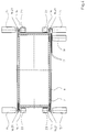
Figur 1- in einer Seitenansicht das Prinzip einer Schlauchbeutelmaschine zur Erzeugung eines Schlauchbeutels mit einer asymmetrischen Formschulter zur Umformung einer ebenen Folienbahn zu einem Folienschlauch, einem verjüngten Füllrohr, flachen Spreizelementen, geschlossenen, umlaufenden Backen einer Querschweisseinrichtung, mit gegen die ausgelenkten Schlauchränder gerichteten Kantenschweisseinrichtungen, sowie einer separaten Längsschweisseinrichtung;
Figur 2- in einem Schnitt entlang AA der
Figur 1 das Füllrohr mit vier Folienspreizern und jeweils einem Folienrückhalter zwischen zwei Folienspreizern; Figur 3- in einem Schnitt entlang BB der
Figur 2 das Füllrohr mit vier Spreizelementen, jeweils einer Kantenschweisseinrichtung pro Spreizelement, sowie einer separaten, zusätzlichen Längsschweisseinrichtung am Schlauchrand; Figur 4- in einem Schnitt einen Gegenstand
analog Figur 3, jedoch mit umgelegtem Schlauchrand und versetzter, abgeänderter Längsschweisseinrichtung; Figur 5- in einer perspektivischen Darstellung einen Schlauchbeutel mit jeweils zwei Seitenfalten pro Seite und mit an jeweils den beiden Rändern der beiden Seiten vorgesehenen, parallel zu einer Längsnaht verlaufenden verschweissten Kanten, sowie
Figur 6- in einer perspektivischen Darstellung einen Schlauchbeutel
analog Figur 5, jedoch mit einem umgeklappten Randbereich des Beutels.
- Figure 1
- In a side view, the principle of a tubular bag machine for producing a tubular bag with an asymmetrical shape shoulder for forming a flat film web into a film tube, a tapered filling tube, flat expansion elements, closed, circumferential jaws of a cross-welding device, with edge welding devices directed against the deflected tube edges, and a separate longitudinal welding device ;
- Figure 2
- in a section along AA of Figure 1, the fill tube with four film spreaders and one film retainer between two film spreaders;
- Figure 3
- in a section along BB of Figure 2, the filling tube with four expansion elements, one edge welding device per expansion element, and a separate, additional longitudinal welding device on the edge of the hose;
- Figure 4
- in a section an object analogous to FIG. 3, but with the hose edge folded over and offset, modified longitudinal welding device;
- Figure 5
- in a perspective view, a tubular bag with two side gussets per side and with welded edges provided on each of the two edges of the two sides and running parallel to a longitudinal seam, and
- Figure 6
- a perspective view of a tubular bag analogous to Figure 5, but with a folded edge region of the bag.
Bei einer vertikalen Schlauchbeutelmaschine 1 wird eine ebene Folienbahn 2 von einer
Vorratsrolle 3 abgewickelt und über eine Umlenkrolle 4 einer asymmetrischen
Formschulter 5 zugeführt (Figur 1). Die Kragen-Brustteile 34, 35 der Formschulter 5
sind verschieden lang. Ein Folienabzug 6 dient dem Weitertransport der Folienbahn 2.
Ein Füllrohr 7 nimmt die zu einem Folienschlauch 8 geformte Folienbahn 2 auf.
Gegeneinander bewegliche Backen 9 einer Querschweisseinrichtung 10 dienen der
Erzeugung von Quernähten 11 am Folienschlauch 8. In einer der Backen 9 befindet
sich eine Trenneinrichtung 12 zur Durchtrennung des Folienschlauches 8 zwischen
jeweils zwei Quernähten 11. Durch das Füllrohr 7 erfolgt eine Befüllung der erzeugten
Beutel 13.In the case of a vertical
Mit dem Füllrohr 7 sind vier vom Füllrohr 7 weg weisende, flache Spreizelemente 14
verbunden (Figuren 3). In Folientransportrichtung den Spreizelementen 14
nachgeordnet, d. h. unterhalb der Spreizelemente 14, ist jeweils eine
Kantenschweisseinrichtung 15 pro Spreizelement 14 vorgesehen, die jeweils gegen
von einem Spreizelement 14 ausgelenkten Schlauchrand 16 gerichtet ist.With the filling
Die Formschulter 7 versetzt die aufeinander liegenden Folienränder 17 nach rechts an
die Seite des Folienschlauches 8. Eine separate Längsschweisseinrichtung 18 ist für
eine Verschweissung des dem Schlauchrand 16 benachbarten Bereichs 19
vorgesehen, um zwei direkt nebeneinander liegende Schweissnähte zu erzeugen. Die
Längsschweisseinrichtung 18 erzeugt eine Längsnaht 20, wohingegen jede
Kantenschweisseinrichtung 15 eine verschweisste Kante 21 am Folienschlauch 8
erzeugt. Die Längsschweisseinrichtung 18 ist gegenüber der ihr benachbarten
Kantenschweisseinrichtung 15 zum Folienrand 17 hin versetzt. Der Folienrand 17 weist
in Form einer Flosse 22 vom Folienschlauch 8 weg.The
Der Folienabzug 6 wird kontinuierlich betrieben. Die Längsschweisseinrichtung 18 und
die Kantenschweisseinrichtungen 15 sind kontinuierlich angetriebene, umlaufende
Siegelbänder. Die Kantenschweisseinrichtungen 15 weisen jeweils einen Gegenhalter
23 auf. The film take-
An der Querschweisseinrichtung 10 sind zwei Paar 24, 25 Seitenfaltenerzeuger 26
vorgesehen. Die beiden Seitenfaltenerzeuger 26 eines Paars 24, 25 sind
gegeneinander und in den zwischen ihnen befindlichen Folienschlauch 8 bewegbar,
um Seitenfalten im Beutel 13 zu erzeugen. Ein Paar 24 ist in Folientransportrichtung
vor und ein Paar 25 nach der Querschweisseinrichtung 10 vorgesehen. Der Abstand
27 des einen Paars 24 von der Querschweisseinrichtung 10 ist, in
Folientransportrichtung gesehen, gleich dem Abstand 27 des anderen Paars 25 von
der Querschweisseinrichtung 10.There are two
Die Formschulter 5 weist einen seitlichen Schlitz 28 auf, durch den der Folienrand 17
herausgeführt wird (Figur 1). Im Bereich der Formschulter 5 sind zwei Folienrückhalter
29 am Füllrohr 7 vorgesehen, die jeweils zwischen zwei Folienspreizern 30 angeordnet
sind, um den Folienschlauch 8 für eine Verschweissung der Kanten 21 vorzuformen.The
An der ebenen Folienbahn 2 ist eine Einrichtung 31 zum Anbringen einer
Beutelöffnungshilfe 32 angebracht (Figur 1). Die Beutelöffnungshilfe 32 ist eine
streifenförmige Peelschicht, die in die Längsnaht 20 einläuft und dazu dient, einen
derart erzeugten Beutel 13 (Figur 5) leichter öffnen zu können.On the
Der Beutel 13 weist vier Seitenfalten 33 auf und ist kopfseitig und bodenseitig mittels
jeweils einer Quernaht 11 verschlossen. Neben einer seiner vier verschweissten
Kanten 21 verläuft seine Längsnaht 20. Seine Flosse 22 steht vom Beutel 13 ab. Die
Peelschicht innerhalb der Längsnaht 20 ermöglicht ein einfaches Öffnen der
Längsnaht 20 durch Aufziehen.The
Mittels einer Anordnung der Längsschweisseinrichtung 18 gemäss Figur 4 kann ein
Beutel 13 gemäss Figur 6 erzeugt werden. Die Längsschweisseinrichtung 18 wirkt hier
gegen die umgelegte Flosse 22 und gegen das Füllrohr 7. Der entsprechende Beutel
13 weist somit eine umgelegte Längsnaht 20 auf.An arrangement of the
Die erzeugten Beutel 13 (Figur 5, Figur 6) können auf die Kanten 21 gestellt werden, an denen die Längsnaht 20 nicht vorkommt. Dann kann die oben liegende Längsnaht 20 geöffnet werden, um Produkt aus dem Beutel 13 zu entnehmen. Die Kanten 21 stabilisieren den Beutel 13. Es könnte auch die an der Längsnaht 20 angrenzende Kante 21 dicht verschlossen sein und in der Längsnaht 20 könnte sich ein doppelseitig klebender Klebestreifen oder ein Zipp-Wiederverschlussstreifen befinden, um eine einfache Wiederverschliessung des Beutels 13 zu erreichen. Alternativ dazu kann auch die Längsnaht 20 fest verschweisst werden und die benachbarte Kante 21 mit einer Wiederverschliesshilfe versehen werden. Dazu müsste dann die Einrichtung 31 ein wenig zur Mitte 36 der Folienbahn 2 versetzt werden.
- 1
- Schlauchbeutelmaschine
- 2
- Folienbahn
- 3
- Vorratsrolle
- 4
- Umlenkrolle
- 5
- Formschulter
- 6
- Folienabzug
- 7
- Füllrohr
- 8
- Folienschlauch
- 9
- Backe
- 10
- Querschweisseinrichtung
- 11
- Quernaht
- 12
- Trenneinrichtung
- 13
- Beutel
- 14
- Spreizelement
- 15
- Kantenschweisseinrichtung
- 16
- Schlauchrand
- 17
- Folienrand
- 18
- Längsschweisseinrichtung
- 19
- Bereich
- 20
- Längsnaht
- 21
- verschweisste Kante
- 22
- Flosse
- 23
- Gegenhalter
- 24, 25
- Paar
- 26
- Seitenfaltenerzeuger
- 27
- Abstand
- 28
- Schlitz
- 29
- Folienrückhalter
- 30
- Folienspreizer
- 31
- Einrichtung zum Anbringen
- 32
- Beutelöffnungshilfe
- 33
- Seitenfalte
- 34, 35
- Kragen-Brustteil
- 36
Mitte der Folienbahn 2
- 1
- Tubular bag machine
- 2
- Foil web
- 3rd
- Supply roll
- 4th
- Pulley
- 5
- Shape shoulder
- 6
- Film deduction
- 7
- Filling pipe
- 8th
- Foil tube
- 9
- jaw
- 10
- Cross welding device
- 11
- Cross seam
- 12th
- Separator
- 13
- bag
- 14
- Expansion element
- 15
- Edge welding device
- 16
- Hose edge
- 17th
- Foil edge
- 18th
- Longitudinal welding device
- 19th
- Area
- 20th
- Longitudinal seam
- 21
- welded edge
- 22
- fin
- 23
- Counterhold
- 24, 25
- Pair
- 26
- Gusset generator
- 27
- distance
- 28
- slot
- 29
- Foil retainer
- 30th
- Foil spreader
- 31
- Attachment device
- 32
- Bag opening aid
- 33
- Gusset
- 34, 35
- Collar chest part
- 36
- Center of the
film web 2
Claims (13)
Priority Applications (2)
| Application Number | Priority Date | Filing Date | Title |
|---|---|---|---|
| EP04014687A EP1464578B1 (en) | 1999-12-01 | 2000-11-23 | Machine for making tubular bags |
| EP04014688A EP1462364B2 (en) | 1999-12-01 | 2000-11-23 | Machine for making tubular bags |
Applications Claiming Priority (2)
| Application Number | Priority Date | Filing Date | Title |
|---|---|---|---|
| DE19957891 | 1999-12-01 | ||
| DE19957891A DE19957891A1 (en) | 1999-12-01 | 1999-12-01 | Tubular bag machine |
Related Child Applications (2)
| Application Number | Title | Priority Date | Filing Date |
|---|---|---|---|
| EP04014687A Division EP1464578B1 (en) | 1999-12-01 | 2000-11-23 | Machine for making tubular bags |
| EP04014688A Division EP1462364B2 (en) | 1999-12-01 | 2000-11-23 | Machine for making tubular bags |
Publications (2)
| Publication Number | Publication Date |
|---|---|
| EP1106508A1 true EP1106508A1 (en) | 2001-06-13 |
| EP1106508B1 EP1106508B1 (en) | 2004-09-08 |
Family
ID=7931038
Family Applications (3)
| Application Number | Title | Priority Date | Filing Date |
|---|---|---|---|
| EP04014688A Expired - Lifetime EP1462364B2 (en) | 1999-12-01 | 2000-11-23 | Machine for making tubular bags |
| EP00125666A Revoked EP1106508B1 (en) | 1999-12-01 | 2000-11-23 | Machine for making tubular bags |
| EP04014687A Revoked EP1464578B1 (en) | 1999-12-01 | 2000-11-23 | Machine for making tubular bags |
Family Applications Before (1)
| Application Number | Title | Priority Date | Filing Date |
|---|---|---|---|
| EP04014688A Expired - Lifetime EP1462364B2 (en) | 1999-12-01 | 2000-11-23 | Machine for making tubular bags |
Family Applications After (1)
| Application Number | Title | Priority Date | Filing Date |
|---|---|---|---|
| EP04014687A Revoked EP1464578B1 (en) | 1999-12-01 | 2000-11-23 | Machine for making tubular bags |
Country Status (5)
| Country | Link |
|---|---|
| US (1) | US6729112B2 (en) |
| EP (3) | EP1462364B2 (en) |
| AT (3) | ATE306420T1 (en) |
| DE (4) | DE19957891A1 (en) |
| ES (3) | ES2250945T5 (en) |
Cited By (46)
| Publication number | Priority date | Publication date | Assignee | Title |
|---|---|---|---|---|
| WO2004110885A1 (en) | 2003-06-19 | 2004-12-23 | Aroma System Srl | Package with reinforced edges and pouring device |
| WO2005025993A1 (en) * | 2003-09-12 | 2005-03-24 | Cfs Weert B.V. | Packaging machine, especially vertical-type packaging machine, and method |
| EP1544107A1 (en) * | 2003-12-17 | 2005-06-22 | Rovema Verpackungsmaschinen GmbH | Vertical form fill and seal machine for producing flat self-standing pouches |
| WO2009021156A2 (en) * | 2007-08-08 | 2009-02-12 | Clear Lam Packaging, Inc. | Flexible, stackable container and method and system for manufacturing same |
| WO2009061959A1 (en) | 2007-11-09 | 2009-05-14 | Clear Lam Packaging, Inc. | Flexible, stackable container and method and system for manufacturing same |
| ITTV20090118A1 (en) * | 2009-06-05 | 2010-12-06 | Md Bag Forming Sets Srl | PACKAGE WITH ADDITIONAL POCKET WELDED ON ALL SIDES FOR FOODSTUFFS, EQUIPMENT FOR ITS PRODUCTION AND PROCEDURE FOR OBTAINING THE PACKAGE |
| WO2012175234A1 (en) * | 2011-06-21 | 2012-12-27 | Huhtamaki Ronsberg, Zweigniederlassung Der Huhtamaki Deutschland Gmbh & Co. Kg | Flow-pack packaging, especially flow-wrap packaging, and a blank for producing a flow-wrap packaging |
| US8602244B2 (en) | 2007-08-08 | 2013-12-10 | Clear Lam Packaging, Inc. | Flexible, stackable sealed package having corner seals and formed from a sheet of film |
| USD715643S1 (en) | 2013-07-30 | 2014-10-21 | Clear Lam Packaging, Inc. | Package |
| USD725467S1 (en) | 2013-07-30 | 2015-03-31 | Clear Lam Packaging, Inc. | Package |
| USD726535S1 (en) | 2013-07-30 | 2015-04-14 | Clear Lam Packaging, Inc. | Package |
| USD730725S1 (en) | 2014-03-07 | 2015-06-02 | Clear Lam Packaging, Inc. | Package |
| USD733549S1 (en) | 2013-10-25 | 2015-07-07 | Clear Lam Packaging, Inc. | Package |
| USD734144S1 (en) | 2014-05-30 | 2015-07-14 | Clear Lam Packaging, Inc. | Package |
| USD739232S1 (en) | 2013-07-30 | 2015-09-22 | Clear Lam Packaging, Inc. | Film used to make packages |
| USD740114S1 (en) | 2014-03-07 | 2015-10-06 | Clear Lam Packaging, Inc. | Package |
| USD746673S1 (en) | 2014-06-20 | 2016-01-05 | Clear Lam Packaging, Inc. | Package |
| USD747202S1 (en) | 2014-02-28 | 2016-01-12 | Clear Lam Packaging, Inc. | Film used to make packages |
| USD747195S1 (en) | 2014-02-14 | 2016-01-12 | Clear Lam Packaging, Inc. | Film for packaging production |
| USD747189S1 (en) | 2013-09-09 | 2016-01-12 | Clear Lam Packaging, Inc. | Package |
| USD747646S1 (en) | 2014-06-20 | 2016-01-19 | Clear Lam Packaging, Inc. | Package |
| USD748471S1 (en) | 2014-02-14 | 2016-02-02 | Clear Lam Packaging, Inc. | Film for packaging production |
| USD750477S1 (en) | 2014-03-07 | 2016-03-01 | Clear Lam Packaging, Inc. | Package |
| EP3006349A1 (en) * | 2011-01-11 | 2016-04-13 | Rovipak Packaging Solutions Limited | Packaging system |
| USD753996S1 (en) | 2014-03-26 | 2016-04-19 | Clear Lam Packaging, Inc. | Package |
| USD753995S1 (en) | 2014-03-07 | 2016-04-19 | Clear Lam Packaging, Inc. | Film for packaging production |
| USD754534S1 (en) | 2014-09-25 | 2016-04-26 | Clear Lam Packaging, Inc. | Package |
| USD756219S1 (en) | 2014-10-31 | 2016-05-17 | Clear Lam Packaging, Inc. | Package |
| USD761651S1 (en) | 2014-01-28 | 2016-07-19 | Clear Lam Packaging, Inc. | Package |
| USD764914S1 (en) | 2013-11-12 | 2016-08-30 | Clear Lam Packaging, Inc. | Package |
| USD766082S1 (en) | 2014-02-28 | 2016-09-13 | Clear Lam Packaging, Inc. | Package |
| USD768479S1 (en) | 2014-01-16 | 2016-10-11 | Clear Lam Packaging, Inc. | Package |
| USD772069S1 (en) | 2014-09-25 | 2016-11-22 | Clear Lam Packaging, Inc. | Film for making packages |
| USD777026S1 (en) | 2013-11-12 | 2017-01-24 | Clear Lam Packaging, Inc. | Package |
| USD778719S1 (en) | 2014-10-15 | 2017-02-14 | Clear Lam Packaging, Inc. | Package |
| USD781702S1 (en) | 2014-08-25 | 2017-03-21 | Clear Lam Packaging, Inc. | Material for packaging production |
| USD784127S1 (en) | 2014-10-31 | 2017-04-18 | Clear Lam Packaging, Inc. | Film for packaging production |
| USD787319S1 (en) | 2014-11-17 | 2017-05-23 | Clear Lam Packaging, Inc. | Package |
| USD788582S1 (en) | 2014-10-31 | 2017-06-06 | Clear Lam Packaging, Inc. | Film for packaging production |
| US9745104B2 (en) | 2012-10-26 | 2017-08-29 | Clear Lam Packaging, Inc. | Flexible stackable package |
| IT201600092666A1 (en) * | 2016-09-14 | 2018-03-14 | Cavanna Spa | PROCEDURE AND EQUIPMENT FOR PRODUCT PACKAGING |
| USD813663S1 (en) | 2014-03-13 | 2018-03-27 | Primapak, Llc | Package |
| US10207850B2 (en) | 2012-10-26 | 2019-02-19 | Primapak, Llc. | Flexible package and method of making same |
| US10843837B2 (en) | 2015-09-18 | 2020-11-24 | Primapak, Llc | Apparatus and method for making a flexible package |
| US10994882B2 (en) | 2014-05-19 | 2021-05-04 | Primapak, Llc | Apparatus and method for making a flexible package |
| EP3851271A1 (en) * | 2020-01-14 | 2021-07-21 | Windmöller & Hölscher KG | Method and device for the production of individual inner tubes and inner tubes and bags |
Families Citing this family (38)
| Publication number | Priority date | Publication date | Assignee | Title |
|---|---|---|---|---|
| DE10149476A1 (en) * | 2001-10-08 | 2003-04-17 | Rovema Gmbh | Tubular bag machine for producing edge-welded tubular bags |
| ITBO20020694A1 (en) * | 2002-11-04 | 2004-05-05 | Ica Spa | EQUIPMENT FOR PACKAGING BAGS |
| NL1026499C2 (en) * | 2003-01-06 | 2005-10-11 | Cfs Weert Bv | Form-fill-seal machine for making bag-shaped packaging, has longitudinal sealing station positioned at one lateral side of form tube for forming severable longitudinal seal at location of overlap |
| NL1023151C2 (en) * | 2003-01-06 | 2004-07-07 | C F S Weert B V | Device and method for manufacturing resealable packages. |
| US7003929B2 (en) * | 2003-07-25 | 2006-02-28 | Kraft Foods Holdings, Inc. | Apparatus and method for automated forming of sleeves for sliced products |
| EP1510461A1 (en) * | 2003-08-25 | 2005-03-02 | CFS Weert B.V. | Tubular bagging machine |
| ITMI20040312U1 (en) * | 2004-06-24 | 2004-09-24 | Ilapak Res & Developments Sa | WRAPPING MACHINE FOR THE FORMATION OF ENVELOPES WITH SIDE SHAPING EDGES |
| ITTV20040074A1 (en) * | 2004-06-29 | 2004-09-29 | Md Bag Forming Sets S R L | EQUIPMENT FOR FORMING A TUBULAR BAG, ESPECIALLY FOR THE PACKAGING OF PRODUCTS IN PACKAGING OF THE TYPE WITH CORNERS REINFORCED BY WELDING. |
| DE102004035581A1 (en) * | 2004-07-22 | 2006-02-16 | Rovema Verpackungsmaschinen Gmbh | Longitudinal weld forming device for tubes has heat sealer and seal tape in between which longitudinal weld is clamped to heat weld on opposing sides |
| US20060068200A1 (en) * | 2004-09-24 | 2006-03-30 | Cleckner Michael D | Surface-treated multi-layered polymer film |
| GB2421013B (en) * | 2004-12-10 | 2007-07-11 | Amcor Flexibles Europe As | Packaging with an openable top wall |
| DE102004062025A1 (en) * | 2004-12-23 | 2006-07-13 | Robert Bosch Gmbh | Device for producing hoses from a flat film |
| DE602005011572D1 (en) * | 2005-04-15 | 2009-01-22 | Regath Hb | Flexible packaging and process for its production |
| EP1792838A1 (en) * | 2005-11-30 | 2007-06-06 | CFS Weert B.V. | Envelope-shaped packaging bag |
| DE102006008587A1 (en) * | 2006-02-24 | 2007-08-30 | Rovema - Verpackungsmaschinen Gmbh | Bag making machine has side fold producer with heater, one or two sealing surfaces, edge welding device with one or two sealing surfaces for pressing tube edge(s) against sealing surface(s) of side fold producer for welding |
| DE102006010139A1 (en) * | 2006-03-06 | 2007-09-13 | Rovema - Verpackungsmaschinen Gmbh | Tubular bag machine for producing bag e.g. beverage bag, has edges welding devices including sealing surfaces, of which one sealing surface which is provided for head seam is outlined |
| US20080110133A1 (en) * | 2006-08-16 | 2008-05-15 | Lorenzi Thomas E | Flexible Container Filling Device |
| DE102006044914A1 (en) * | 2006-09-22 | 2008-04-03 | Rovema - Verpackungsmaschinen Gmbh | Bag making machine with continuously moving film strip has edge welding devices at same height as film pull-out with sealing elements and counter elements |
| DE102006046123B4 (en) * | 2006-09-28 | 2019-04-04 | Rovema Gmbh | Fill and seal machine |
| DE102006048284A1 (en) * | 2006-10-12 | 2008-04-17 | Rovema Verpackungsmaschinen Gmbh | Bag forming, filling and sealing machine, has foil support holding deflection unit opposite to film tube within region between two spreading units, and comprising recess in which foil extractor is placed |
| DE102006059003B4 (en) * | 2006-12-14 | 2014-07-17 | Rovema Gmbh | Fill and seal machine |
| US7987655B2 (en) | 2008-04-22 | 2011-08-02 | Rovema Packaging Machines, Lp | Tubular bagging machine and method |
| NL1035429C2 (en) * | 2008-05-16 | 2009-11-17 | Pmb Uva Internat B V | Device for packaging products in a foil package. |
| EP2156947A1 (en) | 2008-08-18 | 2010-02-24 | Ludger Fuest | Composite material and method for manufacturing a filled tubular bag |
| EP2376338A4 (en) * | 2008-11-06 | 2012-12-26 | Clear Lam Packaging Inc | Flexible, stackable container and method and system for manufacturing same |
| DE102009029357A1 (en) * | 2009-09-10 | 2011-03-24 | Robert Bosch Gmbh | Method for producing a packaging bag made of flexible film material and such a packaging bag |
| JP5476107B2 (en) * | 2009-12-07 | 2014-04-23 | 株式会社イシダ | Bag making and packaging machine |
| US8784289B2 (en) * | 2010-04-29 | 2014-07-22 | Illinois Tool Works Inc. | Process of forming a wide mouth gusseted bag with edge seals |
| JP5887694B2 (en) * | 2011-01-26 | 2016-03-16 | 凸版印刷株式会社 | Method for manufacturing a horizontal gusset bag with an opening at the top |
| DE202011002178U1 (en) | 2011-02-01 | 2012-05-03 | Teepack Spezialmaschinen Gmbh & Co. Kg | Packaging Unit |
| WO2015138651A1 (en) * | 2014-03-11 | 2015-09-17 | Clear Lam Packaging, Inc. | Apparatus and method to form edges in a package made of flexible material |
| DE202015009407U1 (en) | 2015-01-20 | 2017-06-30 | Robert Bosch Gmbh | Device for sealing a packaging or packaging material |
| CZ31260U1 (en) * | 2016-11-21 | 2017-12-04 | Viking Mašek, a.s. | A packing machine for creating and filling multiple types of bags |
| US11299333B2 (en) | 2017-04-04 | 2022-04-12 | The Procter & Gamble Company | Flexible packages with flat panels |
| EP3630636A1 (en) | 2017-05-24 | 2020-04-08 | The Procter and Gamble Company | Flexible packages with flat panels |
| CN110603201B (en) * | 2017-05-26 | 2021-12-03 | 宝洁公司 | Method of self-folding flexible packaging |
| EP3630646B1 (en) | 2017-05-26 | 2021-08-25 | The Procter & Gamble Company | Flexible packages with self-folding |
| EP3950514A1 (en) * | 2020-08-06 | 2022-02-09 | Ocm S.R.L. | Bagging machine |
Citations (2)
| Publication number | Priority date | Publication date | Assignee | Title |
|---|---|---|---|---|
| EP0627355A1 (en) * | 1992-02-10 | 1994-12-07 | Rovema Verpackungsmaschinen GmbH | Tubular bag and process and apparatus for making it |
| IT1274100B (en) | 1994-11-09 | 1997-07-15 | Ica Spa Soc | Flexible bag made of heat-sealable materials with hard corners |
Family Cites Families (13)
| Publication number | Priority date | Publication date | Assignee | Title |
|---|---|---|---|---|
| US2899875A (en) * | 1959-08-18 | leasure | ||
| US1986422A (en) * | 1933-11-28 | 1935-01-01 | Transparent Wrap Machine Corp | Automatic packaging machine |
| US3091902A (en) * | 1959-04-17 | 1963-06-04 | Fr Hesser Maschinenfabrik Ag F | Method and device for fabricating bag packages |
| CH439065A (en) * | 1966-09-14 | 1967-06-30 | Sig Schweiz Industrieges | Filled flat pouch, process for its production and device for carrying out the process |
| US3785112A (en) * | 1971-09-21 | 1974-01-15 | Mira Pak Inc | Method and apparatus for forming shaped package |
| US3807118A (en) † | 1972-03-31 | 1974-04-30 | Schneider W | Method of forming a package |
| DE2337216A1 (en) * | 1973-07-21 | 1975-02-06 | Mira Pak Inc | METHOD OF MANUFACTURING POUCHPACKS AND DEVICE FOR CARRYING OUT THE METHOD |
| US4442656A (en) * | 1981-10-26 | 1984-04-17 | Universal Packaging, Inc. | Filling and sealing machine for providing a flat bottom package |
| US4709533A (en) * | 1986-12-22 | 1987-12-01 | Minigrip, Inc. | Method and apparatus for making reclosable bags in a form, fill and seal machine |
| US5417035A (en) * | 1988-09-06 | 1995-05-23 | Kcl Corporation | Apparatus and method for manufacture flexible reclosable containers |
| US5758473A (en) * | 1993-11-05 | 1998-06-02 | Patelli; Ferruccio | Method for manufacturing packages for liquid products, especially liquid foodstuffs and a package obtained through this method |
| DE19603371B4 (en) * | 1996-01-31 | 2006-12-14 | Rovema - Verpackungsmaschinen Gmbh | Tubular bag machine with an asymmetric forming shoulder for the production of tubular bags |
| US5862652A (en) * | 1995-03-03 | 1999-01-26 | Rovema Packaging Machines, L.P. | Tubular bagging machine with an asymmetrical forming shoulder and tubular bags with an edge-side longitudinal seam |
-
1999
- 1999-12-01 DE DE19957891A patent/DE19957891A1/en not_active Withdrawn
-
2000
- 2000-11-23 ES ES04014688T patent/ES2250945T5/en not_active Expired - Lifetime
- 2000-11-23 EP EP04014688A patent/EP1462364B2/en not_active Expired - Lifetime
- 2000-11-23 DE DE50010650T patent/DE50010650D1/en not_active Revoked
- 2000-11-23 ES ES04014687T patent/ES2242176T3/en not_active Expired - Lifetime
- 2000-11-23 AT AT04014688T patent/ATE306420T1/en not_active IP Right Cessation
- 2000-11-23 EP EP00125666A patent/EP1106508B1/en not_active Revoked
- 2000-11-23 ES ES00125666T patent/ES2228384T3/en not_active Expired - Lifetime
- 2000-11-23 EP EP04014687A patent/EP1464578B1/en not_active Revoked
- 2000-11-23 DE DE50011347T patent/DE50011347D1/en not_active Expired - Lifetime
- 2000-11-23 DE DE50007676T patent/DE50007676D1/en not_active Revoked
- 2000-11-23 AT AT00125666T patent/ATE275499T1/en not_active IP Right Cessation
- 2000-11-23 AT AT04014687T patent/ATE298703T1/en not_active IP Right Cessation
- 2000-11-30 US US09/726,264 patent/US6729112B2/en not_active Expired - Lifetime
Patent Citations (2)
| Publication number | Priority date | Publication date | Assignee | Title |
|---|---|---|---|---|
| EP0627355A1 (en) * | 1992-02-10 | 1994-12-07 | Rovema Verpackungsmaschinen GmbH | Tubular bag and process and apparatus for making it |
| IT1274100B (en) | 1994-11-09 | 1997-07-15 | Ica Spa Soc | Flexible bag made of heat-sealable materials with hard corners |
Non-Patent Citations (5)
| Title |
|---|
| "Bags/pouches flex performance strenght", PACKING DIGEST, March 1988 (1988-03-01), pages 54 - 56, XP002950062 |
| "Dupont awards", PACKAGING DIGEST, October 1998 (1998-10-01), pages 132, XP002950064 |
| "Ore-idea's new recipe for bagmaking", PACKAGING DIGEST, January 2001 (2001-01-01), pages 38 - 42, XP002950065 |
| "Pouching technologies make global gaines", PACKAGING DIGEST, November 1996 (1996-11-01), pages 68 - 69, XP002950063 |
| REINER T. UND ROSE D.: "Die Folienschachtel", VERPACKUNGS-RUNDSCHAU, August 1996 (1996-08-01), pages 8 - 9, XP002950061 |
Cited By (60)
| Publication number | Priority date | Publication date | Assignee | Title |
|---|---|---|---|---|
| WO2004110885A1 (en) | 2003-06-19 | 2004-12-23 | Aroma System Srl | Package with reinforced edges and pouring device |
| WO2005025993A1 (en) * | 2003-09-12 | 2005-03-24 | Cfs Weert B.V. | Packaging machine, especially vertical-type packaging machine, and method |
| EP1544107A1 (en) * | 2003-12-17 | 2005-06-22 | Rovema Verpackungsmaschinen GmbH | Vertical form fill and seal machine for producing flat self-standing pouches |
| US8602244B2 (en) | 2007-08-08 | 2013-12-10 | Clear Lam Packaging, Inc. | Flexible, stackable sealed package having corner seals and formed from a sheet of film |
| WO2009021156A3 (en) * | 2007-08-08 | 2009-04-23 | Clear Lam Packaging Inc | Flexible, stackable container and method and system for manufacturing same |
| EP3109183A1 (en) * | 2007-08-08 | 2016-12-28 | Clear Lam Packaging, Inc. | Flexible, stackable container and method for manufacturing same |
| US9162786B2 (en) | 2007-08-08 | 2015-10-20 | Clear Lam Packaging, Inc. | Flexible, stackable container and method and system for manufacturing the same |
| US10023337B2 (en) | 2007-08-08 | 2018-07-17 | Primapak, Llc | Flexible, stackable container and method and system for manufacturing the same |
| US10232969B2 (en) | 2007-08-08 | 2019-03-19 | Primapak, Llc. | Flexible, stackable container and method and system for manufacturing the same |
| US11124323B2 (en) | 2007-08-08 | 2021-09-21 | Primapak, Llc | Flexible, stackable container and method and system for manufacturing the same |
| WO2009021156A2 (en) * | 2007-08-08 | 2009-02-12 | Clear Lam Packaging, Inc. | Flexible, stackable container and method and system for manufacturing same |
| WO2009061959A1 (en) | 2007-11-09 | 2009-05-14 | Clear Lam Packaging, Inc. | Flexible, stackable container and method and system for manufacturing same |
| EP2214978A1 (en) * | 2007-11-09 | 2010-08-11 | Clear Lam Packaging, Inc. | Flexible, stackable container and method and system for manufacturing same |
| EP2214978A4 (en) * | 2007-11-09 | 2014-03-26 | Clear Lam Packaging Inc | Flexible, stackable container and method and system for manufacturing same |
| ITTV20090118A1 (en) * | 2009-06-05 | 2010-12-06 | Md Bag Forming Sets Srl | PACKAGE WITH ADDITIONAL POCKET WELDED ON ALL SIDES FOR FOODSTUFFS, EQUIPMENT FOR ITS PRODUCTION AND PROCEDURE FOR OBTAINING THE PACKAGE |
| EP3006349A1 (en) * | 2011-01-11 | 2016-04-13 | Rovipak Packaging Solutions Limited | Packaging system |
| WO2012175234A1 (en) * | 2011-06-21 | 2012-12-27 | Huhtamaki Ronsberg, Zweigniederlassung Der Huhtamaki Deutschland Gmbh & Co. Kg | Flow-pack packaging, especially flow-wrap packaging, and a blank for producing a flow-wrap packaging |
| US9850036B2 (en) | 2012-10-26 | 2017-12-26 | Clear Lam Packaging, Inc. | Flexible package and method of making the same |
| US10207850B2 (en) | 2012-10-26 | 2019-02-19 | Primapak, Llc. | Flexible package and method of making same |
| US9745104B2 (en) | 2012-10-26 | 2017-08-29 | Clear Lam Packaging, Inc. | Flexible stackable package |
| US10532855B2 (en) | 2012-10-26 | 2020-01-14 | Primapak, Llc | Flexible material for flexible package |
| US11267632B2 (en) | 2012-10-26 | 2022-03-08 | Primapak, Llc | Flexible package and method of making the same |
| US10399746B2 (en) | 2012-10-26 | 2019-09-03 | Primapak, Llc | Flexible material for flexible package |
| US11447299B2 (en) | 2012-10-26 | 2022-09-20 | Primapak, Llc | Flexible material for flexible package |
| USD715643S1 (en) | 2013-07-30 | 2014-10-21 | Clear Lam Packaging, Inc. | Package |
| USD739232S1 (en) | 2013-07-30 | 2015-09-22 | Clear Lam Packaging, Inc. | Film used to make packages |
| USD725467S1 (en) | 2013-07-30 | 2015-03-31 | Clear Lam Packaging, Inc. | Package |
| USD726535S1 (en) | 2013-07-30 | 2015-04-14 | Clear Lam Packaging, Inc. | Package |
| USD747189S1 (en) | 2013-09-09 | 2016-01-12 | Clear Lam Packaging, Inc. | Package |
| USD733549S1 (en) | 2013-10-25 | 2015-07-07 | Clear Lam Packaging, Inc. | Package |
| USD764914S1 (en) | 2013-11-12 | 2016-08-30 | Clear Lam Packaging, Inc. | Package |
| USD777026S1 (en) | 2013-11-12 | 2017-01-24 | Clear Lam Packaging, Inc. | Package |
| USD768479S1 (en) | 2014-01-16 | 2016-10-11 | Clear Lam Packaging, Inc. | Package |
| USD761651S1 (en) | 2014-01-28 | 2016-07-19 | Clear Lam Packaging, Inc. | Package |
| USD748471S1 (en) | 2014-02-14 | 2016-02-02 | Clear Lam Packaging, Inc. | Film for packaging production |
| USD747195S1 (en) | 2014-02-14 | 2016-01-12 | Clear Lam Packaging, Inc. | Film for packaging production |
| USD747202S1 (en) | 2014-02-28 | 2016-01-12 | Clear Lam Packaging, Inc. | Film used to make packages |
| USD766082S1 (en) | 2014-02-28 | 2016-09-13 | Clear Lam Packaging, Inc. | Package |
| USD730725S1 (en) | 2014-03-07 | 2015-06-02 | Clear Lam Packaging, Inc. | Package |
| USD753995S1 (en) | 2014-03-07 | 2016-04-19 | Clear Lam Packaging, Inc. | Film for packaging production |
| USD740114S1 (en) | 2014-03-07 | 2015-10-06 | Clear Lam Packaging, Inc. | Package |
| USD750477S1 (en) | 2014-03-07 | 2016-03-01 | Clear Lam Packaging, Inc. | Package |
| USD813663S1 (en) | 2014-03-13 | 2018-03-27 | Primapak, Llc | Package |
| USD753996S1 (en) | 2014-03-26 | 2016-04-19 | Clear Lam Packaging, Inc. | Package |
| US10994882B2 (en) | 2014-05-19 | 2021-05-04 | Primapak, Llc | Apparatus and method for making a flexible package |
| USD734144S1 (en) | 2014-05-30 | 2015-07-14 | Clear Lam Packaging, Inc. | Package |
| USD746673S1 (en) | 2014-06-20 | 2016-01-05 | Clear Lam Packaging, Inc. | Package |
| USD747646S1 (en) | 2014-06-20 | 2016-01-19 | Clear Lam Packaging, Inc. | Package |
| USD781702S1 (en) | 2014-08-25 | 2017-03-21 | Clear Lam Packaging, Inc. | Material for packaging production |
| USD754534S1 (en) | 2014-09-25 | 2016-04-26 | Clear Lam Packaging, Inc. | Package |
| USD772069S1 (en) | 2014-09-25 | 2016-11-22 | Clear Lam Packaging, Inc. | Film for making packages |
| USD778719S1 (en) | 2014-10-15 | 2017-02-14 | Clear Lam Packaging, Inc. | Package |
| USD756219S1 (en) | 2014-10-31 | 2016-05-17 | Clear Lam Packaging, Inc. | Package |
| USD788582S1 (en) | 2014-10-31 | 2017-06-06 | Clear Lam Packaging, Inc. | Film for packaging production |
| USD784127S1 (en) | 2014-10-31 | 2017-04-18 | Clear Lam Packaging, Inc. | Film for packaging production |
| USD787319S1 (en) | 2014-11-17 | 2017-05-23 | Clear Lam Packaging, Inc. | Package |
| US10843837B2 (en) | 2015-09-18 | 2020-11-24 | Primapak, Llc | Apparatus and method for making a flexible package |
| EP3296217A1 (en) * | 2016-09-14 | 2018-03-21 | Cavanna S.p.A. | A method and apparatus for packaging of products |
| IT201600092666A1 (en) * | 2016-09-14 | 2018-03-14 | Cavanna Spa | PROCEDURE AND EQUIPMENT FOR PRODUCT PACKAGING |
| EP3851271A1 (en) * | 2020-01-14 | 2021-07-21 | Windmöller & Hölscher KG | Method and device for the production of individual inner tubes and inner tubes and bags |
Also Published As
| Publication number | Publication date |
|---|---|
| US6729112B2 (en) | 2004-05-04 |
| EP1462364A1 (en) | 2004-09-29 |
| ES2250945T5 (en) | 2009-12-11 |
| EP1462364B2 (en) | 2009-07-22 |
| ATE306420T1 (en) | 2005-10-15 |
| DE19957891A1 (en) | 2001-06-07 |
| US20010005979A1 (en) | 2001-07-05 |
| EP1464578B1 (en) | 2005-06-29 |
| ES2250945T3 (en) | 2006-04-16 |
| ATE298703T1 (en) | 2005-07-15 |
| EP1462364B1 (en) | 2005-10-12 |
| DE50007676D1 (en) | 2004-10-14 |
| ATE275499T1 (en) | 2004-09-15 |
| EP1464578A1 (en) | 2004-10-06 |
| DE50011347D1 (en) | 2006-02-23 |
| EP1106508B1 (en) | 2004-09-08 |
| ES2228384T3 (en) | 2005-04-16 |
| DE50010650D1 (en) | 2005-08-04 |
| ES2242176T3 (en) | 2005-11-01 |
Similar Documents
| Publication | Publication Date | Title |
|---|---|---|
| EP1106508B1 (en) | Machine for making tubular bags | |
| DE69926942T2 (en) | Transverse zipper strip | |
| DE10017479A1 (en) | Vertical tubular bag machine and bag produced with it | |
| EP1077874B1 (en) | Device for producing re-sealable tubular packaging bags | |
| DE60026434T2 (en) | Manufacture of reclosable packaging using a transversal zipper | |
| DE2925440A1 (en) | MULTI-WALLY BAG AND METHOD AND DEVICE FOR PRODUCING A MULTI-WALLY BAG | |
| EP1060072A1 (en) | Device for producing film bags | |
| WO2007087965A1 (en) | Bag and method for producing the same | |
| CH627413A5 (en) | TUBE BAG MACHINE. | |
| WO2018060277A1 (en) | Plastic bag, in particular ffs bag, and method and device for producing and filling a bag | |
| EP2511187A2 (en) | Container for packing bulk material and method for processing a sheet of material | |
| EP0729886B1 (en) | Tubular bag-making machine with a gusset former | |
| EP2480458A1 (en) | Forming shoulder and device for producing tubular bags | |
| DE19538146A1 (en) | Pouch with at least one vent and method of making the pouch | |
| EP2998236B1 (en) | Side gusseted bag and method for producing a side gusseted bag | |
| DE1922826C3 (en) | A sack made from a tubular section made of thermoplastic plastic film with a cross-bottom fold, as well as a method and device for its production | |
| DE10251072A1 (en) | Form shoulder for forming a film web | |
| DE102006010139A1 (en) | Tubular bag machine for producing bag e.g. beverage bag, has edges welding devices including sealing surfaces, of which one sealing surface which is provided for head seam is outlined | |
| DE102006046123B4 (en) | Fill and seal machine | |
| DE102005018545A1 (en) | Method for production and filling of bags used in e.g. foodstuffs industry, involves supplying roll of hose-like material already added with slide fasteners and bag sidewalls to form, fill, and seal (FFS) machine | |
| DE102005018548A1 (en) | Process to produce repeatedly opening and closing bags or sacks with tube or tube section whereby means to open or close bags are put and fixed to cut on side of tube and hole thus created can be opened or closed | |
| DE10131902A1 (en) | Machine for making flat bottomed plastic bags has sealer which makes resealable closure, fingers which fold sides and sealing and pressing unit which forms pouring spout at top of bag | |
| DE10330294A1 (en) | Vertical flow wrap machine | |
| DE3616262C2 (en) | ||
| DE102005039937A1 (en) | Bag for use in packing industry, has packing material whose inner layer is welded with outer layer of film strip and whose outer layer is welded with another outer layer of strip, where welded portion can be pulled |
Legal Events
| Date | Code | Title | Description |
|---|---|---|---|
| PUAI | Public reference made under article 153(3) epc to a published international application that has entered the european phase |
Free format text: ORIGINAL CODE: 0009012 |
|
| 17P | Request for examination filed |
Effective date: 20001208 |
|
| AK | Designated contracting states |
Kind code of ref document: A1 Designated state(s): AT BE CH CY DE DK ES FI FR GB GR IE IT LI LU MC NL PT SE TR |
|
| AX | Request for extension of the european patent |
Free format text: AL;LT;LV;MK;RO;SI |
|
| AKX | Designation fees paid |
Free format text: AT BE CH CY DE DK ES FI FR GB GR IE IT LI LU MC NL PT SE TR |
|
| TPAD | Observations filed by third parties |
Free format text: ORIGINAL CODE: EPIDOS TIPA |
|
| 17Q | First examination report despatched |
Effective date: 20020618 |
|
| GRAP | Despatch of communication of intention to grant a patent |
Free format text: ORIGINAL CODE: EPIDOSNIGR1 |
|
| GRAS | Grant fee paid |
Free format text: ORIGINAL CODE: EPIDOSNIGR3 |
|
| GRAA | (expected) grant |
Free format text: ORIGINAL CODE: 0009210 |
|
| AK | Designated contracting states |
Kind code of ref document: B1 Designated state(s): AT BE CH CY DE DK ES FI FR GB GR IE IT LI LU MC NL PT SE TR |
|
| PG25 | Lapsed in a contracting state [announced via postgrant information from national office to epo] |
Ref country code: TR Free format text: LAPSE BECAUSE OF FAILURE TO SUBMIT A TRANSLATION OF THE DESCRIPTION OR TO PAY THE FEE WITHIN THE PRESCRIBED TIME-LIMIT Effective date: 20040908 Ref country code: FI Free format text: LAPSE BECAUSE OF FAILURE TO SUBMIT A TRANSLATION OF THE DESCRIPTION OR TO PAY THE FEE WITHIN THE PRESCRIBED TIME-LIMIT Effective date: 20040908 Ref country code: IE Free format text: LAPSE BECAUSE OF FAILURE TO SUBMIT A TRANSLATION OF THE DESCRIPTION OR TO PAY THE FEE WITHIN THE PRESCRIBED TIME-LIMIT Effective date: 20040908 Ref country code: CY Free format text: LAPSE BECAUSE OF FAILURE TO SUBMIT A TRANSLATION OF THE DESCRIPTION OR TO PAY THE FEE WITHIN THE PRESCRIBED TIME-LIMIT Effective date: 20040908 |
|
| REG | Reference to a national code |
Ref country code: GB Ref legal event code: FG4D Free format text: NOT ENGLISH |
|
| REG | Reference to a national code |
Ref country code: CH Ref legal event code: EP |
|
| REG | Reference to a national code |
Ref country code: IE Ref legal event code: FG4D Free format text: GERMAN |
|
| REF | Corresponds to: |
Ref document number: 50007676 Country of ref document: DE Date of ref document: 20041014 Kind code of ref document: P |
|
| PG25 | Lapsed in a contracting state [announced via postgrant information from national office to epo] |
Ref country code: LU Free format text: LAPSE BECAUSE OF NON-PAYMENT OF DUE FEES Effective date: 20041123 Ref country code: AT Free format text: LAPSE BECAUSE OF NON-PAYMENT OF DUE FEES Effective date: 20041123 |
|
| PG25 | Lapsed in a contracting state [announced via postgrant information from national office to epo] |
Ref country code: LI Free format text: LAPSE BECAUSE OF NON-PAYMENT OF DUE FEES Effective date: 20041130 Ref country code: CH Free format text: LAPSE BECAUSE OF NON-PAYMENT OF DUE FEES Effective date: 20041130 Ref country code: MC Free format text: LAPSE BECAUSE OF NON-PAYMENT OF DUE FEES Effective date: 20041130 |
|
| PG25 | Lapsed in a contracting state [announced via postgrant information from national office to epo] |
Ref country code: DK Free format text: LAPSE BECAUSE OF FAILURE TO SUBMIT A TRANSLATION OF THE DESCRIPTION OR TO PAY THE FEE WITHIN THE PRESCRIBED TIME-LIMIT Effective date: 20041208 Ref country code: GR Free format text: LAPSE BECAUSE OF FAILURE TO SUBMIT A TRANSLATION OF THE DESCRIPTION OR TO PAY THE FEE WITHIN THE PRESCRIBED TIME-LIMIT Effective date: 20041208 Ref country code: SE Free format text: LAPSE BECAUSE OF FAILURE TO SUBMIT A TRANSLATION OF THE DESCRIPTION OR TO PAY THE FEE WITHIN THE PRESCRIBED TIME-LIMIT Effective date: 20041208 |
|
| GBT | Gb: translation of ep patent filed (gb section 77(6)(a)/1977) |
Effective date: 20041130 |
|
| REG | Reference to a national code |
Ref country code: ES Ref legal event code: FG2A Ref document number: 2228384 Country of ref document: ES Kind code of ref document: T3 |
|
| REG | Reference to a national code |
Ref country code: IE Ref legal event code: FD4D |
|
| PLAQ | Examination of admissibility of opposition: information related to despatch of communication + time limit deleted |
Free format text: ORIGINAL CODE: EPIDOSDOPE2 |
|
| PLBQ | Unpublished change to opponent data |
Free format text: ORIGINAL CODE: EPIDOS OPPO |
|
| PLAQ | Examination of admissibility of opposition: information related to despatch of communication + time limit deleted |
Free format text: ORIGINAL CODE: EPIDOSDOPE2 |
|
| PLAR | Examination of admissibility of opposition: information related to receipt of reply deleted |
Free format text: ORIGINAL CODE: EPIDOSDOPE4 |
|
| PLBI | Opposition filed |
Free format text: ORIGINAL CODE: 0009260 |
|
| PLBQ | Unpublished change to opponent data |
Free format text: ORIGINAL CODE: EPIDOS OPPO |
|
| ET | Fr: translation filed | ||
| PLAX | Notice of opposition and request to file observation + time limit sent |
Free format text: ORIGINAL CODE: EPIDOSNOBS2 |
|
| REG | Reference to a national code |
Ref country code: CH Ref legal event code: PL |
|
| 26 | Opposition filed |
Opponent name: WOLF VERPACKUNGSMASCHINEN GMBH Effective date: 20050607 |
|
| NLR1 | Nl: opposition has been filed with the epo |
Opponent name: WOLF VERPACKUNGSMASCHINEN GMBH |
|
| PLAF | Information modified related to communication of a notice of opposition and request to file observations + time limit |
Free format text: ORIGINAL CODE: EPIDOSCOBS2 |
|
| PLBB | Reply of patent proprietor to notice(s) of opposition received |
Free format text: ORIGINAL CODE: EPIDOSNOBS3 |
|
| PLAY | Examination report in opposition despatched + time limit |
Free format text: ORIGINAL CODE: EPIDOSNORE2 |
|
| PLAH | Information related to despatch of examination report in opposition + time limit modified |
Free format text: ORIGINAL CODE: EPIDOSCORE2 |
|
| PLBC | Reply to examination report in opposition received |
Free format text: ORIGINAL CODE: EPIDOSNORE3 |
|
| PGFP | Annual fee paid to national office [announced via postgrant information from national office to epo] |
Ref country code: NL Payment date: 20061110 Year of fee payment: 7 |
|
| PGFP | Annual fee paid to national office [announced via postgrant information from national office to epo] |
Ref country code: FR Payment date: 20061124 Year of fee payment: 7 |
|
| PGFP | Annual fee paid to national office [announced via postgrant information from national office to epo] |
Ref country code: GB Payment date: 20061127 Year of fee payment: 7 |
|
| PGFP | Annual fee paid to national office [announced via postgrant information from national office to epo] |
Ref country code: ES Payment date: 20061129 Year of fee payment: 7 |
|
| PGFP | Annual fee paid to national office [announced via postgrant information from national office to epo] |
Ref country code: IT Payment date: 20061130 Year of fee payment: 7 |
|
| PGFP | Annual fee paid to national office [announced via postgrant information from national office to epo] |
Ref country code: BE Payment date: 20061214 Year of fee payment: 7 |
|
| PGFP | Annual fee paid to national office [announced via postgrant information from national office to epo] |
Ref country code: DE Payment date: 20070119 Year of fee payment: 7 |
|
| RDAF | Communication despatched that patent is revoked |
Free format text: ORIGINAL CODE: EPIDOSNREV1 |
|
| RDAE | Information deleted related to despatch of communication that patent is revoked |
Free format text: ORIGINAL CODE: EPIDOSDREV1 |
|
| RDAF | Communication despatched that patent is revoked |
Free format text: ORIGINAL CODE: EPIDOSNREV1 |
|
| PG25 | Lapsed in a contracting state [announced via postgrant information from national office to epo] |
Ref country code: PT Free format text: LAPSE BECAUSE OF NON-PAYMENT OF DUE FEES Effective date: 20050208 |
|
| RDAG | Patent revoked |
Free format text: ORIGINAL CODE: 0009271 |
|
| STAA | Information on the status of an ep patent application or granted ep patent |
Free format text: STATUS: PATENT REVOKED |
|
| 27W | Patent revoked |
Effective date: 20071028 |
|
| GBPR | Gb: patent revoked under art. 102 of the ep convention designating the uk as contracting state |
Free format text: 20071028 |
|
| NLR2 | Nl: decision of opposition |
Effective date: 20071028 |