EP1106479B1 - Fahrzeugkarrosseriestruktur für verbesserte Unfallsicherheit - Google Patents
Fahrzeugkarrosseriestruktur für verbesserte Unfallsicherheit Download PDFInfo
- Publication number
- EP1106479B1 EP1106479B1 EP00126230A EP00126230A EP1106479B1 EP 1106479 B1 EP1106479 B1 EP 1106479B1 EP 00126230 A EP00126230 A EP 00126230A EP 00126230 A EP00126230 A EP 00126230A EP 1106479 B1 EP1106479 B1 EP 1106479B1
- Authority
- EP
- European Patent Office
- Prior art keywords
- vehicle body
- load transmitting
- crash load
- transmitting member
- body structure
- Prior art date
- Legal status (The legal status is an assumption and is not a legal conclusion. Google has not performed a legal analysis and makes no representation as to the accuracy of the status listed.)
- Expired - Fee Related
Links
Images


Classifications
-
- B—PERFORMING OPERATIONS; TRANSPORTING
- B62—LAND VEHICLES FOR TRAVELLING OTHERWISE THAN ON RAILS
- B62D—MOTOR VEHICLES; TRAILERS
- B62D39/00—Vehicle bodies not otherwise provided for, e.g. safety vehicles
-
- B—PERFORMING OPERATIONS; TRANSPORTING
- B60—VEHICLES IN GENERAL
- B60N—SEATS SPECIALLY ADAPTED FOR VEHICLES; VEHICLE PASSENGER ACCOMMODATION NOT OTHERWISE PROVIDED FOR
- B60N2/00—Seats specially adapted for vehicles; Arrangement or mounting of seats in vehicles
- B60N2/24—Seats specially adapted for vehicles; Arrangement or mounting of seats in vehicles for particular purposes or particular vehicles
- B60N2/42—Seats specially adapted for vehicles; Arrangement or mounting of seats in vehicles for particular purposes or particular vehicles the seat constructed to protect the occupant from the effect of abnormal g-forces, e.g. crash or safety seats
- B60N2/4207—Seats specially adapted for vehicles; Arrangement or mounting of seats in vehicles for particular purposes or particular vehicles the seat constructed to protect the occupant from the effect of abnormal g-forces, e.g. crash or safety seats characterised by the direction of the g-forces
- B60N2/4214—Seats specially adapted for vehicles; Arrangement or mounting of seats in vehicles for particular purposes or particular vehicles the seat constructed to protect the occupant from the effect of abnormal g-forces, e.g. crash or safety seats characterised by the direction of the g-forces longitudinal
- B60N2/4221—Seats specially adapted for vehicles; Arrangement or mounting of seats in vehicles for particular purposes or particular vehicles the seat constructed to protect the occupant from the effect of abnormal g-forces, e.g. crash or safety seats characterised by the direction of the g-forces longitudinal due to impact coming from the front
-
- B—PERFORMING OPERATIONS; TRANSPORTING
- B60—VEHICLES IN GENERAL
- B60N—SEATS SPECIALLY ADAPTED FOR VEHICLES; VEHICLE PASSENGER ACCOMMODATION NOT OTHERWISE PROVIDED FOR
- B60N2/00—Seats specially adapted for vehicles; Arrangement or mounting of seats in vehicles
- B60N2/24—Seats specially adapted for vehicles; Arrangement or mounting of seats in vehicles for particular purposes or particular vehicles
- B60N2/42—Seats specially adapted for vehicles; Arrangement or mounting of seats in vehicles for particular purposes or particular vehicles the seat constructed to protect the occupant from the effect of abnormal g-forces, e.g. crash or safety seats
- B60N2/427—Seats or parts thereof displaced during a crash
- B60N2/42727—Seats or parts thereof displaced during a crash involving substantially rigid displacement
- B60N2/42736—Seats or parts thereof displaced during a crash involving substantially rigid displacement of the whole seat
-
- B—PERFORMING OPERATIONS; TRANSPORTING
- B60—VEHICLES IN GENERAL
- B60N—SEATS SPECIALLY ADAPTED FOR VEHICLES; VEHICLE PASSENGER ACCOMMODATION NOT OTHERWISE PROVIDED FOR
- B60N2/00—Seats specially adapted for vehicles; Arrangement or mounting of seats in vehicles
- B60N2/24—Seats specially adapted for vehicles; Arrangement or mounting of seats in vehicles for particular purposes or particular vehicles
- B60N2/42—Seats specially adapted for vehicles; Arrangement or mounting of seats in vehicles for particular purposes or particular vehicles the seat constructed to protect the occupant from the effect of abnormal g-forces, e.g. crash or safety seats
- B60N2/427—Seats or parts thereof displaced during a crash
- B60N2/42772—Seats or parts thereof displaced during a crash characterised by the triggering system
- B60N2/42781—Seats or parts thereof displaced during a crash characterised by the triggering system mechanical triggering
-
- B—PERFORMING OPERATIONS; TRANSPORTING
- B62—LAND VEHICLES FOR TRAVELLING OTHERWISE THAN ON RAILS
- B62D—MOTOR VEHICLES; TRAILERS
- B62D21/00—Understructures, i.e. chassis frame on which a vehicle body may be mounted
- B62D21/15—Understructures, i.e. chassis frame on which a vehicle body may be mounted having impact absorbing means, e.g. a frame designed to permanently or temporarily change shape or dimension upon impact with another body
- B62D21/152—Front or rear frames
Definitions
- the present invention relates to an automotive vehicle body structure for improving the crash safety of the vehicle.
- Another vehicle body structure disclosed in DE 34 24 928 A1 aims to reverse the direction of movement of the vehicle seats during a vehicle crash
- the known structure comprises two solid beams extending from a front end of the vehicle to seats, which constitute a crash load transmitting member.
- the beams are in a major part of there length supported whithin a tube that are fix to the main frame of the vehicle.
- the beams and thus the seats are moved rearwardly until a rear end of the beams abuts a stopper that is fixed to the main frame.
- Figure 14 shows a waveform of the vehicle body deceleration G2 which can minimize the vehicle occupant deceleration G1 according to the foregoing considerations.
- the vehicle body deceleration G2 in this case means the deceleration of the part of the vehicle body to which the seat is attached.
- a deceleration level higher than the average deceleration is produced for a prescribed (short) time period in an initial phase (interval a in the drawing), and an opposite deceleration is produced for a short time period (interval b in the drawing) before the vehicle body starts decelerating at the average deceleration (interval c in the drawing).
- the present invention is intended to improve previous proposals made in connection with the vehicle body structure based on the above described concept, and a primary object of the present invention is to provide a vehicle body structure which can favorably control the deceleration of the vehicle body supporting the vehicle seat at the time of a frontal vehicle crash so that the maximum deceleration of the vehicle occupant may be reduced.
- a second object of the present invention is to provide a vehicle body structure based on the above described concept which is simple in structure, and requires minimum changes from the existing vehicle body design.
- a third object of the present invention is to a vehicle body structure based on the above described concept which adds very little weight to the existing vehicle body design.
- a fourth object of the present invention is to a vehicle body structure based on the above described concept which can produce a highly desirable deceleration time history for the vehicle seat at the time of a vehicle crash.
- an automotive vehicle body structure comprising: a vehicle body main frame including a floor member defining a floor of a passenger compartment, a dashboard panel extending upright from a front end of the floor member, and a pair of front side beams extending between a front end of the vehicle body and the dashboard panel; a crash load transmitting member extending from a front end of the vehicle body to a part adjacent to the floor member; a vehicle seat connected to the crash load transmitting member; a guide member attached to the main frame for normally fixedly securing the crash load transmitting member but allowing the crash load transmitting member to move rearward of the vehicle body when the crash load transmitting member is subjected to a rearward force exceeding a prescribed threshold level; and a stopper which is fixedly attached to the main frame, and adapted to abut a part of the crash load transmitting member upon a rearward movement of the crash load transmitting member by a prescribed distance; the prescribed threshold level being smaller than a level that will cause
- the guide member normally retains the crash load transmitting member, which may comprise a sub frame for supporting an engine and/or a wheel suspension system, firmly to the vehicle body main frame as a part of the vehicle body, but allows the crash load transmitting member to move rearward, and hit the stopper so that the desired deceleration time history may be achieved in the crash load transmitting member which is integral with the seat so that the deceleration of the vehicle occupant may be favorably controlled.
- the crash load transmitting member which may comprise a sub frame for supporting an engine and/or a wheel suspension system
- the part of the vehicle body structure adjacent to the front dashboard panel is relatively rigid as compared to the rear end of the vehicle body so that an effective stopper can be formed in this part without requiring any special enforcement.
- the guide member may be located adjacent to a lower end of the dashboard panel, and an enlarged part is provided in a part of the crash load transmitting member ahead of the guide member by the prescribed distance so that the guide member may serve as the stopper which abuts the enlarged part as the crash load transmitting member moves rearward by the prescribed distance.
- a cushioning member may be provided between the stopper or the guide member and the enlarged part of the crash load transmitting member.
- the cushioning member may consist of either a plastically collapsible extension of the enlarged part or a plastically collapsible extension of the guide member.
- the retaining force of the guide member in retaining the crash load transmitting member can be easily attained by forming the guide member with a channel shaped bracket which surrounds a part of the crash load transmitting member so as to achieve a prescribed frictional retaining force.
- the frictional force can be suitably adjusted by using a suitable frictional lining or controlling the force used for fastening the guide member.
- the guide member may comprise a rod which is passed through a longitudinal slot formed in one of the main frame and the crash load transmitting member and secured to the other of the main frame and the crash load transmitting member so as to achieve a prescribed frictional retaining force.
- the guide may also comprise a rod which extends in the fore-and-aft direction from one of the main frame and the crash load transmitting member, and a hole formed in the other of the main frame and the crash load transmitting member to receive and retain the rod with a prescribed retaining force.
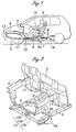
- FIG. 1 is a schematic side view of a vehicle body structure embodying the present invention.
- the main frame 1 of the vehicle body comprises a floor member 2 defining a floor of a passenger compartment, a dashboard panel 3 extending upright from the front end of the floor member 2, and a pair of front side beams 4 extending from the dashboard panel 3 to the front end of the vehicle body on either side thereof.
- the dashboard panel 3 defines a rear end of an engine room and a front end of the passenger compartment.
- a sub frame 5 is provided in a lower part of the engine room, and a front end of the sub frame 5 is joined to the front end of the front side beams 4 by a front member 13 including a pair of lateral members 13a and 13b and a vertical member 13c while the rear end of the sub frame 5 is integrally connected to a pair of connecting members 6 which extend rearward under the floor member 2 although only one of them is shown in Figure 1.
- the sub frame 5 forms a crash load transmitting member jointly with the connecting members 6 as described hereinafter.
- each of the connecting members 6 is integrally provided with an upright member 6a which is passed into the passenger compartment through a hole formed in the floor member 2.
- the upper end of the upright member 6a is attached to a seat base 7 supporting the lower surface of a seat 8.
- the two connecting members 6 having an identical structures are disposed on either side of the vehicle body, but only one of them is described in the following for the convenience of description.
- the seat 8 is slidably supported by the seat base 7 via guide rails (not shown in the drawings) fixedly attached to the seat base 7 so that the seat 8 can move in the fore-and-aft direction relative to the seat base 7 and the floor member 2 for adjustment.
- the seat 8 is incorporated with a seat belt 10 having three ends which are all anchored to the seat 8 so as to effectively restrain a vehicle occupant 9 in the seat 8 without regard to the fore-and-aft position of the seat 8.
- the seat belt may also consist of a more conventional seat belt having one or two of the anchor points which are attached to the vehicle body.
- a pair of floor frame members 11 are fixedly attached to the lower surface of a comer defined between the floor member 2 and the front dashboard panel 3 on either side of the vehicle body to reinforce the part connecting the front side beams 4 with the front dashboard panel 3.
- a holder 12 made of stamp formed sheet metal having a rectangular cross section in the shape of letter C is fixedly attached to the lower surface of each of the floor frame members 11 by using threaded bolts 15 as shown in Figure 3. The end of the sub frame 5 facing the passenger compartment is retained by the holders 12 which are fixedly attached to the lower surfaces of the corresponding floor frame members 11.
- the sub frame 5 is integrally provided with a bracket 5a on each side for supporting a wheel suspension system (not shown in the drawing), in particular a base end of a major lower arm thereof.
- a cross member 5c extends laterally across the sub frame 5.
- the sub frame 5 also supports an engine via brackets 5b of which only one of them is shown in Figure 3.
- the sub frame 5 of this embodiment is used not only for supporting the engine and wheel suspension systems but also for absorbing the impact of a vehicle crash as described hereinafter.
- the shape of the inner recess defined by the holder 12 closely conforms to the outer circumferential surface of the corresponding part of the sub frame 5 so that the sub frame 5 can be frictionally retained by the holder 12 by suitably selecting the fastening force of the threaded bolts 15. It is preferable to interpose a lubricating plastic member between the inner surface of the holder 12 and the part of the sub frame 5 frictionally retained by the holder 12, and fasten the threaded bolts 15 so that the sub frame 5 may be retained by a prescribed retaining force. This retaining force is selected to be smaller than the load that will cause a buckling deformation of the sub frame 5 when it is applied to the front end of the sub frame 5.
- the sub frame 5 is adapted to move rearward with respect to the vehicle body when subjected to a load resulting from a frontal vehicle crash, instead of undergoing a buckling deformation, until the sub frame 5 or the connecting member 6 collides with a member which is capable of withstanding the reaction from the buckling deformation of the sub frame 5.
- a stopper 14 is fixedly attached to the floor member 2 at a certain distance from the rear end of the connecting member 6 so that the connecting member 6 collides with the stopper 14 when the connecting member 6 has moved rearward by a prescribed distance in an intermediate phase of a frontal vehicle crash.
- the collision of the connecting member 6 with the stopper 14 creates a reverse deceleration to the connecting member 6 and the seat 8 attached to it.
- the front ends of the front side beams 4 and sub frame 5 are both subjected to an impulsive load. Because the rear end of the sub frame 5 is only frictionally engaged by the holders 12 as mentioned earlier, input of a large crash load causes the sub frame 5 to slide rearward relative to the holders 12 while the front side beams 4 undergo a compressive or buckling deformation.
- the seat 8 which is fixedly attached to the sub frame 5 via the connecting member 6 decelerates more sharply and strongly (interval a in Figure 14) than the main frame 1 which is directly connected to the front side beams 4. At this time, in appearance, the seat 8 moves rearward relative to the floor member 2 which continues to move forward owing to the compressive deformation of the front side beams 4.
- the occupant tends to move forward under the inertia force during this phase, but the restraint of the seat belt 10 prevents the forward movement of the vehicle occupant 9.
- the sub frame 5 having a front end which has been relatively intact in spite of the relatively high deceleration acting thereon eventually collides with the stopper 14 via the rear end of the connecting member 6.
- This causes a force opposing the crash load acting on the sub frame 5 to be transmitted to the seat 8 via the connecting member 6.
- the forward acceleration resulting from this collision cancels the forward inertia force acting on the vehicle occupant 9 (first half of interval b in Figure 14).
- the stopper 14 is firm enough to withstand the impulsive load which will cause a compressive or collapsing deformation of the sub frame 5.
- the crash load at the time of a frontal vehicle crash is transmitted to the sub frame 5 in the early phase of the crash, but not so much to the floor member 2 which is part of the vehicle body. Therefore, the sub frame 5 simply moves rearward, instead of undergoing a buckling deformation. Only after the connecting member 6 has collided with the stopper 14 and subjected to the resulting forward acceleration, the seat 8 is allowed to decelerate in a single body with the vehicle body main frame 1.
- the mode of guiding the rearward movement of the crash load transmitting member (sub frame 5 and connecting member 6 in the foregoing embodiment) relative to the main frame 1 is not limited by the above illustrated embodiment, but may consist of any other structure which joins the crash load transmitting member to the main frame so as to allow a relative displacement between them to take place at a crash load which is lower than that would cause a buckling or compressive deformation of the crash load transmitting member.
- the guide member consists of a part of the sub frame 5 having a guide slot 21 formed therein.
- the guide slot 21 extends in the fore-and-aft direction.
- the sub frame 5 is mounted on the under surface of the floor frame member 11 by a threaded bolt 22 passed through the slot 21.
- a collar 23 is fitted onto the threaded bolt 22.
- the inner surface of the slot 21 and/or the upper surface of the sub frame 5 which abuts the lower surface of the floor frame member 11 may be lined with a suitable friction material to control the friction with the corresponding parts.
- the sub frame 5 is retained by the floor frame member 11 with a retaining force which is less than that required for supporting the buckling or compressive deformation of the sub frame 5, and the rearward movement of the sub frame 5 is guided by the cooperation between the slot 21 and the threaded bolt 22.
- This embodiment provides similar advantages as those provided by the previous embodiment, and produces a deceleration time history at the time of a vehicle crash similar to that of the previous embodiment.
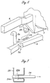
- a third embodiment is described in the following with reference to Figures 6 and 7, and the parts corresponding to those of the previous embodiments are denoted with like numerals.
- a pin 24 integrally extends from the sub frame 5 in the forward direction.
- a hollow holder 25 is fixedly attached to the under side of the floor frame member 11. The free end of the pin 24 is provided with an enlarged head 24a.
- the holder 25 is provided with a funnel shaped insertion hole 25a which is adapted to resiliently expand when the head 24a is pushed thereinto and retain the head 24a therein with a certain retaining force which opposes the effort to pull the head 24a rearward as indicated by the arrow in the drawing.
- This retaining force is again smaller than the force that will be required to cause a buckling or compressive deformation of the sub frame 5.
- This embodiment also provides similar advantages, and a similar deceleration waveform at ihe time of a vehicle crash.
- Figures 8 and 9 show a fourth embodiment of the present invention.
- the parts corresponding to those of the previous embodiments are denoted with like numerals.
- This embodiment is similar to the first embodiment, but the connecting member 6 extends only to a middle part of the passenger compartment.
- the holder 26 frictionally engages the sub frame 5 in a similar manner as the first embodiment, but additionally serves as a stopper in cooperation with a bulge member 28 attached to a part of the sub frame 5 which is located ahead of the holder 26 by a prescribed distance.
- the bulge member may consist of any unitary or separate enlarged part of the sub frame 5.
- the holder 26 is provided with a front end 26a which is adapted to undergo a compressive or buckling deformation as the sub frame 5 moves rearward under an impulsive load resulting from a vehicle crash before holding the sub frame 5 stationary with respect to the main frame 1.
- the front end 26a of the holder 26a serves as a cushioning member which prevents a sharp change in the deceleration of the sub frame 5.
- the frictional retaining force and the reaction force resulting from the compressive or buckling deformation of the front end 26a of the holder 26 are each lower than ihe force that is required to cause a buckling or compressive deformation of the sub frame 5.
- both the front side beams 4 and sub frame 5 are subjected to an impulsive load, and start deformation. Because the holder 26 frictionally engages the sub frame 5 in a similar manner as the first embodiment the sub frame 5 remains relatively intact as opposed to the front side beams 4 which undergoes a buckling or compressive deformation to a more significant extent.
- the seat 8 which is fixedly attached to the sub frame 5 via the connecting member 6 decelerates more sharply and strongly than the vehicle body main frame 1 (interval a of Figure 14).
- the seat 8, in appearance moves rearward relative to the floor member 2 which continues to move forward as the front side beams 4 undergo a buckiing or comp.ressive deformation.
- the vehicle occupant 9 tends to move forward under the inertia force, but the restraining force of the seat belt 10 acting on the vehicle occupant 9 increases and prevents the occupant 9 from moving forward.
- the bulge member 28 which is fixedly attached to the sub frame 5 collides with the holder 26, the foriner being subjected to a high deceleration with its front end withstanding the load.
- the inertia force of the main frame 1 is eventually transinitted to the bulge member 28, and the resulting impulsive load causes a buckling deformation of the front end 26a of the holder 26.
- the relative movement between the main frame 1 (including the front side beams 4 and floor member 2) and the connecting member 6 (including the seat 8) continues until the holder 26 has completed its buckling deformation.
- the stopper (holder 26 and bulge member 28) for the crash load transmitting member (the sub frame 5 and connecting member 6) is provided in a part of the vehicle body which can readily provide an adequate rigidity such as the engine room (of a front engine vehicle), the restriction on the design of the passenger compartment can be minimized, and the freedom in the design of the vehicle body can be increased with the added advantage of optimizing the distribution of the vehicle body rigidity.
- the arrangement for the stopper can be made both compact and light-weight.
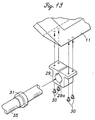
- FIG. 11 shows a fifth embodiment of the present invention, and the parts corresponding to those of the previous embodiments are denoted with like numerals.
- a pair of lower front side beams 35 are provided under the engine room on either side of the vehicle body, instead of a sub frame.
- Each lower front side beam 35 is passed through an inner bore 29a defined by a holder 29 which is made of a relatively solid member and firmly attached to the floor frame member 11 by threaded bolts 30.
- a collar 31 is fitted onto the lower front side beam 35 at a point which is located ahead of the holder 29 by a prescribed distance.
- the collar 31 includes a relatively solid base end 31a which is firmly secured to the lower front side beam 35, and an extension 31b which extends from the base end 31a toward the holder 29, and is adapted to undergo a compressive or buckling deformation when it is pushed onto the holder 29.
- the lower front side beam 35 initially moves rearward along with the connecting member 6 and the seat 8 which are integral with the lower front side beam 35 in the same way as in the previous embodiment while the upper front side beams 4 undergo a compressive or buckling deformation.
- the extension 31b abuts the holder 29, and collapses by undergoing a compressive or buckling deformation as illustrated in Figure 12.
- the base end 31a abuts the holder 29, and this causes the lower front side beams 35 to move jointly with the main frame 1.
- the action and effect of this embodiment are similar to those of the previous embodiments, and a similar deceleration time history can be achieved at the time of a vehicle crash as the previous embodiments.
- Figure 13 shows a sixth embodiment of the present invention which is similar to the previous embodiment, but lacks the extension 31b extending from the base end 31a of the collar 31. Therefore, as the lower front side beams 35 move rearward and cause a sharp rise in the deceleration of the seat 8 which is attached to the front side beams 35 via a connecting member 6, it simply abuts the holder 29, and causes the lower front side beams 35 to move in a single body with the vehicle body main frame 1.
- the action and effect of this embodiment are similar to those of the previous embodiments, and a similar deceleration waveform can be achieved at the time of a vehicle crash as the previous embodiments.
Claims (11)
- Kraftfahrzeugkarosseriestruktur, welche umfasst:wobei der vorgeschriebene Grenzwert kleiner ist als ein Wert, welcher eine kollabierende Verformung des Hilfsrahmens (5) verursachen wird.einen Fahrzeugkarosserie-Hauptrahmen (1) mit einem einen Boden einer Passagierkabine definierenden Bodenelement (2), einer von einem vorderen Ende des Bodenelements aufrecht verlaufenden Armaturenbrettplatte (3) und einem Paar zwischen einem vorderen Ende der Fahrzeugkarosserie und der Armaturenbrettplatte verlaufender vorderer Seitenholme (4);ein Kollisionskraftübertragungselement (5, 6, 35), welches von einem vorderen Ende der Fahrzeugkarosserie zu einem dem Bodenelement (2) benachbarten Abschnitt verläuft;einen Fahrzeugsitz (8), welcher mit dem Kollisionskraftübertragungselement (5, 6, 35) verbunden ist;ein Führungselement (12; 21, 22; 24, 25; 26; 29), welches an dem Hauptrahmen (1) einem unteren Ende der Armaturenbrettplatte 3 benachbart angeordnet und dazu eingerichtet ist, das Kollisionskraftübertragungselement (5, 6, 35) normalerweise durch Reibungshaltekräfte, die zwischen dem Führungselement (12; 21, 22; 24, 25; 26; 29) und dem Kollisionskraftübertragungselement (5, 6, 35) wirken, starr zu befestigen, jedoch dem Kollisionskraftübertragungselement (5, 6, 35) zu erlauben, sich zum Heck der Fahrzeugkarosserie hin zu bewegen, wenn das Kollisionskraftübertragungselement (5, 6, 35) einer nach hinten gerichteten, einen vorgeschriebenen Grenzwert überschreitenden Kraft ausgesetzt ist;wobei das Kollisionskraftübertragungselement (5, 6, 35) einen Hilfsrahmen (5) umfasst, welcher von dem vorderen Ende der Fahrzeugkarosserie zu dem Führungselement (12; 21, 22; 24, 25; 26; 29) verläuft, sowie ein Verbindungsteil (6) umfasst, welches von dem Hilfsrahmen (5) zu dem Fahrzeugsitz (8) verläuft, wobei der Hilfsrahmen (5) für eine kollabierende Verformung unter einer Kollisionskraft eingerichtet ist;einen Stopper (14, 26, 29), welcher starr an dem Hauptrahmen (1) angebracht und dafür eingerichtet ist, bei einer rückwärts gerichteten Bewegung des Kollisionskraftübertragungselements (5, 6, 35) um eine vorgeschriebene Distanz mit einem Abschnitt des Kollisionskraftübertragungselements (5, 6, 35) zusammenzustoßen;
- Kraftfahrzeugkarosseriestruktur nach Anspruch 1, wobei der Stopper (26, 29) einem unteren Ende der Armaturenbrettplatte benachbart gelegen ist.
- Kraftfahrzeugkarosseriestruktur nach Anspruch 1, wobei das Führungselement einem unteren Ende der Armaturenbrettplatte benachbart gelegen ist und wobei in einem Abschnitt des Kollisionskraftübertragungselements, welcher um die vorgeschriebene Distanz vor dem Führungselement liegt, ein vergrößerter Abschnitt (28, 31) bereitgestellt ist, so dass das Führungselement als der Stopper dienen kann, welcher mit dem vergrößerten Abschnitt zusammenstoßen kann, wenn sich das Kollisionskraftübertragungselement um die vorgeschriebene Distanz nach hinten bewegt.
- Kraftfahrzeugkarosseriestruktur nach Anspruch 3, wobei ein Dämpfungselement (26a, 31 b) zwischen dem Führungselement und dem vergrößerten Abschnitt des Kollisionskraftübertragungselements bereitgestellt ist.
- Kraftfahrzeugkarosseriestruktur nach Anspruch 4, wobei das Dämpfungselement ein plastisch kollabierbares Ansatzstück (31 b) des vergrößerten Abschnitts umfasst.
- Kraftfahrzeugkarosseriestruktur nach Anspruch 4, wobei das Dämpfungselement ein plastisch kollabierbares Ansatzstück (26a) des Führungselements umfasst.
- Kraftfahrzeugkarosseriestruktur nach Anspruch 1, wobei der Stopper (14) dem hinteren Ende des Bodenelements benachbart bereitgestellt ist.
- Kraftfahrzeugkarosseriestruktur nach Anspruch 1, wobei das Kollisionskraftübertragungselement einen Hilfsrahmen (5) umfasst, welcher dafür eingerichtet ist, einen Motor oder/und ein Radaufhängungssystem zu tragen.
- Kraftfahrzeugkarosseriestruktur nach Anspruch 1, wobei das Führungselement eine kanalförmige Halterung (12, 26, 29) umfasst, weiche einen Abschnitt des Kollisionskraftübertragungselements umgibt, so dass eine vorgeschriebene Reibungshaltekraft erzielt wird.
- Kraftfahrzeugkarosseriestruktur nach Anspruch 1, wobei das Führungselement einen Stab (22) umfasst, welcher durch einen Längsschlitz (21) hindurchgeführt ist, der in einem von dem Hauptrahmen und dem Kollisionskraftübertragungselement ausgebildet ist und an dem anderen von dem Hauptrahmen und dem Kollisionskraftübertragungselement befestigt ist, so dass eine vorgeschriebene Reibungshaltekraft erzielt wird.
- Kraftfahrzeugkarosseriestruktur nach Anspruch 1, wobei das Führungselement einen Stab (24) umfasst, welcher sich in der Längsrichtung von einem von dem Hauptrahmen und dem Kollisionskraftübertragungselement aus erstreckt, und ein Loch (25a) umfasst, welches in dem anderen von dem Hauptrahmen und dem Kollisionskraftübertragungselement ausgebildet ist, um den Stab aufzunehmen und mit einer vorgeschriebenen Haltekraft zu halten.
Applications Claiming Priority (4)
| Application Number | Priority Date | Filing Date | Title |
|---|---|---|---|
| JP34600599 | 1999-12-06 | ||
| JP34599999 | 1999-12-06 | ||
| JP34600599 | 1999-12-06 | ||
| JP34599999 | 1999-12-06 |
Publications (3)
| Publication Number | Publication Date |
|---|---|
| EP1106479A2 EP1106479A2 (de) | 2001-06-13 |
| EP1106479A3 EP1106479A3 (de) | 2002-05-08 |
| EP1106479B1 true EP1106479B1 (de) | 2004-04-14 |
Family
ID=26578159
Family Applications (1)
| Application Number | Title | Priority Date | Filing Date |
|---|---|---|---|
| EP00126230A Expired - Fee Related EP1106479B1 (de) | 1999-12-06 | 2000-11-30 | Fahrzeugkarrosseriestruktur für verbesserte Unfallsicherheit |
Country Status (5)
| Country | Link |
|---|---|
| US (1) | US6398292B2 (de) |
| EP (1) | EP1106479B1 (de) |
| BR (1) | BR0005725A (de) |
| CA (1) | CA2327535A1 (de) |
| DE (1) | DE60009840T2 (de) |
Families Citing this family (37)
| Publication number | Priority date | Publication date | Assignee | Title |
|---|---|---|---|---|
| SE514294C2 (sv) * | 1998-09-30 | 2001-02-05 | Volvo Lastvagnar Ab | Anordning som möjliggör förskjutning av förarutrymmet hos ett fordon |
| US6402218B1 (en) * | 1999-07-23 | 2002-06-11 | Honda Giken Kogyo Kabushiki Kaisha | Seat belt pretensioner device powered by vehicle body deformation |
| JP4511768B2 (ja) | 2001-06-12 | 2010-07-28 | 本田技研工業株式会社 | 乗員保護装置 |
| JP4448626B2 (ja) * | 2001-07-18 | 2010-04-14 | 本田技研工業株式会社 | 乗員保護装置 |
| JP4621384B2 (ja) * | 2001-07-18 | 2011-01-26 | 本田技研工業株式会社 | 乗員保護装置 |
| US6655729B2 (en) * | 2001-09-13 | 2003-12-02 | Intier Automotive Inc. | Bridge assembly |
| DE10202984A1 (de) * | 2002-01-26 | 2003-08-07 | Porsche Ag | Aufbaustruktur eines Kraftfahrzeugs |
| DE10202957A1 (de) * | 2002-01-26 | 2003-08-07 | Porsche Ag | Aufbau für Kraftfahrzeuge |
| DE10208512B4 (de) * | 2002-02-27 | 2008-11-13 | Daimler Ag | Tragstruktur eines Kraftfahrzeugs |
| JP4010169B2 (ja) * | 2002-04-09 | 2007-11-21 | 三菱自動車工業株式会社 | 車体構造 |
| JP4144340B2 (ja) * | 2002-12-05 | 2008-09-03 | 日産自動車株式会社 | 車体前部構造 |
| JP3786093B2 (ja) * | 2003-02-07 | 2006-06-14 | 日産自動車株式会社 | 車体前部構造 |
| FR2851523B1 (fr) * | 2003-02-26 | 2005-03-25 | Peugeot Citroen Automobiles Sa | Siege de vehicule automobile retractable en cas de choc ou de retournement |
| US6886884B2 (en) * | 2003-07-21 | 2005-05-03 | Daimlerchrysler Corporation | Reducing localized deflection in the body of a body-on-frame vehicle |
| US7413240B2 (en) * | 2003-09-03 | 2008-08-19 | Specialty Vehicle Acquisition Corp. | Structural system for a convertible automotive vehicle |
| US20050046235A1 (en) | 2003-09-03 | 2005-03-03 | Robertson James E. | Structural reinforcement system for an automotive vehicle |
| US7246845B2 (en) | 2003-09-03 | 2007-07-24 | Asc Incorporated | Structural seat system for an automotive vehicle |
| US7481486B2 (en) * | 2003-09-03 | 2009-01-27 | Specialty Vehicle Acquisition Corp. | Structural seat system for an automotive vehicle |
| US7413242B2 (en) * | 2003-09-03 | 2008-08-19 | Specialty Vehicle Acquisition Corp. | Structural seat system for an automotive vehicle |
| JP4325351B2 (ja) * | 2003-10-08 | 2009-09-02 | 三菱自動車工業株式会社 | 車両のシャシ取付構造 |
| US8075048B2 (en) * | 2004-08-31 | 2011-12-13 | Toray Industries, Inc. | Bonnet for automobile having automobiles that protects the heads of pedestrians |
| US7281755B2 (en) * | 2004-12-07 | 2007-10-16 | Nissan Technical Center North America, Inc. | Vehicle support structure with floor impact movement restriction device |
| US7275785B2 (en) * | 2005-06-08 | 2007-10-02 | Ford Global Technologies, Llc | Rear subframe attachment mount for hydroformed frame |
| JP4680784B2 (ja) * | 2006-01-17 | 2011-05-11 | 本田技研工業株式会社 | 自動車の前部車体構造 |
| DE102006026120A1 (de) * | 2006-06-03 | 2007-12-06 | GM Global Technology Operations, Inc., Detroit | Karosserie für ein Kraftfahrzeug |
| KR100820714B1 (ko) * | 2006-12-14 | 2008-04-11 | 현대자동차주식회사 | 자동차의 리어 서스펜션 크로스 멤버 장착 구조 |
| JP5201864B2 (ja) * | 2007-03-30 | 2013-06-05 | 三菱自動車工業株式会社 | 車体構造 |
| FR2914619B1 (fr) * | 2007-04-06 | 2009-05-22 | Renault Sas | Vehicule automobile qui comporte deux longerons et des moyens de fixation du moteur auxdits longerons |
| US7770927B2 (en) * | 2008-04-18 | 2010-08-10 | Gm Global Technology Operations, Inc. | Energy absorbing system for a vehicle |
| DE102011103090A1 (de) * | 2011-05-25 | 2012-11-29 | Thyssenkrupp Steel Europe Ag | Fahrzeugkarosserie und deren Verwendung |
| JP5953887B2 (ja) * | 2012-04-02 | 2016-07-20 | マツダ株式会社 | 車両の車体前部構造 |
| JP6148915B2 (ja) * | 2012-09-26 | 2017-06-14 | 株式会社Subaru | 車両 |
| US9376142B2 (en) * | 2014-05-22 | 2016-06-28 | Nissan North America, Inc. | Vehicle support structure |
| US9643651B2 (en) | 2015-08-28 | 2017-05-09 | Honda Motor Co., Ltd. | Casting, hollow interconnecting member for connecting vehicular frame members, and vehicular frame assembly including hollow interconnecting member |
| US10239559B2 (en) | 2016-03-14 | 2019-03-26 | Honda Motor Co., Ltd. | Vehicle frames and methods of assembling the same |
| US10081245B2 (en) * | 2016-06-24 | 2018-09-25 | GM Global Technology Operations LLC | Cradle to body joint release mechanism |
| FR3080364B1 (fr) * | 2018-04-19 | 2020-05-08 | Zodiac Seats France | Systeme de deverrouillage par inertie d'un dossier de siege |
Family Cites Families (12)
| Publication number | Priority date | Publication date | Assignee | Title |
|---|---|---|---|---|
| US3001815A (en) * | 1958-02-25 | 1961-09-26 | Robert C Weber | Bumper actuated vehicle safety seat |
| US2959446A (en) * | 1958-04-24 | 1960-11-08 | Thompson William Francis | Automobile crash absorbing construction |
| FR2147012A1 (de) * | 1971-07-29 | 1973-03-09 | Angelucci Marc | |
| DE3424928A1 (de) * | 1984-07-06 | 1986-01-16 | Walter 8720 Schweinfurt Lindwurm | Schleudersitz - sicherheitsanlage fuer kraftfahrzeuge |
| DE4323543C1 (de) * | 1993-03-31 | 1994-10-06 | Mueller Franz Dipl Ing Fh | Sicherheitseinrichtung für Fahrzeuge |
| JPH07101354A (ja) | 1993-10-05 | 1995-04-18 | Isuzu Motors Ltd | 車両用サイドメンバ |
| WO1997012799A1 (fr) * | 1995-10-02 | 1997-04-10 | Gailland, Jean-Claude | Vehicule automobile comportant un chassis secondaire pouvant coulisser vers l'arriere sur un chassis principal suite a un choc avant |
| DE19711392C1 (de) * | 1997-03-19 | 1998-10-29 | Giok Djien Dr Ing Go | Lenksäule und Sicherheitsgurte eines Fahrzeuges mit Schutzvorrichtung |
| US5947543A (en) * | 1997-04-03 | 1999-09-07 | Hubbard; Leo James | Vehicle safety system |
| JP3459776B2 (ja) * | 1998-08-20 | 2003-10-27 | 本田技研工業株式会社 | 乗員保護装置 |
| JP2000062557A (ja) * | 1998-08-20 | 2000-02-29 | Honda Motor Co Ltd | 乗員保護装置 |
| JP2001039249A (ja) * | 1999-07-30 | 2001-02-13 | Honda Motor Co Ltd | 自動車の車体構造 |
-
2000
- 2000-11-30 DE DE60009840T patent/DE60009840T2/de not_active Expired - Fee Related
- 2000-11-30 EP EP00126230A patent/EP1106479B1/de not_active Expired - Fee Related
- 2000-12-04 CA CA002327535A patent/CA2327535A1/en not_active Abandoned
- 2000-12-05 BR BR0005725-8A patent/BR0005725A/pt active Search and Examination
- 2000-12-06 US US09/729,973 patent/US6398292B2/en not_active Expired - Fee Related
Also Published As
| Publication number | Publication date |
|---|---|
| DE60009840D1 (de) | 2004-05-19 |
| CA2327535A1 (en) | 2001-06-06 |
| US20010002761A1 (en) | 2001-06-07 |
| EP1106479A3 (de) | 2002-05-08 |
| DE60009840T2 (de) | 2005-04-21 |
| EP1106479A2 (de) | 2001-06-13 |
| BR0005725A (pt) | 2001-07-17 |
| US6398292B2 (en) | 2002-06-04 |
Similar Documents
| Publication | Publication Date | Title |
|---|---|---|
| EP1106479B1 (de) | Fahrzeugkarrosseriestruktur für verbesserte Unfallsicherheit | |
| EP1266804B1 (de) | Seitenaufprall-Personenschutzsystem im Kraftfahrzeug | |
| US6186574B1 (en) | Vehicle occupant protection system | |
| US6863308B2 (en) | Automotive vehicle occupant protection system | |
| US6193296B1 (en) | Vehicle occupant protection system | |
| JP2856550B2 (ja) | 自動車内の安全装置 | |
| US6312038B1 (en) | Automotive vehicle body structure | |
| US6843504B2 (en) | Automotive vehicle occupant protection system | |
| US4232895A (en) | Impact absorbing device for protecting vehicle's occupant from impact caused by collision | |
| EP1078812B1 (de) | Fahrzeuginsassenschutzsystem | |
| EP1266809B1 (de) | Kraftfahrzeug Insassenschutzsystem | |
| EP1106480B1 (de) | Einrichtung zum Schutz der Insassen | |
| US6578894B2 (en) | Automotive vehicle occupant protection system | |
| CN110884398B (zh) | 固定座椅缓冲器 | |
| EP1106482B1 (de) | Einrichtung zum Schutz der Insassen | |
| JP4048004B2 (ja) | 自動車の車体構造 | |
| JP2001163250A (ja) | 自動車の車体構造 | |
| JP2002120680A (ja) | 乗員保護装置 | |
| JP2001225765A (ja) | 自動車の車体構造 | |
| JP2001225764A (ja) | 自動車の車体構造 | |
| JP2001163175A (ja) | 乗員保護装置 | |
| JPS6050611B2 (ja) | 衝突時における車両乗員の衝撃吸収装置 | |
| JP2003306109A (ja) | 乗員保護装置 | |
| JP2002205616A (ja) | 乗員保護装置 |
Legal Events
| Date | Code | Title | Description |
|---|---|---|---|
| PUAI | Public reference made under article 153(3) epc to a published international application that has entered the european phase |
Free format text: ORIGINAL CODE: 0009012 |
|
| AK | Designated contracting states |
Kind code of ref document: A2 Designated state(s): AT BE CH CY DE DK ES FI FR GB GR IE IT LI LU MC NL PT SE TR |
|
| AX | Request for extension of the european patent |
Free format text: AL;LT;LV;MK;RO;SI |
|
| PUAL | Search report despatched |
Free format text: ORIGINAL CODE: 0009013 |
|
| AK | Designated contracting states |
Kind code of ref document: A3 Designated state(s): AT BE CH CY DE DK ES FI FR GB GR IE IT LI LU MC NL PT SE TR |
|
| AX | Request for extension of the european patent |
Free format text: AL;LT;LV;MK;RO;SI |
|
| 17P | Request for examination filed |
Effective date: 20020704 |
|
| AKX | Designation fees paid |
Designated state(s): DE FR GB |
|
| 17Q | First examination report despatched |
Effective date: 20030129 |
|
| GRAP | Despatch of communication of intention to grant a patent |
Free format text: ORIGINAL CODE: EPIDOSNIGR1 |
|
| RIN1 | Information on inventor provided before grant (corrected) |
Inventor name: YOSHIDA, KAZUYO Inventor name: MOTOZAWA, YASUKI Inventor name: KAMEI, TAKAHIRO Inventor name: TSURUTA, MAKOTO |
|
| GRAS | Grant fee paid |
Free format text: ORIGINAL CODE: EPIDOSNIGR3 |
|
| GRAA | (expected) grant |
Free format text: ORIGINAL CODE: 0009210 |
|
| AK | Designated contracting states |
Kind code of ref document: B1 Designated state(s): DE FR GB |
|
| REG | Reference to a national code |
Ref country code: GB Ref legal event code: FG4D |
|
| REF | Corresponds to: |
Ref document number: 60009840 Country of ref document: DE Date of ref document: 20040519 Kind code of ref document: P |
|
| REG | Reference to a national code |
Ref country code: IE Ref legal event code: FG4D |
|
| PGFP | Annual fee paid to national office [announced via postgrant information from national office to epo] |
Ref country code: DE Payment date: 20040930 Year of fee payment: 5 |
|
| PGFP | Annual fee paid to national office [announced via postgrant information from national office to epo] |
Ref country code: GB Payment date: 20041122 Year of fee payment: 5 |
|
| PGFP | Annual fee paid to national office [announced via postgrant information from national office to epo] |
Ref country code: FR Payment date: 20041126 Year of fee payment: 5 |
|
| ET | Fr: translation filed | ||
| PLBE | No opposition filed within time limit |
Free format text: ORIGINAL CODE: 0009261 |
|
| STAA | Information on the status of an ep patent application or granted ep patent |
Free format text: STATUS: NO OPPOSITION FILED WITHIN TIME LIMIT |
|
| 26N | No opposition filed |
Effective date: 20050117 |
|
| PG25 | Lapsed in a contracting state [announced via postgrant information from national office to epo] |
Ref country code: GB Free format text: LAPSE BECAUSE OF NON-PAYMENT OF DUE FEES Effective date: 20051130 |
|
| PG25 | Lapsed in a contracting state [announced via postgrant information from national office to epo] |
Ref country code: DE Free format text: LAPSE BECAUSE OF NON-PAYMENT OF DUE FEES Effective date: 20060601 |
|
| GBPC | Gb: european patent ceased through non-payment of renewal fee |
Effective date: 20051130 |
|
| PG25 | Lapsed in a contracting state [announced via postgrant information from national office to epo] |
Ref country code: FR Free format text: LAPSE BECAUSE OF NON-PAYMENT OF DUE FEES Effective date: 20060731 |
|
| REG | Reference to a national code |
Ref country code: FR Ref legal event code: ST Effective date: 20060731 |