EP1105696B1 - Verfahren und vorrichtung zum bestimmen einer route von einem ausgangsort zu einem zielort - Google Patents
Verfahren und vorrichtung zum bestimmen einer route von einem ausgangsort zu einem zielort Download PDFInfo
- Publication number
- EP1105696B1 EP1105696B1 EP00945618A EP00945618A EP1105696B1 EP 1105696 B1 EP1105696 B1 EP 1105696B1 EP 00945618 A EP00945618 A EP 00945618A EP 00945618 A EP00945618 A EP 00945618A EP 1105696 B1 EP1105696 B1 EP 1105696B1
- Authority
- EP
- European Patent Office
- Prior art keywords
- route
- edge
- edges
- destination
- list
- Prior art date
- Legal status (The legal status is an assumption and is not a legal conclusion. Google has not performed a legal analysis and makes no representation as to the accuracy of the status listed.)
- Expired - Lifetime
Links
Images


Classifications
-
- G—PHYSICS
- G01—MEASURING; TESTING
- G01C—MEASURING DISTANCES, LEVELS OR BEARINGS; SURVEYING; NAVIGATION; GYROSCOPIC INSTRUMENTS; PHOTOGRAMMETRY OR VIDEOGRAMMETRY
- G01C21/00—Navigation; Navigational instruments not provided for in groups G01C1/00 - G01C19/00
- G01C21/26—Navigation; Navigational instruments not provided for in groups G01C1/00 - G01C19/00 specially adapted for navigation in a road network
- G01C21/34—Route searching; Route guidance
- G01C21/3453—Special cost functions, i.e. other than distance or default speed limit of road segments
- G01C21/3461—Preferred or disfavoured areas, e.g. dangerous zones, toll or emission zones, intersections, manoeuvre types, segments such as motorways, toll roads, ferries
-
- G—PHYSICS
- G01—MEASURING; TESTING
- G01C—MEASURING DISTANCES, LEVELS OR BEARINGS; SURVEYING; NAVIGATION; GYROSCOPIC INSTRUMENTS; PHOTOGRAMMETRY OR VIDEOGRAMMETRY
- G01C21/00—Navigation; Navigational instruments not provided for in groups G01C1/00 - G01C19/00
- G01C21/26—Navigation; Navigational instruments not provided for in groups G01C1/00 - G01C19/00 specially adapted for navigation in a road network
- G01C21/34—Route searching; Route guidance
- G01C21/3446—Details of route searching algorithms, e.g. Dijkstra, A*, arc-flags, using precalculated routes
-
- G—PHYSICS
- G06—COMPUTING; CALCULATING OR COUNTING
- G06Q—INFORMATION AND COMMUNICATION TECHNOLOGY [ICT] SPECIALLY ADAPTED FOR ADMINISTRATIVE, COMMERCIAL, FINANCIAL, MANAGERIAL OR SUPERVISORY PURPOSES; SYSTEMS OR METHODS SPECIALLY ADAPTED FOR ADMINISTRATIVE, COMMERCIAL, FINANCIAL, MANAGERIAL OR SUPERVISORY PURPOSES, NOT OTHERWISE PROVIDED FOR
- G06Q10/00—Administration; Management
- G06Q10/04—Forecasting or optimisation specially adapted for administrative or management purposes, e.g. linear programming or "cutting stock problem"
- G06Q10/047—Optimisation of routes or paths, e.g. travelling salesman problem
Definitions
- the invention relates to a method for determining a route from a starting point to a destination on the basis of a digital map which maps a real road network into edges with respective resistors and nodes, whereby edges optimized by means of a route search algorithm are stored in a route table for the route. wherein at least one intermediate destination is predetermined for the route, according to the preamble of claim 1.
- the invention further relates to a device for determining a route from a starting point to a destination on the basis of a digital map stored in a memory, which is a real road network in edges with respective resistances and nodes, according to the preamble of claim 11.
- corresponding navigation data for example based on maps, maps or road maps, are stored in the navigation system, for example on a CD-ROM.
- the navigation device uses, for example, GPS (Global Positioning System) to determine a current location and corresponding navigation instructions calculate which lead to a predetermined destination.
- the navigation data preferably contain data about roads and paths for motor vehicles.
- a driver of a motor vehicle can influence a course of a route to be calculated in various ways, namely by choosing different optimization criteria, such as “short route”, “fast route”, “shallow highway”, by manual or by traffic telematics Influence of road sections, which are then bypassed or favored in the route calculation, or by defining one or more intermediate destinations, which are then approached in order, and then finally lead to the final destination.
- optimization criteria such as "short route”, “fast route”, “shallow highway”
- traffic telematics Influence of road sections which are then bypassed or favored in the route calculation, or by defining one or more intermediate destinations, which are then approached in order, and then finally lead to the final destination.
- For the request of a driver "I would like to drive from Kassel over Hanover to Minden” offers the driver however only the latter possibility. He must define an interim destination in Hannover, which is for example the city center, after which two route calculations are initiated. A first route from Kassel to Hannover and a second route from Hannover to Minden
- Kirson AM "Route planning system with user selectable preferences", Motorola Technical Developments, US, Motorola Inc., Shaumburg, Illinois, Vol. 13, 01.07.1991 (1991-07-01), pages 58 to 59, XP 000 259 107 discloses an apparatus for determining a route from an origin to a destination based on a digital map stored in a memory which maps a real road network into edges having respective resistors and nodes.
- This device has means for input and definition of an intermediate destination defined in the form of a planar transition region of the digital map. The device is designed such that the route calculation is calculated in sections from the starting point to a point of the intermediate destination closest to the starting point and, in a second step, from a point of the intermediate destination closest to the destination to the destination.
- At least one intermediate destination is defined as a transitional area in the form of a group of edges, wherein in the determination of the route the resistance of the overall route from the starting point to all intermediate destinations to the destination is minimized.
- the route is optimized from the starting position via the transition area to the destination as a whole and not in sections.
- the driver does not have to worry about a concrete intermediate goal definition.
- the invention ensures that, after the calculation of the route at any time, the optimal route from any possible starting point or position of a vehicle to the destination via the transition area (s) is available. As a result, a corresponding distance to the destination, as well as a remaining travel time or an estimated time of arrival can always be specified.
- one or more ViaAreas are also taken into consideration in addition to conventional, predeterminable criteria, such as "short route”, “fast route” or the like, the ViaAreas being included in the calculated route in a user-defined order become.
- each intermediate target is defined as a transitional area in the form of a solid area of the digital map and corresponding edges of the corresponding transition area located in the area are allocated and stored in a transition area list, wherein a first edge optimization is from a destination edge corresponding to the destination carried out starting and the result is stored in a first route table, wherein further the number of predetermined
- the edges stored in the ground and destination initialized transition area list are updated with corresponding resistors from the first route table, further at the beginning of each
- the resistances of the edges stored in the respective current transition area list with resistances of the corresponding edges of the respective edge regions are entered into the respective basic initialized segment route table Section Routing Table will be updated, starting after the last section edge optimization starting with the last section route table to the first route table e from these a route list is put together so that the total resistance of the route from the starting point via one or more intermediate destinations to the destination is minimal
- the route list is composed in such a way that, starting with the section route table of the most recently executed section edge optimization, corresponding edges are successively entered in the route list until no successor is defined for an edge in the respective section route table and with this edge the next and further section route table to the first route table is proceeded in the same way, wherein the order in which the section route tables are processed in the transition area list is predetermined.
- a transition area description list and a transition area index table are stored in the transition area list, the transition area index table including assignment of transition areas to transition area description list and route tables, and the transition area description list including respective edges associated with a transition area with associated resistors.
- the destination with zero resistance is entered as the first entry in the transition area description list.
- the transition region is selected as a rectangle, polygon, ellipse or circle around a prominent point, in particular a city, agglomeration or motorway exit.
- transition areas can deliberately remain spatially blurred, since the driver only wants to achieve an influence on the overall route.
- a dynamic route influencing by a telematics service provider is possible, for example, a traffic flow to steer.
- a navigation computer in the vehicle remains completely autonomous and can respond autonomously and quickly to a deviation of the driver from the route.
- the area intermediate point is defined as a transitional area in the form of a group of cottages and for determining the route, the minimization of the resistance of the entire route from the starting point over all intermediate destinations to the destination is provided.
- this comprises a navigation computer, a mass data memory which contains the digital map as an image of the real road network, a sensor device, a locating device, a route search device, an index memory, an interface, a loudspeaker, a display device and an input device.
- the method of the invention determines a route from a point of departure to a destination via at least one user-defined intermediate destination based on a digital map base containing edges with correspondingly assigned resistance that correspond to respective real roads in a real road network.
- This or these intermediate goals are not exact, but spatially blurred indicated as surface areas.
- the total resistance of all the edges belonging to the route is minimized, wherein also within the intermediate goals several edges are available for selection, so that within the intermediate destinations an edge selection by the method according to the invention is carried out such that a minimization of the total resistance of the route is achieved.
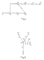
- the road network for mathematical processing by a route search algorithm is represented as a graph with edges k and node p, the edges representing corresponding roads and the nodes corresponding meshing points of the roads or the road network.
- edges k 1 , k 2 , k 3 , k 4 , k 5 , k 6 , k 7 and k 8 and eight nodes p 1 , p 2 , p 3 , p 4 , p 5 , P 6 , P 7 and p 8 provided. Since the traffic flow is directed in real traffic, an edge k must also be represented as a directed vector.
- the edges k are also resistances, Sogn.
- line resistances which is a measure of an effort to go from one node in the network to another.
- the edge length is used as a line resistance.
- a travel time on an edge may be considered as their respective road resistance.
- maneuvering resistors can be assigned to the nodes.
- the standard algorithm used for calculating the route is a method which is based on known best-path algorithms according to Ford or Moore from graph theory, these algorithms being adapted to the special requirements for use in self-sufficient vehicle navigation systems.
- Such best-path algorithms work backward iteratively for route computation and visit all edges in the graph and evaluate them for the best ways to the target edge.
- a resistively favorable path is searched for listed edges, which have been optimized in the previous iteration step.
- the method returns from each edge in the graph an optimal route to the target edge.
- Route table created. Such a table would look like the example of the graph shown in FIG. 1 as follows. Tab.
- the table shows the resistance up to the target edge and the trailing edge following in the target direction.
- Initialization value is the resistance to "infinite" (symbol ⁇ ) and the trailing edge is set to "undefined” (symbol -).
- a positive sign in the resistance and successor column stands for the consideration of the respective edge in its direction of the arrow, whereas a negative sign stands for the consideration of the respective edge opposite to the direction of the arrow.
- the target edge in the route table is initialized to zero resistance.
- a target edge should first serve the edge k 1 .
- the result for a destination initialization is the following appearance for the stored route table.
- Tab.2 Route table edge + resistance + Successor edge -Resistance -Nach discountedkante k 1 0 - 0 - k 2 ⁇ - ⁇ - k 3 ⁇ - ⁇ - k 4 ⁇ - ⁇ - k 5 ⁇ - ⁇ - k 6 ⁇ - ⁇ - k 7 ⁇ - ⁇ - k 8 ⁇ - ⁇ -
- the method now starts after the above initialization by considering all the edges listed in the list 1 as a fictitious actual position of the vehicle and all meshed with this "actual edge” edges, the sogn. Subjecting "Ankommer Edges" to an optimization test (O).
- O Ankommer Edges
- the result is the situation illustrated in FIG. 2, where O1a, O1b and O2c denote respective optimization tests.
- the edge k 1 is the actual edge, while the edges k 2 and k 3 are Ankommer edges.
- resistance denotes the resistance entered in the route table and "line resistance” a line resistance associated with the respective edge in the graph (see FIG.
- line resistance a line resistance associated with the respective edge in the graph
- optimization occurs when the condition is met, ie, the new resistance of the incoming edge is less than the old resistance.
- the resistance of the incoming edge is indicated in the route table by the new, smaller value replaced, as the successor edge, the actual edge is entered and added the optimized Ankommer edge in the list 2.
- lists 1 and 2 are swapped, i.
- the starting point for the next optimization are the edges optimized in the last step.
- the method terminates if List 1 is found empty, i. there were no optimized edges in the previous run.
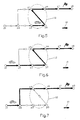
- Fig. 3 the network to be considered is shown, wherein arrow 10 denotes a route direction. It is assumed that all edges have the resistance value 10, except edge k 2 , which should have a resistance value of 15. The goal is the edge k 8 . From the current actual position (edge k 1 ), the optimal route to the destination k 8 should be determined. In the application of the previously described Bestwege algorithm according to Ford, Moore and the corresponding optimization rule with respect to the resistance, the route also shown in Fig. 3 results. The total resistance is 45.
- the example network is to be extended by an intermediate target 12, consisting of the edges k 4 , k 5 and k 6 , as shown in Fig. 4 to 6.
- the Route from the current actual position (edge k 1 ) via the intermediate destination 12 to the destination (edge k 8 ) is divided into two successively calculated partial routes.
- the calculation of the partial routes is in both cases again according to the method and optimization rules described above.
- the first partial route is determined by the current actual position (edge k 1 ) to the intermediate destination 12.
- the result is the first partial route with resistance 20 shown in FIG. 4.
- the second partial route is determined by the end of the first partial route at the intermediate destination 12 to the destination. It is registered in Fig. 5 and has the resistor 40.
- the total route shown in FIG. 6 results from the start (edge k 1 ) via the intermediate destination 12 to the destination (edge k 8 ).
- ViaArea predetermined transition areas
- the via areas are specified, for example, via normal, geographic coordinates to which a predetermined geometry such as a circle, a rectangle, a polygon or an ellipse is mapped.
- the user preferably also has the option of selecting a point from a map.
- the shape of the ViaAreas, such as ellipse, rectangle or circle, as well as the size is suitably selectable via a menu or a menu item or directly in the map changeable.
- the following boundary conditions are given.
- Corresponding air-line distances between starting location, destination location and ViaArea define a maximum and a minimum size of an area which the user or driver can select as ViaArea. A long distance requires higher minimum and maximum values. If no suitable edges are available as ViaArea edges in the area specified as ViaArea, the area is increased to find at least one suitable edge.
- the order of the ViaAreas to be affected by the route is initially determined by the order of entry.
- the user or driver also has the option to reorder the order of the ViaAreas.
- the ViaAreas and their order are stored in a transition area index table and ViaArea index table, hereafter referred to as VAIT for short.
- VAIT transition area index table
- ViaArea index table a transition area index table and ViaArea index table
- VAIT ViaArea index table
- VAIT ViaArea index table
- VAIT ViaArea index table
- VADL ViaAreaDescriptionList
- the route search described below is started with the desired criteria.
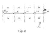
- first to fourth route sections 21 to 24 are counted from the current vehicle position in the destination direction.
- first to fourth optimization sections 31 to 34 are counted from the destination.
- the ViaArea route search is illustrated as a flowchart in FIG. 9 and subdivided into the following parts: start in step 50, initialization of the route table in step 51, initialization of the ViaAreas in step 52, optimization of the edges of the graph in step 53, determine if all sections are optimized in step 54 if NO in step 54 (path 58) update the ViaArea list in step 55 if YES in step 54 (path 59) Compile the route list in step 56 and end in step 57.
- the method of the ViaArea route search is based on a Bestweg algorithm according to Ford, Moore, where a route table is used to describe the properties of the edges of the graph.
- a route table is provided for each section, hereinafter referred to as route section table.
- the VAL is used for reference between these route section tables.
- two lists are provided for storing the edges to be optimized and those already optimized.
- the route table contains the description of the properties of all network edges with respect to a portion of the route to the destination. Each edge is represented by an entry that contains the properties of the edge both in the direction of the arrow and in the opposite direction.
- the following table illustrates a basic initialized route table for M edges.
- Tab. 6 Basic initialized route table edge + resistance + Successor edge -Resistance -Nach discountedkante k 1 ⁇ - ⁇ - k 2 ⁇ - ⁇ - k 3 ⁇ - ⁇ - ... k M-1 ⁇ - ⁇ - k M ⁇ - ⁇ -
- each route section is described in a separate route table, since the resistance of one edge and the successor to the destination may be different for different sections.
- ViaAreas The description of the ViaAreas and the connection to the associated edges in the graph is made by the linked ViaArealndex tables (VAIT) and ViaArea-DescriptionList (VADL).
- the VAIT contains all ViaAreas.
- the order of entries in this table determines the order in the route (ViaArea 1 is the first ViaArea of the route, etc.).
- the first entry does not contain a ViaArea but only serves to reference the route table of the first route section.
- the last entry in the VAIT is the actual destination, so the flow control in the route search simplifies.
- Each ViaArea is assigned a route table in the VAIT. Since the last entry corresponds to the destination and thus has no corresponding section, no route section table is assigned as agreed.
- Tab. 7 Structure of the ViaArealndexTable (VAIT) ViaArea Index Reference to the VADL route table - 1 1 2 2 3 3 4 ... ... N-1 N N -
- VADL ViaArea belonging edges
- the resistance to the target is stored for each of the two directions.
- the resistance is set to infinity for both directions.
- Tab. 8 Structure of the ViaAreaDescriptionList (VADL) index edge follow index ViaArea Index + resistance -Resistance 1 ⁇ ⁇ 2 ⁇ ⁇ 3 ⁇ ⁇ ... M ⁇ ⁇
- Fig. 10 illustrates the relationship of VAIT and VADL.
- Each ViaArea (VA) 14 of a VAIT 16 is associated with corresponding edges in the VADL 18.
- the first entry 60 of the VAIT is empty.
- the first ViaArea 61 are assigned the edges K1 (VA1) 70 and K2 (VA1) 71.
- the second ViaArea 62 are assigned the edges K1 (VA2) 72, K2 (VA2) 73 and K3 (VA2) 74.
- the third ViaArea 63 are assigned the edges K1 (VA3) 75 and K2 (VA3) 76.
- the (N-1) th ViaArea 64 are the edges K1 (VA (N-1)) 77, K2 (VA (N-1)) 78 and K3 (VA (N-1)) 79 are assigned.
- the Nth ViaArea 65 corresponds to the destination, and the edges K1 (destination) 80, K2 (destination) 81, K2 (destination) 82, and K3 (destination) 83 are assigned thereto.
- the optimization of the ViaArea route search corresponds in part to the optimization of a conventional route search.
- the list 1 is used.
- List 2 contains the edges to be checked in the next optimization step. From an actual edge all Ankommer edges are checked, as previously explained in more detail with reference to FIG. Since in the ViaArea route search according to the invention each section is optimized in a separate route table, the condition for optimizing the conventional route search can be used.
- the route search according to the invention or the optimization of the edges of the graph will be explained in greater detail.
- the resistance is set to infinity and the successor deleted (see Table 6).
- the resistance of the edges of the last via area from the VADL (see Table 8) is entered into the route table and the edges are included in the list of edges to be optimized.
- the successor of these edges is set to the initialization value, ie no successor, to represent that the further route description is to be found in the route table of the next route section.
- the last entry of the VAIT (see Table 7) is used. According to the agreement, this is the target itself, so that no special treatment is required for the first optimization stage.
- the respective edge must be optimized if the sum of the resistance of the actual edge entered in the route table and the edge resistance of the incoming edge is smaller than the old resistance of the incoming edge registered in the route table. If the result of this check is "YES”, it continues with branch 92, if the result of this check is "NO”, it continues with branch 93. In branch 92, at step 94, the corresponding entry in the route table is updated, updating the resistance of the incoming edge in the route table and entering the actual edge as the trailing edge. In step 95, the edge optimization ends.
- the edge optimization according to FIG. 11 is carried out for all edges entered in list 1. If all these edges have been processed accordingly, the list 1 and the list 2 are exchanged, ie the starting point for the next optimization are the edges optimized in the last step. The procedure terminates when list 1 is found empty.
- the VAL is updated in the following way.
- the resistance values of the via area of the following section in the VADL are updated. These values represent the starting point for optimizing the next section. If the next section is the last section to be optimized, ie the first section of the route, the next step is not the updating of the VAL but the following step:
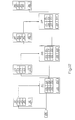
- the route list is generated from the individual route tables of the individual sections and the VAL. Starting from the edge of the current vehicle position (starting point), the edges are written to the route list according to the successor chaining in the first route table. The following ViaArea is reached at the first edge without successors. According to the VAIT, the route table of the next route section is determined. In this, starting from the last processed edge, the concatenation in the target direction continues to the next edge without successor. This procedure is performed for each section. In the last route section, the edge without successor corresponds to the target edge itself. In the VAIT there is no reference to another route table, so that the compilation of the route list is terminated.
- the route starts at start 100 (starting point) and by merging the individual route tables 110, 120 and 130 of the respective route sections 1, 2 and 3 according to the references in the VAL 102 current to the various route searches, the route is composed.
- the VAL contains the entries "VA -" 103, "VA 1" 104, "VA 2" 105 for respective ViaAreas (VA) and "Destination” 106.
- the route tables 110, 120, 130 each contain the entries for edges + k1 , + k2, + k3 ... + kn 141 to 144 and -k1, -k2, -k3 ... -kn 151 to 154.
- ViaAreaindexTable (VAIT) according to ViaArea and target definition ViaArea Index Reference to the VADL route table - - 1 1 2 2 2 1 - index edge follow index ViaArea Index + resistance -Resistance 1 k 8 - 2 0 0 2 k 4 3 1 ⁇ ⁇ 3 k 5 4 1 ⁇ ⁇ 4 k 6 - 1 ⁇ ⁇
- the current section is the first section to be optimized so that the last entry of the VAIT must be used. According to the agreement, this is the target itself.
- the resistance of the edges of the target from the VADL is entered in the route table and the edges are added to list 1 (Table 13) of the edges to be optimized.
- the result is the following route table according to Tab 12 .: Tab.
- optimization step 1 the optimization steps O1a 161, O1b 162 and O1c 163 illustrated in FIG. 13 are carried out.
- the new resistance value of the incoming edge is compared with the old value of that edge according to the optimization condition ( Figure 11).
- Table 16 Route table after optimization step 1 edge + resistance + Successor edge -Resistance -Nach discountedkante k 1 ⁇ - ⁇ - k 2 ⁇ - ⁇ - k 3 ⁇ - ⁇ - k 4 ⁇ - ⁇ - k 5 ⁇ - ⁇ - k 6 ⁇ - ⁇ - k 7 10 + k 8 ⁇ - k 8 0 - 0 - + k 7
- list 1 and list 2 are interchanged according to tab. 19 and 20.
- optimization step 2 the optimization steps 02a 164 and 02b 165 illustrated in FIG. 14 take place with edges according to the following table 21: Table 21: Optimization step 2 optimization step is-edge Ank-edge O2a + k 7 -k 7 O2b + k 7 + k 6
- the optimization steps O2a 164 O2b 165 essentially correspond to those of optimization step 1, so that they are not explained in more detail.
- Table 22 Route table after the optimization step 2 edge + resistance + Successor edge -Resistance -Nach discountedkante k 1 ⁇ - ⁇ - k 2 ⁇ - ⁇ - k 3 ⁇ - ⁇ - k 4 ⁇ - ⁇ - k 5 ⁇ - ⁇ - k 6 20 + k 7 ⁇ - k 7 10 + k 8 20 + k 7 k 8 0 - 0 - + k 6 -k 7
- optimization step 3 the optimization steps O3a 166, O3b 167, O3c 168, O3d 169 and O3e 170 illustrated in FIG. 15 take place with edges according to the following table 27: Tab. 27: Optimization step 3 optimization step Actual edge Ank-edge O3a + k 6 -k 6 O3b + k 6 + k 2 O3C + k 6 + k 5 o3d -k 7 + k 7 O3e -k 7 -k 8
- the new resistance value of the incoming edge is compared with the old value of that edge according to the optimization condition ( Figure 11).
- Table 28 Route table after the optimization step 3 edge + resistance + Successor edge -Resistance -Nach discountedkante k 1 ⁇ - ⁇ - k 2 35 + k 6 ⁇ - k 3 ⁇ - ⁇ - k 4 ⁇ - ⁇ - k 5 30 + k 6 ⁇ - k 6 20 + k 7 30 + k 6 k 7 10 + k 8 20 + k 7 k 8 0 - 0 - + k 2 + k 5 -k 6
- list 1 and list 2 are again interchanged according to tab. 31 and 32.
- optimization step 4 the optimization steps O4a 171, O4b 172, O4c 173, O4d 174, O4e 175, O4f 176 and O4g 177 illustrated in FIG. 16 take place with edges according to the following Table 33: Tab. 33: Optimization step 4 optimization step Actual edge Ank-edge O4a + k 2 -k 2 o4b + k 2 -k 3 O4c + k 2 + k 1 O4d + k 5 -k 5 O4e + k 5 + k 4 O4F -k 6 + k 6 O4g -k 6 -k 7
- Table 34 Route table after the optimization step 4 edge + resistance + Successor edge -Resistance -Nach discountedkante k 1 45 + k 2 ⁇ - k 2 35 + k 6 60 + k 2 k 3 ⁇ - 45 + k 2 k 4 40 + k 5 ⁇ - k 5 30 + k 6 40 + k 5 k 6 20 + k 7 30 + k 6 k 7 10 + k 8 20 + k 7 k 8 0 - 0 - + k 1 -k 2 -k 3 + k 4 -k 5
- list 1 and list 2 are again interchanged according to tab. 37 and 38.
- Table 37 List 1 before the optimization step 5 + k 1 -k 2 -k 3 + K 4 -k 5
- optimization step 5 the optimization steps O5a 178, O5b 179, O5c 180, O5d181, O5e182, O5f183, O5g184, O5h185, O5i186, O5k187 and O5188 illustrated in FIG. 17 are performed with edges according to the following Table 39: Tab.
- optimization step 5 optimization step Actual edge Ank-edge O5a + k 1 -k 1 O5b -k 2 + k 2 O5C -k 2 -k 6 O5d -k 2 + k 5 O5e -k 3 + k 3 O5f -k 3 -k 4 O5G + k 4 -k 4 O5h + k 4 + k 3 O5i -k 5 + k 5 O5k -k 5 + k 2 O5l -k 5 -k 6
- Table 40 Intermediate state of the route table in optimization step 5 edge + resistance + Successor edge -Resistance -Nach discountedkante k 1 45 + k 2 55 + k 1 k 2 35 + k 6 60 + k 2 k 3 55 -k 3 45 + k 2 k 4 40 + k 5 55 -k 3 k 5 30 + k 6 40 + k 5 k 6 20 + k 7 30 + k 6 k 7 10 + k 8 20 + k 7 k 8 0 - 0 -
- the Ankommerkanten + k 3 and -k 4 represent in the following optimization steps 05g and 05h again Ankommer edges.
- the new resistance value of the incoming edges is compared with the old value of these edges according to the optimization condition ( Figure 11).
- Table 41 Route table after optimization step 5 edge + resistance + Successor edge -Resistance -Nach discountedkante k 1 45 + k 2 55 + k 1 k 2 35 + k 6 60 + k 2 k 3 50 + k 4 45 + k 2 k 4 40 + k 5 50 + k 4 k 5 30 + k 6 40 + k 5 k 6 20 + k 7 30 + k 6 k 7 10 + k 8 20 + k 7 k 8 0 - 0 - -k 1 + k 3 -k 4
- list 1 and list 2 are again interchanged according to tab. 37 and 38.
- Tab. 44 List 1 before the optimization step 6 -k 1 + k 3 -k 4
- optimization step 5 the optimization steps 06a 189, 06b 190, 06c 191, 06d 192, 06e 193, 06f 194, 06g 195 and 06h 196 illustrated in FIG. 18 take place according to the following table 46: Tab. 46: Optimization step 6 optimization step Actual edge Ank-edge O6a -k 1 + k 1 O6b -k 1 -k 3 O6c -k 1 -k 2 O6d + k 3 -k 3 O6e + k 3 -k 2 O6f + k 3 + k 1 O6g -k 4 + k 4 O6h -k 4 -k 5
- the list 2 and therefore the list of the edges to be checked is thus empty, so that the end criterion for the first section of the ViaArea route search according to the invention is fulfilled and terminated.
- the route table of this section (Tab. 47) is saved.
- the resistance values and successors of the ViaAreas of the last section updated in the VADL. These values represent the starting point for the optimization of the next section to be optimized.
- the result is the following VAL, according to Tab. 50 and 51 Tab. 50: ViaArealndexTable (VAIT) after optimization of the first section ViaArea Index Reference to the VADL route table - - 1 1 2 2 2 1 - index edge follow index ViaArea Index + resistance -Resistance 1 k 8 - 2 0 0 2 k 4 3 1 40 50 3 k 5 4 1 30 40 4 k 6 - 1 20 30
- optimization step 7 the optimization steps O7a 201, O7b 202, O7c 203, O7d 204, O7e 205, O7f 206, O7g 207 and O7h 208, O7i 209, O7k 210, O71 211, O7m 212, O7n 213 and O7c 202 illustrated in FIG O7o 214 with edges according to following table 56: Tab.
- optimization step 7 optimization step Actual edge Ank-edge O7a + k 4 -k 4 O7b + k 4 + k 3 O7c -k 4 + k 4 O7d -k 4 -k 5 O7e + k 5 -k 5 O7f + k 5 + k 4 O7g -k 5 + k 5 O7h -k 5 + k 2 O7i -k 5 -k 5 O7k10 + k 6 -k 6 O7111 + k 6 + k 2 O7m 12 + k 6 + k 5 O7n13 -k 6 + k 6 O7o14 -k 6 -k 7
- the new resistance value of the incoming edge is compared with the old value of that edge according to the optimization condition ( Figure 11).
- the new resistance value of the incoming edge is compared with the old value of that edge according to the optimization condition ( Figure 11).
- Tab. 57 Route table after the optimization step 7 edge + resistance + Successor edge -Resistance -Nach discountedkante k 1 ⁇ - ⁇ - k 2 35 + k 6 ⁇ - k 3 50 + k 4 ⁇ - k 4 40 - 50 - k 5 30 - 40 - k 6 20 - 30 - k 7 ⁇ - 40 -k 6 k 8 ⁇ - ⁇ - + k 2 + k 3 -k 7
- list 1 and list 2 are again interchanged according to tab. 60 and 61.
- Table 60 List 1 before the optimization step 8 + k 2 + k 3 -k 7
- optimization step 8 the optimization steps 08a 178, O8b 179, O8c 180, O8d181, O8e182, O8f183, O8g184 and O8h185 illustrated in FIG. 20 take place with edges in accordance with the following table 62: Tab. 62: Optimization step 8 optimization step is-edge Ank-edge O8a + k 2 -k 2 O8b + k 2 + k 1 O8c + k 2 -k 3 O8d + k 3 -k 3 O8e + k 3 -k 2 O8f + k 3 + k 1 O8g -k 7 + k 7 O8h -k 7 -k 8
- the new resistance value of the incoming edge is compared with the old value of that edge according to the optimization condition ( Figure 11).
- Tab. 63 Route table after the optimization step 8 edge + resistance + Successor edge -Resistance -Nach discountedkante k 1 45 + k 2 ⁇ - k 2 35 + k 6 50 + k 2 k 3 50 + k 4 45 + k 2 k 4 40 - 50 - k 5 30 - 40 - k 6 20 - 30 - k 7 50 -k 7 40 -k 6 k 8 ⁇ - 50 -k 7 + k 1 -k 2 -k 3 + k 7 -k 8
- list 1 and list 2 are again interchanged according to tab. 66 and 67.
- Tab. 66 List 1 before the optimization step 9 + k 1 -k 2 -k 3 + k 7 -k 8
- optimization step 9 Optimization step Actual edge Ank-edge O9a + K -k 1 O9b -k 2 + k 2 O9c -k 2 -k 6 O9d -k 2 + k 5 O9e -k 3 + k 3 O9f -k 3 -k 4 O9g + k 7 -k 7 O9h + k 7 + k 6 O9i -k 8 + k 8
- Tab. 68 Route table after the optimization step 9 edge + resistance + Successor edge -Resistance -Nach discountedkante k 1 45 + k 2 55 + k 1 k 2 35 + k 6 50 + k 2 k 3 50 + k 4 45 + k 2 k 4 40 - 50 - k 5 30 - 40 - k 6 20 - 30 - k 7 50 -k 7 40 -k 6 k 8 60 -k 8 50 -k 7 -k 1 + k 8
- list 1 and list 2 are again interchanged according to tab. 71 and 72.
- optimization step 10 the optimization steps O10a 232, O10b 233, O10c 234, O10d 235, O10e 236 illustrated in FIG. 22 take place with edges according to the following table 73: Tab. 73: Optimization step 10 optimization step Actual edge Ank-edge O10a232 + k 1 -k 1 O10b233 -k 2 + k 2 O10c234 -k 2 -k 6 O10d235 -k 2 + k 5 O10e236 -k 3 + k 3
- Tab. 75 Route table after the optimization step 10 edge + resistance + Successor edge -Resistance -Nach discountedkante k 1 45 + k 2 55 + k 1 k 2 35 + k 6 50 + k 2 k 3 50 + k 4 45 + k 2 k 4 40 - 50 - k 5 30 - 40 - k 6 20 - 30 - k 7 50 -k 7 40 -k 6 k 8 60 -k 8 50 -k 7
- the list of edges to be checked is empty and thus meets the end criterion for the second and last section of the ViaArea route search according to the invention.
- the route list is compiled from the individual route tables of the individual sections and the VAL. Based on the edge of the current vehicle position, the edges are written to the route list according to the successor references in the route table of the last optimization section. It therefore starts with the route table of the first section according to Tab. 75, from which the edge + k 1 is taken and written as the first entry in the route list. In tab. 75, the edge + k 2 is entered as the successor so that it is written as the second entry in the route list. Successor of + k 2 is the edge + k 6 which is accordingly entered next in the route list. The edge + k 6 no longer has a successor, so that the evaluation of the route table of the first section according to Tab. 75 is completed.
- the route list now has the content shown in Tab. 78: Tab. 78: Route list of the first route section No. edge + Resistance to the goal Successor to the goal 1 + k 1 45 + k 2 2 + k 2 35 + k 6 3 + k 6 20 - 4 5 6
- the first viaArea is reached at the first edge without a follower, which in this case is the edge + k 6 .
- the route table of the next route section is determined. This is the route table of the second section according to Tab. 47.
- the last processed edge ie the edge + k 6
- the chaining in the target direction is continued until the next edge without a successor.
- the route list then has the content illustrated according to Tab. 79 Tab. 79: final route list of the ViaArea route No. edge + Resistance to the goal Successor to the goal 1 + k 1 45 + k 2 2 + k 2 35 + k 6 3 + k 6 20 + k 7 4 + k 7 10 + k 8 5 + k 8 0 - 6
- This ViaArea route has the course illustrated in FIG. 23.
- FIG. 24 illustrates in a flowchart the method according to the invention described above with reference to a concrete example.
- step 300 starts the inventive method.
- the destination and the viaAreas are defined.
- the VAL is generated with VAIT and VADL.
- the route table of the currently-edited section is initialized.
- the VAL is initialized with VAIT and VADL.
- the optimization of the edges of a section occurs.
- a query is made as to whether list 1 is empty. If "NO” goes to branch 306, if "YES” continues to branch 307.
- branch 306 in block 308, an actual edge is determined as the next edge in list 1.
- the incoming edges associated with this actual edge are subsequently determined.
- the edge optimization is performed according to the condition of FIG. 11.
- block 311 it is determined whether all the incoming edges have been processed. If “NO”, branch 312 returns to point 313 before block 309. If “YES”, branch 314 is continued and block 315 queries whether all edges from list 1 have been edited. If “NO”, branch 316 is jumped back to a point 317 before block 308. If “YES”, branch 318 is proceeded to, and in block 319, lists 1 and 2 are swapped. Thereafter, jump back to point 320 before block 305.
- list 1 is found empty, it continues to branch 307 and block 321, in which it is queried if all sections are optimized. If "NO”, branch 322 branches to block 323, where the VAL is updated. Subsequently, jump back to point 324 before block 302. If "YES" is determined in block 321, branch 325 continues to block 326 where the route list is collated. In block 327, the method then ends.
- FIG. 25 An apparatus 400 designed to carry out the method according to the invention is shown by way of example in FIG. 25.
- This includes a navigation computer 401, a mass data memory 402 containing the digital map as an image of the real road network, a sensor device 404, a location device 406, a route search device 408, an index memory 410, an interface 412, a speaker 414, a display device 416 and an input device 418 Interface 412 is extended according to the input and definition of ViaAreas.
- the index memory 410 is also extended according to the memory of the VAL with VAIT and VADL and the various route tables of the individual sections.
- 26 to 28 each show a road map 500 with roads 510 and locations 512 to 520.
- the illustrated road network exemplifies a real existing road network with the locations "Kassel” 512, “Minden” 514 “,” Hannover “516,” Braunschweig “518 and” Bielefeld "520.
- Each of the maps 500 includes, in addition to the roads 510, a calculated route 522 which is shown in bold line.
- Fig. 26 illustrates a situation in which only the starting point "Kassel” 512 and the destination "Minden” 514 "have been set for route calculation, in other words, a" normal "route is the calculated route has a length of 176 km and requires an estimated travel time of 1:44 h
- the route list has the following content: "City Kassel, A44, A33, A2 and surroundings Minden”.
- the intermediate destination "Hannover” 516 in addition to the starting point "Kassel” 512 and the destination "Minden” 514 " specified and then calculated the route.
- This situation is illustrated in FIG. 27.
- first a first route from "Kassel” 512 to "Hannover” 516 is calculated, then a separate second route from "Hannover” 516 to "Minden” 514 is calculated and then these two routes are simply put together.
- the first route has a length of 165 km with an estimated journey time of 1:36 h.
- the second route has a length of 75 km with an estimated journey time of 0:55 h.
- the total route 522 then has a length of 240 km and an estimated driving time of 2:32 h.
- the following is entered in the route list: "City area Kassel, A7, Hannover (city thoroughfare), A2, surroundings of Minden”.
- FIG. 27 The comparison of Figs. 28 and 28a with Figs. 27 and 27a, respectively, clearly illustrates the difference between the invention and the conventional inter-destination route calculation method.
- the conventional method of FIG. 27 can not account for the onward journey from "Hannover” 516 to "Minden” 514, and therefore chooses a route into the city of "Hannover” 516, as if "Hannover" 516 was the final destination.
- the method according to the invention in the transition region 524 of the intermediate destination "Hannover" 516 selects a route which is optimized with respect to the onward journey to "Minden" 514.
Landscapes
- Engineering & Computer Science (AREA)
- Radar, Positioning & Navigation (AREA)
- Remote Sensing (AREA)
- Business, Economics & Management (AREA)
- Physics & Mathematics (AREA)
- General Physics & Mathematics (AREA)
- Human Resources & Organizations (AREA)
- Automation & Control Theory (AREA)
- Strategic Management (AREA)
- Economics (AREA)
- Game Theory and Decision Science (AREA)
- Development Economics (AREA)
- Entrepreneurship & Innovation (AREA)
- Marketing (AREA)
- Operations Research (AREA)
- Quality & Reliability (AREA)
- Tourism & Hospitality (AREA)
- General Business, Economics & Management (AREA)
- Theoretical Computer Science (AREA)
- Navigation (AREA)
- Instructional Devices (AREA)
Applications Claiming Priority (3)
| Application Number | Priority Date | Filing Date | Title |
|---|---|---|---|
| DE19928295 | 1999-06-22 | ||
| DE19928295A DE19928295A1 (de) | 1999-06-22 | 1999-06-22 | Verfahren und Vorrichtung zum Bestimmen einer Route von einem Ausgangsort zu einem Zielort |
| PCT/DE2000/001874 WO2000079219A1 (de) | 1999-06-22 | 2000-06-08 | Verfahren und vorrichtung zum bestimmen einer route von einem ausgangsort zu einem zielort |
Publications (2)
| Publication Number | Publication Date |
|---|---|
| EP1105696A1 EP1105696A1 (de) | 2001-06-13 |
| EP1105696B1 true EP1105696B1 (de) | 2007-03-28 |
Family
ID=7911966
Family Applications (1)
| Application Number | Title | Priority Date | Filing Date |
|---|---|---|---|
| EP00945618A Expired - Lifetime EP1105696B1 (de) | 1999-06-22 | 2000-06-08 | Verfahren und vorrichtung zum bestimmen einer route von einem ausgangsort zu einem zielort |
Country Status (6)
| Country | Link |
|---|---|
| US (1) | US6567743B1 (ja) |
| EP (1) | EP1105696B1 (ja) |
| JP (1) | JP4673530B2 (ja) |
| AU (1) | AU765064B2 (ja) |
| DE (2) | DE19928295A1 (ja) |
| WO (1) | WO2000079219A1 (ja) |
Cited By (1)
| Publication number | Priority date | Publication date | Assignee | Title |
|---|---|---|---|---|
| DE102007054875A1 (de) | 2007-11-15 | 2009-05-20 | Navigon Ag | Verfahren zum Betrieb einer Navigationseinrichtung |
Families Citing this family (71)
| Publication number | Priority date | Publication date | Assignee | Title |
|---|---|---|---|---|
| US20030009280A1 (en) * | 2001-01-05 | 2003-01-09 | Alcatel | Navigation method and navigation system |
| DE10128517A1 (de) * | 2001-06-13 | 2003-01-02 | Vodafone Ag | Verfahren zum Erzeugen von Navigationsdaten für eine Routenführung sowie Navigationssystem |
| DE10137632A1 (de) * | 2001-08-03 | 2003-02-27 | Daimler Chrysler Ag | Verfahren und System zum Auffinden eines Ortes in einer digitalen Karte |
| DE10139549A1 (de) * | 2001-08-10 | 2003-03-06 | Bosch Gmbh Robert | Verfahren zum Ermitteln von Routen und darauf bezogenes Navigationssystem |
| DE10145299A1 (de) | 2001-09-14 | 2003-04-03 | Bosch Gmbh Robert | Verfahren zur automatischen Berechnung von optimalen Routen |
| US6704645B1 (en) * | 2001-12-11 | 2004-03-09 | Garmin Ltd. | System and method for estimating impedance time through a road network |
| US6975940B1 (en) * | 2001-12-21 | 2005-12-13 | Garmin Ltd. | Systems, functional data, and methods for generating a route |
| US7184886B1 (en) * | 2001-12-21 | 2007-02-27 | Garmin Ltd. | Navigation system, method and device with detour algorithm |
| DE10218340A1 (de) * | 2002-04-24 | 2003-11-13 | Siemens Ag | Navigationssystem und Verfahren zur Routenbestimmung |
| JP2004108803A (ja) * | 2002-09-13 | 2004-04-08 | Pioneer Electronic Corp | ナビゲーション端末、ナビゲーションシステム、そのプログラム、及び走行案内方法 |
| DE10329507A1 (de) * | 2003-06-30 | 2005-02-10 | Siemens Ag | Verfahren und Navigationssystem zur Routenbestimmung mit Zwischenzielen |
| US8165969B2 (en) * | 2003-07-31 | 2012-04-24 | Cisco Technology, Inc. | Route optimization of services provided by one or more service providers for combined links |
| CN1823259B (zh) * | 2003-08-18 | 2010-06-23 | 松下电器产业株式会社 | 导航设备 |
| ATE347089T1 (de) * | 2004-05-27 | 2006-12-15 | Delphi Tech Inc | Kraftfahrzeugnavigationsgerät |
| US7158876B2 (en) * | 2004-08-13 | 2007-01-02 | Hubert W. Crook Computer Consultants, Inc. | Automated vehicle routing based on physical vehicle criteria |
| WO2006042688A2 (fr) * | 2004-10-18 | 2006-04-27 | Societe De Technologie Michelin | Procede d’etablissement de points de voisinage pour systeme de reseau routier numerique |
| EP1805484B1 (fr) * | 2004-10-18 | 2018-05-23 | Compagnie Générale des Etablissements Michelin | Procede et dispositif de calcul d'itineraire avec elimination progressive des donnees correspondant au reseau routier |
| US8073968B1 (en) * | 2004-11-03 | 2011-12-06 | Cisco Technology, Inc. | Method and apparatus for automatically optimizing routing operations at the edge of a network |
| US20060161337A1 (en) * | 2005-01-19 | 2006-07-20 | Ping-Chung Ng | Route planning process |
| DE102005004635A1 (de) * | 2005-02-01 | 2006-08-10 | Siemens Ag | System zur abschnittsweisen Bestimmung einer Route |
| FR2881862B1 (fr) * | 2005-02-07 | 2007-04-13 | Michelin Soc Tech | Procede et dispositif de determination d'itineraire avec points d'interet |
| US20070073897A1 (en) * | 2005-06-21 | 2007-03-29 | Mehdi Sharifzadeh | Optimal sequenced route query operation and device |
| US7698061B2 (en) | 2005-09-23 | 2010-04-13 | Scenera Technologies, Llc | System and method for selecting and presenting a route to a user |
| US20110184770A1 (en) * | 2005-12-07 | 2011-07-28 | Winfried Schwarzmann | Cross docking in route determination |
| US7925320B2 (en) | 2006-03-06 | 2011-04-12 | Garmin Switzerland Gmbh | Electronic device mount |
| US7702456B2 (en) * | 2006-04-14 | 2010-04-20 | Scenera Technologies, Llc | System and method for presenting a computed route |
| ATE451595T1 (de) * | 2006-06-13 | 2009-12-15 | Harman Becker Automotive Sys | Bestimmung einer optimalen route mittels einer schätzungsfunktion |
| US8649899B2 (en) * | 2006-06-19 | 2014-02-11 | Amazon Technologies, Inc. | System and method for maneuvering a mobile drive unit |
| US7873469B2 (en) | 2006-06-19 | 2011-01-18 | Kiva Systems, Inc. | System and method for managing mobile drive units |
| US20130302132A1 (en) | 2012-05-14 | 2013-11-14 | Kiva Systems, Inc. | System and Method for Maneuvering a Mobile Drive Unit |
| US8538692B2 (en) * | 2006-06-19 | 2013-09-17 | Amazon Technologies, Inc. | System and method for generating a path for a mobile drive unit |
| US7912574B2 (en) | 2006-06-19 | 2011-03-22 | Kiva Systems, Inc. | System and method for transporting inventory items |
| US8220710B2 (en) | 2006-06-19 | 2012-07-17 | Kiva Systems, Inc. | System and method for positioning a mobile drive unit |
| US7920962B2 (en) | 2006-06-19 | 2011-04-05 | Kiva Systems, Inc. | System and method for coordinating movement of mobile drive units |
| US7610151B2 (en) * | 2006-06-27 | 2009-10-27 | Microsoft Corporation | Collaborative route planning for generating personalized and context-sensitive routing recommendations |
| US8793066B2 (en) * | 2006-06-27 | 2014-07-29 | Microsoft Corporation | Route monetization |
| US8036822B2 (en) * | 2006-09-12 | 2011-10-11 | Dds Wireless International Inc. | Travel time determination |
| JP4956126B2 (ja) * | 2006-09-29 | 2012-06-20 | キヤノン株式会社 | 画像形成装置および画像形成装置における通知方法 |
| US7447588B1 (en) | 2007-07-16 | 2008-11-04 | Wenshine Technology Ltd. | Method and system for partitioning a continental roadway network for an intelligent vehicle highway system |
| US20090112843A1 (en) * | 2007-10-29 | 2009-04-30 | International Business Machines Corporation | System and method for providing differentiated service levels for search index |
| DE102007052155A1 (de) | 2007-10-31 | 2009-05-07 | Robert Bosch Gmbh | Navigationssystem und Verfahren zur Routenermittlung |
| DE102007056328A1 (de) * | 2007-11-22 | 2009-05-28 | Robert Bosch Gmbh | Verfahren und Vorrichtung zum Bereitstellen einer Information über interessante Orte mit einem Navigationssystem |
| US8090532B2 (en) | 2007-12-14 | 2012-01-03 | Microsoft Corporation | Pedestrian route production |
| US8060297B2 (en) | 2007-12-14 | 2011-11-15 | Microsoft Corporation | Route transfer between devices |
| US8428859B2 (en) * | 2007-12-14 | 2013-04-23 | Microsoft Corporation | Federated route production |
| US8473198B2 (en) | 2007-12-14 | 2013-06-25 | Microsoft Corporation | Additional content based on intended travel destination |
| US8676489B2 (en) * | 2008-02-07 | 2014-03-18 | Microsoft Corporation | Positioning map views to show more optimal route information |
| US8793065B2 (en) | 2008-02-19 | 2014-07-29 | Microsoft Corporation | Route-based activity planner |
| US20090326799A1 (en) * | 2008-06-25 | 2009-12-31 | Expresspass Systems, Inc. | Distributed Route Segment Maintenance and Hierarchical Routing Based on Physical Vehicle Criteria |
| US8219317B2 (en) * | 2008-09-22 | 2012-07-10 | Mitac International Corporation | Route navigation via a proximity point |
| US8219316B2 (en) | 2008-11-14 | 2012-07-10 | Google Inc. | System and method for storing and providing routes |
| TW201022633A (en) * | 2008-12-11 | 2010-06-16 | Mitac Int Corp | Route planning methods and systems, and machine readable medium and computer program products thereof |
| US20120047087A1 (en) | 2009-03-25 | 2012-02-23 | Waldeck Technology Llc | Smart encounters |
| WO2011124271A1 (en) | 2010-04-09 | 2011-10-13 | Tomtom International B.V. | Method of generating a route |
| DE102010035373A1 (de) * | 2010-08-25 | 2012-03-01 | Elektrobit Automotive Gmbh | Technik zur bildschirmbasierten Routenmanipulation |
| BR112013007400A2 (pt) | 2010-09-29 | 2018-05-02 | Aharonian Gregory | escritórios ou resistências em uma estrutura urbana flutuantes para partes independentes de navegação |
| DE102010051541A1 (de) | 2010-11-18 | 2012-05-24 | Navigon Ag | Routenmagnet |
| DE102012200192A1 (de) * | 2012-01-09 | 2013-07-11 | Robert Bosch Gmbh | Verfahren und Vorrichtung zum Betreiben eines Fahrzeugs |
| DE102012001163A1 (de) | 2012-01-21 | 2013-07-25 | Volkswagen Aktiengesellschaft | Verfahren und Vorrichtung zum Bestimmen einer zu fahrenden Navigationsroute eines Fahrzeugs |
| JP5950206B2 (ja) * | 2012-07-30 | 2016-07-13 | アイシン・エィ・ダブリュ株式会社 | ナビゲーション装置及びナビゲーションプログラム |
| US9304007B2 (en) * | 2013-08-13 | 2016-04-05 | Mapquest, Inc. | Systems and methods for providing mapping services including route break point recommendations |
| US11118934B2 (en) * | 2015-02-25 | 2021-09-14 | Alpine Electronics, Inc. | Method and system of route guidance for a towing vehicle |
| US9639995B2 (en) | 2015-02-25 | 2017-05-02 | Snap-On Incorporated | Methods and systems for generating and outputting test drive scripts for vehicles |
| US10002471B2 (en) * | 2015-09-30 | 2018-06-19 | Ants Technology (Hk) Limited | Systems and methods for autonomous vehicle navigation |
| EP3225954B1 (en) | 2016-03-28 | 2019-03-13 | TomTom Navigation B.V. | Generating routes using electronic map data |
| US11092446B2 (en) | 2016-06-14 | 2021-08-17 | Motional Ad Llc | Route planning for an autonomous vehicle |
| US10309792B2 (en) * | 2016-06-14 | 2019-06-04 | nuTonomy Inc. | Route planning for an autonomous vehicle |
| FR3058817A1 (fr) * | 2016-11-14 | 2018-05-18 | Pierre Zeboulon | Procede et dispositif de determination d'un itineraire privilegie |
| US10990911B2 (en) | 2018-01-18 | 2021-04-27 | Target Brands, Inc. | Delivery route management and optimization |
| CN113485363B (zh) * | 2021-08-02 | 2024-02-20 | 安徽理工大学 | 基于膜计算和rrt的煤矿井下机器人多步长路径规划方法 |
| US11747153B1 (en) | 2022-07-21 | 2023-09-05 | Travelshift ehf. | Apparatus and associated method for determining a travel itinerary |
Family Cites Families (20)
| Publication number | Priority date | Publication date | Assignee | Title |
|---|---|---|---|---|
| DE69129892T2 (de) * | 1990-11-09 | 1999-03-18 | Sumitomo Electric Industries | Vorrichtung für eine günstige Route-Auswahl |
| JP2679505B2 (ja) | 1992-01-22 | 1997-11-19 | 三菱電機株式会社 | 移動体用ナビゲーション装置 |
| JPH0727568A (ja) * | 1993-07-09 | 1995-01-27 | Zanabui Informatics:Kk | 経路誘導装置および経路探索方法 |
| JP3045013B2 (ja) * | 1994-09-16 | 2000-05-22 | 住友電気工業株式会社 | ナビゲーション装置 |
| US5938720A (en) | 1995-02-09 | 1999-08-17 | Visteon Technologies, Llc | Route generation in a vehicle navigation system |
| US5712788A (en) * | 1995-02-09 | 1998-01-27 | Zexel Corporation | Incremental route calculation |
| JP3381459B2 (ja) * | 1995-05-30 | 2003-02-24 | 株式会社デンソー | 車両用走行案内装置 |
| US5933100A (en) * | 1995-12-27 | 1999-08-03 | Mitsubishi Electric Information Technology Center America, Inc. | Automobile navigation system with dynamic traffic data |
| JP3173983B2 (ja) * | 1995-12-28 | 2001-06-04 | 松下電器産業株式会社 | 経路選出方法およびシステム |
| JP3769817B2 (ja) * | 1996-06-05 | 2006-04-26 | 松下電器産業株式会社 | 経路探索表示装置 |
| US6026346A (en) * | 1996-11-27 | 2000-02-15 | Honda Giken Kogyo Kabushiki Kaisha | Navigation system for indicating of optimum route |
| JP3270383B2 (ja) * | 1997-01-29 | 2002-04-02 | 松下電器産業株式会社 | 経路選出方法およびシステム |
| DE69833139T2 (de) * | 1997-01-29 | 2006-10-05 | Matsushita Electric Industrial Co., Ltd., Kadoma | Verfahren und Vorrichtung zur Routensuche |
| US6112154A (en) * | 1997-05-22 | 2000-08-29 | Siemens Aktiengesellschaft | Method and apparatus for determining a route on a digitized road network stored in the memory of a navigation system |
| JP3371768B2 (ja) * | 1997-08-29 | 2003-01-27 | 株式会社デンソー | 車両用走行経路案内装置およびその地図データ記録媒体 |
| US6192314B1 (en) * | 1998-03-25 | 2001-02-20 | Navigation Technologies Corp. | Method and system for route calculation in a navigation application |
| JP2000088594A (ja) * | 1998-09-16 | 2000-03-31 | Denso Corp | 車両用ナビゲーション装置 |
| JP3750400B2 (ja) * | 1999-03-08 | 2006-03-01 | 株式会社ナビタイムジャパン | 交通ネットワーク経路探索方法および装置 |
| US6256579B1 (en) * | 1999-07-13 | 2001-07-03 | Alpine Electronics, Inc. | Vehicle navigation system with road link re-costing |
| US6401034B1 (en) * | 1999-09-02 | 2002-06-04 | Navigation Technologies Corp. | Method and system for finding intermediate destinations with a navigation system |
-
1999
- 1999-06-22 DE DE19928295A patent/DE19928295A1/de not_active Ceased
-
2000
- 2000-06-08 DE DE50014194T patent/DE50014194D1/de not_active Expired - Lifetime
- 2000-06-08 WO PCT/DE2000/001874 patent/WO2000079219A1/de active IP Right Grant
- 2000-06-08 US US09/762,709 patent/US6567743B1/en not_active Expired - Lifetime
- 2000-06-08 AU AU59640/00A patent/AU765064B2/en not_active Ceased
- 2000-06-08 EP EP00945618A patent/EP1105696B1/de not_active Expired - Lifetime
- 2000-06-08 JP JP2001505533A patent/JP4673530B2/ja not_active Expired - Lifetime
Cited By (2)
| Publication number | Priority date | Publication date | Assignee | Title |
|---|---|---|---|---|
| DE102007054875A1 (de) | 2007-11-15 | 2009-05-20 | Navigon Ag | Verfahren zum Betrieb einer Navigationseinrichtung |
| WO2009062458A1 (de) | 2007-11-15 | 2009-05-22 | Navigon Ag | Verfahren zum betrieb einer navigationseinrichtung |
Also Published As
| Publication number | Publication date |
|---|---|
| JP2003502680A (ja) | 2003-01-21 |
| WO2000079219A1 (de) | 2000-12-28 |
| US6567743B1 (en) | 2003-05-20 |
| DE19928295A1 (de) | 2000-12-28 |
| AU765064B2 (en) | 2003-09-04 |
| AU5964000A (en) | 2001-01-09 |
| DE50014194D1 (de) | 2007-05-10 |
| JP4673530B2 (ja) | 2011-04-20 |
| EP1105696A1 (de) | 2001-06-13 |
Similar Documents
| Publication | Publication Date | Title |
|---|---|---|
| EP1105696B1 (de) | Verfahren und vorrichtung zum bestimmen einer route von einem ausgangsort zu einem zielort | |
| EP0979987B1 (de) | Verfahren zum Bestimmen einer Route von einem Ausgangspunkt zu einem Zielpunkt | |
| DE69935184T2 (de) | Verfahren und System zur Generierung einer Navigationsroute | |
| DE10162359B4 (de) | Verfahren zur Bereitstellung von Routendaten für ein Navigationsgerät | |
| EP1957940B1 (de) | Verfahren zur navigation mindestens eines fortbewegungsmittels | |
| DE4035979A1 (de) | Navigationssystem fuer kraftfahrzeuge | |
| EP1141910B2 (de) | Navigationsverfahren und navigationssystem für fortbewegungsmittel | |
| EP2507589B1 (de) | Verfahren zur vereinfachung einer beschreibung einer fahrtroute | |
| DE10031535B4 (de) | Karteninformationsanzeigeeinrichtung für einen sich bewegenden Körper und Verfahren zur Anzeige von Karteninformation für einen sich bewegenden Körper | |
| DE19703436A1 (de) | Fahrzeuggebundene Wegesuchvorrichtung und Wegesuchverfahren | |
| EP1423661B1 (de) | Verfahren zum ermitteln von routen und darauf bezogenes navigationssystem | |
| EP1430273B1 (de) | Verfahren zur automatischen berechnung von optimalen routen | |
| DE102009047410A1 (de) | Verfahren und Navigationsgerät zum dynamischen Ermitteln eines Routenverlaufs | |
| EP3069103A1 (de) | Navigationssystem und verfahren zu seinem betrieb | |
| EP1357359B1 (de) | Navigationssystem und Verfahren zur Routenbestimmung | |
| EP1533592A1 (de) | Verfahren zur Auswahl und Aufbereitung von Verkehrsinformationen | |
| DE102017217747A1 (de) | Verfahren zum Betrieb eines Navigationssystems | |
| EP1092950A1 (de) | Verfahren zur Bestimmung einer Fahrtroute für ein Strassenfahrzeug | |
| EP3555570A2 (de) | Verfahren zum bereitstellen einer textbasierten beschreibung zumindest einer route für eine fahrt eines kraftfahrzeugs sowie steuervorrichtung und kraftfahrzeug | |
| DE102013209168A1 (de) | Verfahren zum Betreiben eines Navigationssystems, Navigationssystem und Kraftfahrzeug | |
| DE102021100250A1 (de) | Durch crowdsourcing erhaltene navigationssysteme und -verfahren | |
| DE102012025510A1 (de) | Routenprädiktionsverfahren | |
| EP1359393B1 (de) | Kraftfahrzeugnavigationssystem und Verfahren zur Auswahl einer Bezeichnung | |
| DE102004032499B3 (de) | Verfahren und Routenplanungssystem zur Generierung und Speicherung von für eine dynamische Routenplanung benötigten Daten | |
| EP1494193B1 (de) | Verfahren und Navigationssystem zur Routenbestimmung mit Zwischenzielen |
Legal Events
| Date | Code | Title | Description |
|---|---|---|---|
| PUAI | Public reference made under article 153(3) epc to a published international application that has entered the european phase |
Free format text: ORIGINAL CODE: 0009012 |
|
| AK | Designated contracting states |
Kind code of ref document: A1 Designated state(s): AT BE CH CY DE DK ES FI FR GB GR IE IT LI LU MC NL PT SE |
|
| AX | Request for extension of the european patent |
Free format text: AL;LT;LV;MK;RO;SI |
|
| 17P | Request for examination filed |
Effective date: 20010628 |
|
| RBV | Designated contracting states (corrected) |
Designated state(s): DE FR GB IT |
|
| 17Q | First examination report despatched |
Effective date: 20060714 |
|
| GRAP | Despatch of communication of intention to grant a patent |
Free format text: ORIGINAL CODE: EPIDOSNIGR1 |
|
| GRAS | Grant fee paid |
Free format text: ORIGINAL CODE: EPIDOSNIGR3 |
|
| GRAA | (expected) grant |
Free format text: ORIGINAL CODE: 0009210 |
|
| AK | Designated contracting states |
Kind code of ref document: B1 Designated state(s): DE FR GB IT |
|
| REG | Reference to a national code |
Ref country code: GB Ref legal event code: FG4D Free format text: NOT ENGLISH |
|
| REF | Corresponds to: |
Ref document number: 50014194 Country of ref document: DE Date of ref document: 20070510 Kind code of ref document: P |
|
| GBT | Gb: translation of ep patent filed (gb section 77(6)(a)/1977) |
Effective date: 20070702 |
|
| ET | Fr: translation filed | ||
| PLBE | No opposition filed within time limit |
Free format text: ORIGINAL CODE: 0009261 |
|
| STAA | Information on the status of an ep patent application or granted ep patent |
Free format text: STATUS: NO OPPOSITION FILED WITHIN TIME LIMIT |
|
| 26N | No opposition filed |
Effective date: 20080102 |
|
| REG | Reference to a national code |
Ref country code: GB Ref legal event code: 732E Free format text: REGISTERED BETWEEN 20140424 AND 20140430 |
|
| REG | Reference to a national code |
Ref country code: FR Ref legal event code: PLFP Year of fee payment: 16 |
|
| REG | Reference to a national code |
Ref country code: DE Ref legal event code: R081 Ref document number: 50014194 Country of ref document: DE Owner name: TOMTOM GLOBAL ASSETS B.V., NL Free format text: FORMER OWNER: ROBERT BOSCH GMBH, 70469 STUTTGART, DE |
|
| REG | Reference to a national code |
Ref country code: FR Ref legal event code: TP Owner name: TOMTOM GLOBAL ASSETS B.V., NL Effective date: 20160503 |
|
| REG | Reference to a national code |
Ref country code: FR Ref legal event code: PLFP Year of fee payment: 17 |
|
| REG | Reference to a national code |
Ref country code: FR Ref legal event code: PLFP Year of fee payment: 18 |
|
| REG | Reference to a national code |
Ref country code: FR Ref legal event code: PLFP Year of fee payment: 19 |
|
| PGFP | Annual fee paid to national office [announced via postgrant information from national office to epo] |
Ref country code: DE Payment date: 20190528 Year of fee payment: 20 Ref country code: IT Payment date: 20190620 Year of fee payment: 20 |
|
| PGFP | Annual fee paid to national office [announced via postgrant information from national office to epo] |
Ref country code: FR Payment date: 20190524 Year of fee payment: 20 |
|
| PGFP | Annual fee paid to national office [announced via postgrant information from national office to epo] |
Ref country code: GB Payment date: 20190605 Year of fee payment: 20 |
|
| REG | Reference to a national code |
Ref country code: DE Ref legal event code: R071 Ref document number: 50014194 Country of ref document: DE |
|
| REG | Reference to a national code |
Ref country code: GB Ref legal event code: PE20 Expiry date: 20200607 |
|
| PG25 | Lapsed in a contracting state [announced via postgrant information from national office to epo] |
Ref country code: GB Free format text: LAPSE BECAUSE OF EXPIRATION OF PROTECTION Effective date: 20200607 |