EP1104325B1 - Biomedical electrode with perforation lines - Google Patents
Biomedical electrode with perforation lines Download PDFInfo
- Publication number
- EP1104325B1 EP1104325B1 EP99939021A EP99939021A EP1104325B1 EP 1104325 B1 EP1104325 B1 EP 1104325B1 EP 99939021 A EP99939021 A EP 99939021A EP 99939021 A EP99939021 A EP 99939021A EP 1104325 B1 EP1104325 B1 EP 1104325B1
- Authority
- EP
- European Patent Office
- Prior art keywords
- pad
- biomedical electrode
- detaching
- biomedical
- electrode according
- Prior art date
- Legal status (The legal status is an assumption and is not a legal conclusion. Google has not performed a legal analysis and makes no representation as to the accuracy of the status listed.)
- Expired - Lifetime
Links
- 230000001681 protective effect Effects 0.000 claims abstract description 13
- 238000000926 separation method Methods 0.000 claims abstract description 12
- 239000000853 adhesive Substances 0.000 claims abstract description 11
- 230000001070 adhesive effect Effects 0.000 claims abstract description 11
- 239000002184 metal Substances 0.000 claims abstract description 4
- 239000011888 foil Substances 0.000 claims abstract description 3
- 239000010410 layer Substances 0.000 claims description 25
- 239000004820 Pressure-sensitive adhesive Substances 0.000 claims description 10
- 235000015110 jellies Nutrition 0.000 claims description 7
- 239000008274 jelly Substances 0.000 claims description 7
- 239000012790 adhesive layer Substances 0.000 claims description 5
- 238000000034 method Methods 0.000 claims description 4
- 239000006261 foam material Substances 0.000 claims 1
- 239000006260 foam Substances 0.000 abstract 1
- WABPQHHGFIMREM-UHFFFAOYSA-N lead(0) Chemical compound [Pb] WABPQHHGFIMREM-UHFFFAOYSA-N 0.000 description 5
- 238000012544 monitoring process Methods 0.000 description 5
- 239000012530 fluid Substances 0.000 description 4
- 239000000463 material Substances 0.000 description 4
- 238000013461 design Methods 0.000 description 3
- 230000002232 neuromuscular Effects 0.000 description 3
- 230000004936 stimulating effect Effects 0.000 description 3
- 230000000638 stimulation Effects 0.000 description 3
- 210000004556 brain Anatomy 0.000 description 2
- 210000003811 finger Anatomy 0.000 description 2
- 239000000499 gel Substances 0.000 description 2
- 210000005036 nerve Anatomy 0.000 description 2
- 239000004033 plastic Substances 0.000 description 2
- 229920003023 plastic Polymers 0.000 description 2
- -1 polyethylene Polymers 0.000 description 2
- 210000003813 thumb Anatomy 0.000 description 2
- 241000270728 Alligator Species 0.000 description 1
- 239000004698 Polyethylene Substances 0.000 description 1
- FAPWRFPIFSIZLT-UHFFFAOYSA-M Sodium chloride Chemical compound [Na+].[Cl-] FAPWRFPIFSIZLT-UHFFFAOYSA-M 0.000 description 1
- 206010061592 cardiac fibrillation Diseases 0.000 description 1
- 238000004891 communication Methods 0.000 description 1
- 239000004020 conductor Substances 0.000 description 1
- 238000010276 construction Methods 0.000 description 1
- 238000005520 cutting process Methods 0.000 description 1
- 238000001035 drying Methods 0.000 description 1
- 239000012777 electrically insulating material Substances 0.000 description 1
- 230000002600 fibrillogenic effect Effects 0.000 description 1
- 229920001821 foam rubber Polymers 0.000 description 1
- 238000004519 manufacturing process Methods 0.000 description 1
- 238000012806 monitoring device Methods 0.000 description 1
- 239000012811 non-conductive material Substances 0.000 description 1
- 239000002984 plastic foam Substances 0.000 description 1
- 229920000573 polyethylene Polymers 0.000 description 1
- 229920002635 polyurethane Polymers 0.000 description 1
- 239000004814 polyurethane Substances 0.000 description 1
- 239000011780 sodium chloride Substances 0.000 description 1
- 230000001225 therapeutic effect Effects 0.000 description 1
- 238000002646 transcutaneous electrical nerve stimulation Methods 0.000 description 1
- 238000012546 transfer Methods 0.000 description 1
Images

Classifications
-
- A—HUMAN NECESSITIES
- A61—MEDICAL OR VETERINARY SCIENCE; HYGIENE
- A61N—ELECTROTHERAPY; MAGNETOTHERAPY; RADIATION THERAPY; ULTRASOUND THERAPY
- A61N1/00—Electrotherapy; Circuits therefor
- A61N1/02—Details
- A61N1/04—Electrodes
- A61N1/0404—Electrodes for external use
- A61N1/0408—Use-related aspects
- A61N1/0456—Specially adapted for transcutaneous electrical nerve stimulation [TENS]
-
- A—HUMAN NECESSITIES
- A61—MEDICAL OR VETERINARY SCIENCE; HYGIENE
- A61N—ELECTROTHERAPY; MAGNETOTHERAPY; RADIATION THERAPY; ULTRASOUND THERAPY
- A61N1/00—Electrotherapy; Circuits therefor
- A61N1/02—Details
- A61N1/04—Electrodes
- A61N1/0404—Electrodes for external use
- A61N1/0472—Structure-related aspects
- A61N1/0492—Patch electrodes
-
- A—HUMAN NECESSITIES
- A61—MEDICAL OR VETERINARY SCIENCE; HYGIENE
- A61N—ELECTROTHERAPY; MAGNETOTHERAPY; RADIATION THERAPY; ULTRASOUND THERAPY
- A61N1/00—Electrotherapy; Circuits therefor
- A61N1/02—Details
- A61N1/04—Electrodes
- A61N1/0404—Electrodes for external use
- A61N1/0408—Use-related aspects
- A61N1/046—Specially adapted for shock therapy, e.g. defibrillation
-
- A—HUMAN NECESSITIES
- A61—MEDICAL OR VETERINARY SCIENCE; HYGIENE
- A61N—ELECTROTHERAPY; MAGNETOTHERAPY; RADIATION THERAPY; ULTRASOUND THERAPY
- A61N1/00—Electrotherapy; Circuits therefor
- A61N1/02—Details
- A61N1/04—Electrodes
- A61N1/0404—Electrodes for external use
- A61N1/0472—Structure-related aspects
- A61N1/048—Electrodes characterised by a specific connection between lead and electrode
Definitions
- the present invention relates generally to biomedical electrodes. More particularly, the present invention relates to novel perforated biomedical electrodes having a surface area for contacting to a patient's skin which can be readily reduced in size depending on a particular application.
- Biomedical electrodes are typically used in monitoring electrical impulses from the heart or brain.
- Conventional biomedical electrodes are generally disposable and comprise a pad member with an electrode projection on its top surface which is in electrical communication with a central portion of the bottom surface for making an electrical contact with a patient's skin.
- an adhesive material on the bottom surface surrounds the central portion and attaches the electrode in place.
- Biomedical electrodes are also typically used in providing electrical impulses for nerve or neuromuscular stimulation. Biomedical electrodes may also be used to deliver current, e.g., a defibrillation pad, in the event that the heart goes into fibrillation or to act as a ground during electrosurgery, e.g., a dispersive pad. Examples of such prior art biomedical electrodes are disclosed in U.S. Patent Nos. 4,674,512 to Rolf; 4,834,103 to Heath; and 5,330,527 to Montecalvo et al.
- the patents to Healy disclose an EKG electrode pad having a cut which allows an auxiliary portion of the pad to be lifted up and placed over the electrical lead wire which attaches to an electrode projection of the electrode.
- U.S. Patent No. 5,348,007 to Hitti discloses a biomedical electrode that will not easily be pulled from the skin of a patient when a force is exerted between the electrical lead wire and the patient.
- the biomedical electrode disclosed in Hitti includes a contact portion connected to a conductive bridge portion.
- the bridge portion is provided with a series of perforations or slits separated by small connections. The perforations form a break away means for the bridge portion which is used to pull the bridge portion apart, allowing it to expand, either immediately before or after the contact portion is applied to the patient's skin.
- biomedical electrodes are configured with a single or fixed surface area for contacting to a patient's skin. For example, when used in monitoring electrical impulses from a patient's heart or brain, a large number of electrodes are required to be attached to the patient's skin. Biomedical electrodes which have a fixed surface area for contacting to a patient's skin limit how close the biomedical electrodes can be spaced from each other. Such biomedical electrodes are also configured having a single or fixed surface area for establishing an electrical contact or ground with the patient's skin.
- biomedical electrodes having the same contact size are typically packaged and sold in large volumes, e.g., to hospitals or government agencies. This limits purchases of biomedical electrodes having different contact sizes, and particularly, to less frequently used biomedical electrode sizes.
- a biomedical electrode having one or more detachable portions which a clinician can readily remove to thereby reduce the contact size of the electrode, e.g., to reduce the effective area for adhering the electrode to the patient's skin and/or to reduce the effective area for establishing electrical contact or ground with the patient's skin.
- One embodiment of a biomedical electrode according to the present invention includes a pad comprising a first portion, a second portion, and a predefined means for detaching the second portion from the pad so that the pad with the second portion comprises a first surface area for contacting a patient's skin and upon detaching the second portion from the pad, the pad comprises a second surface area for contacting the patient's skin.
- An electrode is operably attached to the first portion of the pad.
- the predefined means for detaching may comprise a predefined line of separation and the second portion is detachable from the pad along the predefined line of separation.
- the predefined means for detaching may also peripherally extend around the first portion.
- the pad may be disk-shaped
- the first portion may be disk-shaped
- the second portion may be annular-shaped.
- the predefined means for detaching may further comprise a series of apertures which extends through the pad.
- the biomedical electrode includes a layer of pressure-sensitive adhesive disposed on a portion of the first surface area and a protective cover sheet releasably attachable to the layer of adhesive.
- an electrically conductive layer is disposed between the first surface area and the adhesive layer, and the predefined means for detaching comprises a series of apertures which extends through the pad and the electrically conductive layer.
- the first portion comprises a top surface and a bottom surface
- the electrode comprises an upper electrical projection extending from the top surface and a lower planar member disposed below the bottom surface.
- a porous member may be disposed on a bottom surface of the lower planar member and an electrically conductive jelly may be absorbed into the porous member.
- a further embodiment of the present invention comprises a method of producing a biomedical electrode comprising the steps of providing a pad having a first portion, defining means for detaching a second portion from the pad so that the pad with the second portion has a first surface area for contacting a patient's skin and upon detaching the second portion from the pad, the pad has a second surface area for contacting the patient's skin, providing an electrode, and attaching the electrode to the first portion.
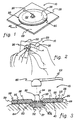
- perforated biomedical electrode 10 constructed in accordance with the principles of the present invention.
- the novel construction of perforated biomedical electrode 10 allows a clinician to readily reduce the contact surface size of perforated biomedical electrode 10 prior to use as shown in FIG. 2.
- perforated biomedical electrode 10 may be used with monitoring devices including cardioscopes, electrocardiographs, and electrocardiograms for monitoring the operation of the heart, with stimulating devices including Transcutaneous Electrical Nerve Stimulation (TENS) or Neuromuscular Stimulation (NMS), as well as with therapeutic devices.
- monitoring devices including cardioscopes, electrocardiographs, and electrocardiograms for monitoring the operation of the heart
- stimulating devices including Transcutaneous Electrical Nerve Stimulation (TENS) or Neuromuscular Stimulation (NMS), as well as with therapeutic devices.
- the perforated biomedical electrode may also be used with defibrillation devices, as well as with electrosurgical instruments.
- illustrated perforated biomedical electrode 10 includes a disk-shaped pad 20 having a top surface 22, a bottom surface 24 (FIG. 3), and a surrounding edge 29 (FIG. 3).
- Pad 20 further includes an inner, disk-shaped portion 26 and an outer, annular, detachable portion 28.
- An electrode 30 is attached to inner portion 26, and a pressure-sensitive adhesive layer 40 is disposed on bottom surface 24 (FIG. 3) of pad 20.
- Pad 20 may include a series of apertures 25 which extends from top surface 22 to bottom surface 24 (FIG. 3) and along which outer detachable portion 28 is separable from pad 20.
- the series of apertures 25 form a predefined detachable means or predefined line of separation between outer detachable portion 28 and inner portion 26 so that first and second portions are sufficiently attached together to act as one, and so that outer detachable portion 28 may be readily and cleanly removed from inner portion 26 along the predefined line of separation by a clinician.
- the series of apertures 25 include a series of elongated slits.
- apertures 25 are illustrated as slits in FIGS. 1-3, from the present description it will be appreciated by those skilled in the art that apertures 25 can include a series of circular holes, elongated openings, or other suitable shaped passageways which allow detachment of a portion of the biomedical electrode.
- the apertures need not extend completely through the pad so long as a portion of the biomedical electrode may be readily detached along the predefined line of separation or break line.
- the pad may have a reduced thickness which defines the line of separation along which the detachable portion is separable from the pad.
- pad 20 may be of any suitable shape, e.g., oval, square, or rectangle.
- the predefined detachable means need not peripherally extend completely around the first or inner portion of the biomedical electrode.
- a perforated biomedical electrode may be provided with a predefined detachable means which extends from one edge portion of the pad to an opposite edge portion of the pad, e.g., a rectangular-shaped pad having one or more readily detachable end portions.
- Pad 20 may be formed from an electrically insulating or non-conductive material which is flexible to conform to a skin surface and/or flex with movement of the patient's skin.
- pad 20 can be formed from a sheet of plastic foam, such as foamed polyurethane, polyethylene, or foam rubber, etc.
- Perforated biomedical electrode 10 may further include a release or protective cover sheet 50 (FIGS. 1 and 2) disposed on adhesive layer 40 for protecting adhesive layer 40.
- Protective cover sheet 50 may be removed or peeled off to expose pressure-sensitive adhesive layer 40 just prior to use.
- the protective cover sheet can comprise a suitable thin, transparent or opaque, plastic material.
- pad 20 may include a pull tab which can be easily grasped by a clinician for removing the protective cover sheet.
- release sheet 50 is removed from perforated biomedical electrode 10 and the biomedical electrode is attached to the skin of a patient by means of pressure-sensitive adhesive layer 40 (FIG. 1), e.g., for use on a patient (FIG. 3).
- a clinician can easily remove outer detachable portion 28 of perforated biomedical electrode 10 prior to removal of protective cover sheet 50, as shown in FIG. 2. Subsequently, protective cover sheet 50 can be removed from the inner portion, and the reduced size biomedical electrode can be attached to the skin of a patient by means of pressure-sensitive adhesive layer 40, e.g., for use on a child or a small adult (FIG. 4).
- outer detachable portion 28 comprises outer circular edge 29, and the series of apertures 25 are concentrically disposed so that the outer detachable portion 28 has a width, e.g., about one-third the distance from outer circular edge 29 to the center of inner portion 26.
- electrode 30 may comprise a generally inverted T-shaped cross-section having a bottom planar member 32 and an upwardly extending electrical projection 34 which extends through a hole in pad 20.
- Electrode 30 may comprise a metal, an electrically conductive plastic, or other suitable electrically conductive materials or combinations thereof. In certain electrode designs, it may be useful to have a collar 35 which operably attaches to electrical projection 34 to retain electrode 30 to pad 20.
- Perforated biomedical electrode 10 can be connected to a monitoring or stimulating device via an electrical connector 60 of an electrical lead wire 62. Desirably, electrical connector 60 is readily and releasably attachable to electrical projection 34 in a snap-fit manner.
- the electrode may have an electrically conductive tab-type connector means which attaches to an alligator clip type termination on the leadwire.
- Other types of connector means depending upon the biomedical electrode configuration, may also employ the perforated biomedical electrode design.
- a porous member 37 may be disposed on the bottom surface of planar member 32 for receiving and absorbing an electrically conductive fluid or jelly, e.g., saline gel, or other equally suitable medium, to provide a conductive path between the electrode and the skin of the patient.
- Perforated biomedical electrode 10 may also comprise an annular ring 23 disposed around porous member 37 to contain the conductive medium.
- Ring 23 may be fabricated from any suitable material, and is desirably formed of the same material as pad 20 and secured to pad 20 with a layer of adhesive therebetween. Desirably, the bottom portion of ring 23 includes an adhesive layer 40a.
- the perforated biomedical electrodes of the present invention can be manufactured and sold with an electrically conductive fluid or jelly absorbed into the porous pad and protected by the protective cover sheet to prevent the electrically conductive fluid or jelly from drying out.
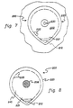
- FIG. 5 illustrates an alternative embodiment of the present invention for a perforated biomedical electrode 100 having a plurality of outer detachable portions 128a and 128b. As shown in FIG. 5, a plurality of perforated biomedical electrodes 100 can be disposed on a single release or protective cover sheet 150.
- illustrated perforated biomedical electrode 100 is desirably suitable for nerve and/or neuromuscular stimulation and includes a bottom surface which provides a ground to transfer electrical impulses to a patient's skin.
- the bottom surface can be readily reduced in size to one of three different sizes depending on the particular application.
- perforated biomedical electrode 100 includes a disk-shaped pad 120 having a top surface 122 and a bottom surface 124.
- An electrically conductive layer 131 is attached to bottom surface 124 of pad 120, and an electrically conductive pressure-sensitive adhesive layer 140 is disposed on the bottom surface of electrically conductive layer 131.
- Pad 120 and electrically conductive layer 131 further comprise a first series of apertures 125a, and a second series of apertures 125b, which extend from top surface 122 of pad 120 to a bottom surface of electrically conductive layer 131.
- first series of apertures 125a and second series of apertures 125b are concentrically aligned.
- the electrically conductive layer may be a flexible metal foil and the electrically conductive pressure-sensitive adhesive layer may include an electrically conductive gel.
- biomedical electrode 100 is provided with three different effective biomedical electrode sizes.
- the area of contact between the biomedical electrode and the patient's skin can be incrementally reduced by removing one or both outer portions, thereby varying the resistance or impedance between the biomedical electrode and the patient's skin.
- FIG. 7 illustrates a perforated teardrop-shaped biomedical electrode 200 placed on a patient's skin surface.
- Biomedical electrode 200 includes a pad 220 having a main portion 222 and a pull tab portion 221.
- a series of apertures 225 extends through portions 221 and 222 of pad 220.
- An electrode 230 may be centered on main portion 222.
- an adhesive 240 may be cast over the bottom surface of biomedical electrode 200 and a conductive jelly 238 may be centered and aligned with electrode 230.
- the bottom surface of tab portion 221 of pad 220 contains a generally triangular-shaped release sheet portion 212 which prevents adhesive 240 on a portion of tab portion 221 from adhering to the patient's skin.
- triangular-shaped release sheet portion 212 may be made by using a back slit die cutting operation during the manufacturing process of biomedical electrode 200 attached to a release sheet.
- Series of apertures 225 may also extend through a portion of triangular-shaped release sheet portion 212.
- pull tab portion 221 allows a clinician to slid a finger or thumb underneath pull tab portion 221, grasp the tab with the thumb and finger and peel the biomedical electrode off of the patient's skin.
Landscapes
- Health & Medical Sciences (AREA)
- Engineering & Computer Science (AREA)
- Biomedical Technology (AREA)
- Nuclear Medicine, Radiotherapy & Molecular Imaging (AREA)
- Radiology & Medical Imaging (AREA)
- Life Sciences & Earth Sciences (AREA)
- Animal Behavior & Ethology (AREA)
- General Health & Medical Sciences (AREA)
- Public Health (AREA)
- Veterinary Medicine (AREA)
- Electrotherapy Devices (AREA)
- Materials For Medical Uses (AREA)
Applications Claiming Priority (3)
| Application Number | Priority Date | Filing Date | Title |
|---|---|---|---|
| US132416 | 1993-10-06 | ||
| US09/132,416 US6240323B1 (en) | 1998-08-11 | 1998-08-11 | Perforated size adjustable biomedical electrode |
| PCT/US1999/017741 WO2000009202A1 (en) | 1998-08-11 | 1999-08-05 | Biomedical electrode with perforation lines |
Publications (2)
| Publication Number | Publication Date |
|---|---|
| EP1104325A1 EP1104325A1 (en) | 2001-06-06 |
| EP1104325B1 true EP1104325B1 (en) | 2003-11-12 |
Family
ID=22453955
Family Applications (1)
| Application Number | Title | Priority Date | Filing Date |
|---|---|---|---|
| EP99939021A Expired - Lifetime EP1104325B1 (en) | 1998-08-11 | 1999-08-05 | Biomedical electrode with perforation lines |
Country Status (6)
| Country | Link |
|---|---|
| US (1) | US6240323B1 (enExample) |
| EP (1) | EP1104325B1 (enExample) |
| JP (1) | JP4155709B2 (enExample) |
| AT (1) | ATE253955T1 (enExample) |
| DE (1) | DE69912802T2 (enExample) |
| WO (1) | WO2000009202A1 (enExample) |
Families Citing this family (83)
| Publication number | Priority date | Publication date | Assignee | Title |
|---|---|---|---|---|
| US6714824B1 (en) * | 2000-05-26 | 2004-03-30 | Koninklijke Philips Electronics N.V. | Universal electrode system and methods of use and manufacture |
| US20060122474A1 (en) | 2000-06-16 | 2006-06-08 | Bodymedia, Inc. | Apparatus for monitoring health, wellness and fitness |
| US7285090B2 (en) * | 2000-06-16 | 2007-10-23 | Bodymedia, Inc. | Apparatus for detecting, receiving, deriving and displaying human physiological and contextual information |
| WO2005029242A2 (en) | 2000-06-16 | 2005-03-31 | Bodymedia, Inc. | System for monitoring and managing body weight and other physiological conditions including iterative and personalized planning, intervention and reporting capability |
| US6551256B1 (en) * | 2000-08-08 | 2003-04-22 | Dymedix Corporation | Snore sensor |
| ES2290797T3 (es) | 2001-06-01 | 2008-02-16 | Covidien Ag | Conector del cable con un almohadilla de retorno. |
| US6796828B2 (en) * | 2001-06-01 | 2004-09-28 | Sherwood Services Ag | Return pad cable connector |
| US7062321B2 (en) * | 2001-09-14 | 2006-06-13 | Koninklijke Philips Electronics, N.V. | Method and apparatus for defibrillating patients of all ages |
| US6782293B2 (en) * | 2001-09-14 | 2004-08-24 | Zoll Medical Corporation | Defibrillation electrode assembly including CPR pad |
| DE20202757U1 (de) * | 2002-02-22 | 2002-08-29 | Tyco Healthcare Deutschland Manufacturing GmbH, 93333 Neustadt | Biomedizinische Elektrode |
| US6799063B2 (en) | 2002-02-27 | 2004-09-28 | Medivance Incorporated | Temperature control pads with integral electrodes |
| US6965799B2 (en) * | 2002-03-08 | 2005-11-15 | Medtronic Physio-Control Manufacturing Corp. | Therapy and monitoring electrodes with patient accommodating features |
| US7020508B2 (en) * | 2002-08-22 | 2006-03-28 | Bodymedia, Inc. | Apparatus for detecting human physiological and contextual information |
| CH695541A5 (fr) * | 2002-08-22 | 2006-06-30 | Compex Medical Sa | Ensemble de fixation pour électrode biomédicale. |
| US20070100666A1 (en) * | 2002-08-22 | 2007-05-03 | Stivoric John M | Devices and systems for contextual and physiological-based detection, monitoring, reporting, entertainment, and control of other devices |
| US6860881B2 (en) | 2002-09-25 | 2005-03-01 | Sherwood Services Ag | Multiple RF return pad contact detection system |
| US7182738B2 (en) | 2003-04-23 | 2007-02-27 | Marctec, Llc | Patient monitoring apparatus and method for orthosis and other devices |
| US20050013957A1 (en) * | 2003-07-15 | 2005-01-20 | Boris Leschinsky | Disposable medical article with multiple adhesives for skin attachment |
| EP1667579A4 (en) | 2003-09-12 | 2008-06-11 | Bodymedia Inc | METHOD AND DEVICE FOR MEASURING CARDIAC PARAMETERS |
| EP1675499B1 (en) * | 2003-10-23 | 2011-10-19 | Covidien AG | Redundant temperature monitoring in electrosurgical systems for safety mitigation |
| CA2560323C (en) * | 2004-03-22 | 2014-01-07 | Bodymedia, Inc. | Non-invasive temperature monitoring device |
| USD519210S1 (en) * | 2004-07-14 | 2006-04-18 | Fernandez Cesar A | Electrode with disposable skin-interfaceable housing |
| DE102004056341A1 (de) * | 2004-11-22 | 2006-05-24 | Weinmann Geräte für Medizin GmbH + Co. KG | Elektrode für Defibrillatoren |
| CA2541037A1 (en) * | 2005-03-31 | 2006-09-30 | Sherwood Services Ag | Temperature regulating patient return electrode and return electrode monitoring system |
| USD566847S1 (en) * | 2005-04-22 | 2008-04-15 | Inovise Medical, Inc. | Electrical sensor conductor pattern |
| US7736359B2 (en) | 2006-01-12 | 2010-06-15 | Covidien Ag | RF return pad current detection system |
| US20070167942A1 (en) * | 2006-01-18 | 2007-07-19 | Sherwood Services Ag | RF return pad current distribution system |
| JP4709672B2 (ja) * | 2006-03-22 | 2011-06-22 | 株式会社メッツ | 心電計用電極 |
| US7616980B2 (en) | 2006-05-08 | 2009-11-10 | Tyco Healthcare Group Lp | Radial electrode array |
| US7637907B2 (en) | 2006-09-19 | 2009-12-29 | Covidien Ag | System and method for return electrode monitoring |
| US8109883B2 (en) * | 2006-09-28 | 2012-02-07 | Tyco Healthcare Group Lp | Cable monitoring apparatus |
| US7927329B2 (en) | 2006-09-28 | 2011-04-19 | Covidien Ag | Temperature sensing return electrode pad |
| US7722603B2 (en) * | 2006-09-28 | 2010-05-25 | Covidien Ag | Smart return electrode pad |
| US8180425B2 (en) | 2006-12-05 | 2012-05-15 | Tyco Healthcare Group Lp | ECG lead wire organizer and dispenser |
| US8668651B2 (en) | 2006-12-05 | 2014-03-11 | Covidien Lp | ECG lead set and ECG adapter system |
| US8238996B2 (en) * | 2006-12-05 | 2012-08-07 | Tyco Healthcare Group Lp | Electrode array |
| US20080319786A1 (en) * | 2007-02-16 | 2008-12-25 | Stivoric John M | Publishing and insurance applications of lifeotypes |
| US8777940B2 (en) * | 2007-04-03 | 2014-07-15 | Covidien Lp | System and method for providing even heat distribution and cooling return pads |
| US20080249524A1 (en) * | 2007-04-03 | 2008-10-09 | Tyco Healthcare Group Lp | System and method for providing even heat distribution and cooling return pads |
| US8021360B2 (en) | 2007-04-03 | 2011-09-20 | Tyco Healthcare Group Lp | System and method for providing even heat distribution and cooling return pads |
| US8080007B2 (en) | 2007-05-07 | 2011-12-20 | Tyco Healthcare Group Lp | Capacitive electrosurgical return pad with contact quality monitoring |
| US8231614B2 (en) * | 2007-05-11 | 2012-07-31 | Tyco Healthcare Group Lp | Temperature monitoring return electrode |
| US8388612B2 (en) | 2007-05-11 | 2013-03-05 | Covidien Lp | Temperature monitoring return electrode |
| US20080312651A1 (en) * | 2007-06-15 | 2008-12-18 | Karl Pope | Apparatus and methods for selective heating of tissue |
| US8801703B2 (en) | 2007-08-01 | 2014-08-12 | Covidien Lp | System and method for return electrode monitoring |
| US8100898B2 (en) | 2007-08-01 | 2012-01-24 | Tyco Healthcare Group Lp | System and method for return electrode monitoring |
| US9757554B2 (en) | 2007-08-23 | 2017-09-12 | Bioness Inc. | System for transmitting electrical current to a bodily tissue |
| DE102007044020A1 (de) * | 2007-09-14 | 2009-04-09 | Dräger Medical AG & Co. KG | Medizinische Elektrode |
| DE102007044019A1 (de) * | 2007-09-14 | 2009-04-09 | Dräger Medical AG & Co. KG | Medizinische Elektrode |
| US20090088652A1 (en) | 2007-09-28 | 2009-04-02 | Kathleen Tremblay | Physiological sensor placement and signal transmission device |
| CA2646037C (en) | 2007-12-11 | 2017-11-28 | Tyco Healthcare Group Lp | Ecg electrode connector |
| US20090171341A1 (en) * | 2007-12-28 | 2009-07-02 | Karl Pope | Dispersive return electrode and methods |
| US8579794B2 (en) * | 2008-05-02 | 2013-11-12 | Dymedix Corporation | Agitator to stimulate the central nervous system |
| US20090306647A1 (en) * | 2008-06-05 | 2009-12-10 | Greg Leyh | Dynamically controllable multi-electrode apparatus & methods |
| US8172835B2 (en) | 2008-06-05 | 2012-05-08 | Cutera, Inc. | Subcutaneous electric field distribution system and methods |
| US20100022999A1 (en) * | 2008-07-24 | 2010-01-28 | Gollnick David A | Symmetrical rf electrosurgical system and methods |
| US20100056855A1 (en) * | 2008-08-22 | 2010-03-04 | Dymedix Corporation | Closed loop neuromodulator |
| WO2010030909A1 (en) * | 2008-09-12 | 2010-03-18 | Dymedix Corporation | Wireless pyro/piezo sensor system |
| USD737979S1 (en) | 2008-12-09 | 2015-09-01 | Covidien Lp | ECG electrode connector |
| US8211097B2 (en) | 2009-02-13 | 2012-07-03 | Cutera, Inc. | Optimizing RF power spatial distribution using frequency control |
| US8694080B2 (en) | 2009-10-21 | 2014-04-08 | Covidien Lp | ECG lead system |
| CA2746944C (en) | 2010-07-29 | 2018-09-25 | Tyco Healthcare Group Lp | Ecg adapter system and method |
| JP5751002B2 (ja) * | 2010-11-17 | 2015-07-22 | オムロンヘルスケア株式会社 | 電極用パッド |
| US8868217B2 (en) * | 2011-06-27 | 2014-10-21 | Bioness Neuromodulation Ltd. | Electrode for muscle stimulation |
| EP2734106B1 (en) | 2011-07-22 | 2019-09-18 | Kpr U.S., Llc | Ecg electrode connector |
| EP2856937B1 (en) * | 2012-05-28 | 2021-08-18 | Nipro Corporation | Electrode pad for use on living organism |
| US11058338B2 (en) | 2012-12-31 | 2021-07-13 | Suunto Oy | Electrode assembly |
| FI124657B (en) * | 2012-12-31 | 2014-11-28 | Suunto Oy | Male connector for telemetric receiver |
| US11944441B2 (en) | 2012-12-31 | 2024-04-02 | Suunto Oy | Electro-mechanic assembly and integrated snap connectors |
| US9408546B2 (en) | 2013-03-15 | 2016-08-09 | Covidien Lp | Radiolucent ECG electrode system |
| USD771818S1 (en) | 2013-03-15 | 2016-11-15 | Covidien Lp | ECG electrode connector |
| ES2726185T3 (es) | 2013-03-15 | 2019-10-02 | Kpr Us Llc | Conector de electrodo con un elemento conductor |
| EP2999437A1 (en) * | 2013-05-23 | 2016-03-30 | Zimmer, Inc. | Heated bolt for modular hip stem |
| JP7036728B2 (ja) | 2016-01-11 | 2022-03-15 | バイオネス インコーポレイテッド | 歩行調整用のシステム及び装置並びにその使用方法 |
| JP6713004B2 (ja) * | 2016-01-14 | 2020-06-24 | テルモ株式会社 | 貼付部材及び医療器具 |
| CA3073215A1 (en) * | 2017-10-06 | 2019-04-11 | Medtronic Xomed, Inc. | Pledget stimulation and recording electrode assemblies |
| TWM565039U (zh) * | 2018-03-14 | 2018-08-11 | 迪伸電子股份有限公司 | 貼片固定式的雷射電療器及雷射發射器 |
| KR102839085B1 (ko) | 2019-01-24 | 2025-07-28 | 오츠카 세이야쿠 가부시키가이샤 | 탄성 웨어러블 센서 |
| SG11202109479XA (en) * | 2019-03-07 | 2021-09-29 | Otsuka Pharma Co Ltd | Methods and apparatus for activation of a wearable patch |
| EP3934734A1 (en) * | 2019-03-07 | 2022-01-12 | Otsuka Pharmaceutical Co., Ltd. | Methods and apparatus for a frame surrounding a wearable patch |
| ES3048209T3 (en) * | 2019-09-27 | 2025-12-09 | Liberate Medical Llc | Devices for adjusting and tracking respiration-stimulating electrodes |
| US11813420B2 (en) | 2020-03-25 | 2023-11-14 | Medtronic Vascular, Inc. | Balloon catheter |
| US20230084585A1 (en) * | 2021-09-14 | 2023-03-16 | Stryker Corporation | Electrode assembly, systems, and methods of use thereof |
Family Cites Families (11)
| Publication number | Priority date | Publication date | Assignee | Title |
|---|---|---|---|---|
| US4233987A (en) * | 1978-08-18 | 1980-11-18 | Alfred Feingold | Curvilinear electrocardiograph electrode strip |
| DE3070796D1 (en) | 1980-01-23 | 1985-08-01 | Minnesota Mining & Mfg | Method of manufacturing a dry biomedical electrode |
| US4834103A (en) | 1980-08-08 | 1989-05-30 | Darox Corporation | Disposable physiological electrode set |
| US4331153A (en) | 1980-11-13 | 1982-05-25 | Healy James W | Disposable EKG electrode |
| US4580339A (en) | 1982-08-05 | 1986-04-08 | Empi, Inc. | Method for fabricating a disposable electrode for transcutaneous nerve stimulator |
| US4640289A (en) * | 1983-11-14 | 1987-02-03 | Minnesota Mining And Manufacturing Company | Biomedical electrode |
| US4674512A (en) | 1986-02-03 | 1987-06-23 | Lectec Corporation | Medical electrode for monitoring and diagnostic use |
| US4757817A (en) | 1987-03-09 | 1988-07-19 | Lead-Lok, Inc. | Adhesive electrode pad |
| US5330527A (en) | 1988-03-25 | 1994-07-19 | Lec Tec Corporation | Multipurpose medical electrode |
| US5348007A (en) | 1993-03-24 | 1994-09-20 | Conmed Corporation | Biomedical electrode |
| US5505201A (en) | 1994-04-20 | 1996-04-09 | Case Western Reserve University | Implantable helical spiral cuff electrode |
-
1998
- 1998-08-11 US US09/132,416 patent/US6240323B1/en not_active Expired - Lifetime
-
1999
- 1999-08-05 DE DE69912802T patent/DE69912802T2/de not_active Expired - Lifetime
- 1999-08-05 EP EP99939021A patent/EP1104325B1/en not_active Expired - Lifetime
- 1999-08-05 AT AT99939021T patent/ATE253955T1/de not_active IP Right Cessation
- 1999-08-05 JP JP2000564703A patent/JP4155709B2/ja not_active Expired - Fee Related
- 1999-08-05 WO PCT/US1999/017741 patent/WO2000009202A1/en not_active Ceased
Also Published As
| Publication number | Publication date |
|---|---|
| EP1104325A1 (en) | 2001-06-06 |
| WO2000009202A1 (en) | 2000-02-24 |
| DE69912802T2 (de) | 2004-08-12 |
| DE69912802D1 (de) | 2003-12-18 |
| JP4155709B2 (ja) | 2008-09-24 |
| ATE253955T1 (de) | 2003-11-15 |
| JP2002522178A (ja) | 2002-07-23 |
| US6240323B1 (en) | 2001-05-29 |
Similar Documents
| Publication | Publication Date | Title |
|---|---|---|
| EP1104325B1 (en) | Biomedical electrode with perforation lines | |
| US5265579A (en) | X-ray transparent monitoring electrode and method for making | |
| US5133356A (en) | Biomedical electrode having centrally-positioned tab construction | |
| US3960141A (en) | Electrosurgical and ECG monitoring system | |
| US6532379B2 (en) | Bio-electic interface adapter with twelve-lead ECG capability and provision for defibrillation | |
| EP1235615B1 (en) | Biomedical electrodes and biomedical electrodes for electrostimulation | |
| US4715382A (en) | Flat biomedical electrode with reuseable lead wire | |
| CA1246682A (en) | Biomedical electrode | |
| US4727881A (en) | Biomedical electrode | |
| US5150708A (en) | Tabbed defibrillator electrode pad | |
| US8868216B2 (en) | Electrode garment | |
| JP2001527432A (ja) | 自己包装式生体用電極 | |
| WO1996000599A1 (en) | Vented electrode | |
| CA1264818A (en) | Multipolar medical electrode | |
| JPH0463689B2 (enExample) | ||
| US5226225A (en) | Method of making a biomedical electrode | |
| US7668604B2 (en) | Packaging for medical pads and electrodes | |
| US7164939B2 (en) | Disposable biomedical electrode having multiple connection sites | |
| CN219539246U (zh) | 一种医用凝胶贴 | |
| WO1998002088A1 (en) | Biomedical electrode | |
| EP4329612B1 (en) | Medical electrode | |
| CN221013287U (zh) | 一种心电监护用电极片 | |
| CA2128831A1 (en) | Monitoring or diagnostic electrode or sensor |
Legal Events
| Date | Code | Title | Description |
|---|---|---|---|
| PUAI | Public reference made under article 153(3) epc to a published international application that has entered the european phase |
Free format text: ORIGINAL CODE: 0009012 |
|
| 17P | Request for examination filed |
Effective date: 20010208 |
|
| AK | Designated contracting states |
Kind code of ref document: A1 Designated state(s): AT BE CH CY DE DK ES FI FR GB GR IE IT LI LU MC NL PT SE |
|
| GRAH | Despatch of communication of intention to grant a patent |
Free format text: ORIGINAL CODE: EPIDOS IGRA |
|
| GRAS | Grant fee paid |
Free format text: ORIGINAL CODE: EPIDOSNIGR3 |
|
| GRAA | (expected) grant |
Free format text: ORIGINAL CODE: 0009210 |
|
| AK | Designated contracting states |
Kind code of ref document: B1 Designated state(s): AT BE CH CY DE DK ES FI FR GB GR IE IT LI LU MC NL PT SE |
|
| PG25 | Lapsed in a contracting state [announced via postgrant information from national office to epo] |
Ref country code: NL Free format text: LAPSE BECAUSE OF FAILURE TO SUBMIT A TRANSLATION OF THE DESCRIPTION OR TO PAY THE FEE WITHIN THE PRESCRIBED TIME-LIMIT Effective date: 20031112 Ref country code: LI Free format text: LAPSE BECAUSE OF FAILURE TO SUBMIT A TRANSLATION OF THE DESCRIPTION OR TO PAY THE FEE WITHIN THE PRESCRIBED TIME-LIMIT Effective date: 20031112 Ref country code: FR Free format text: LAPSE BECAUSE OF FAILURE TO SUBMIT A TRANSLATION OF THE DESCRIPTION OR TO PAY THE FEE WITHIN THE PRESCRIBED TIME-LIMIT Effective date: 20031112 Ref country code: FI Free format text: LAPSE BECAUSE OF FAILURE TO SUBMIT A TRANSLATION OF THE DESCRIPTION OR TO PAY THE FEE WITHIN THE PRESCRIBED TIME-LIMIT Effective date: 20031112 Ref country code: CY Free format text: LAPSE BECAUSE OF FAILURE TO SUBMIT A TRANSLATION OF THE DESCRIPTION OR TO PAY THE FEE WITHIN THE PRESCRIBED TIME-LIMIT Effective date: 20031112 Ref country code: CH Free format text: LAPSE BECAUSE OF FAILURE TO SUBMIT A TRANSLATION OF THE DESCRIPTION OR TO PAY THE FEE WITHIN THE PRESCRIBED TIME-LIMIT Effective date: 20031112 Ref country code: BE Free format text: LAPSE BECAUSE OF FAILURE TO SUBMIT A TRANSLATION OF THE DESCRIPTION OR TO PAY THE FEE WITHIN THE PRESCRIBED TIME-LIMIT Effective date: 20031112 Ref country code: AT Free format text: LAPSE BECAUSE OF FAILURE TO SUBMIT A TRANSLATION OF THE DESCRIPTION OR TO PAY THE FEE WITHIN THE PRESCRIBED TIME-LIMIT Effective date: 20031112 |
|
| REG | Reference to a national code |
Ref country code: GB Ref legal event code: FG4D |
|
| REG | Reference to a national code |
Ref country code: CH Ref legal event code: EP |
|
| REF | Corresponds to: |
Ref document number: 69912802 Country of ref document: DE Date of ref document: 20031218 Kind code of ref document: P |
|
| REG | Reference to a national code |
Ref country code: IE Ref legal event code: FG4D |
|
| PG25 | Lapsed in a contracting state [announced via postgrant information from national office to epo] |
Ref country code: SE Free format text: LAPSE BECAUSE OF FAILURE TO SUBMIT A TRANSLATION OF THE DESCRIPTION OR TO PAY THE FEE WITHIN THE PRESCRIBED TIME-LIMIT Effective date: 20040212 Ref country code: GR Free format text: LAPSE BECAUSE OF FAILURE TO SUBMIT A TRANSLATION OF THE DESCRIPTION OR TO PAY THE FEE WITHIN THE PRESCRIBED TIME-LIMIT Effective date: 20040212 Ref country code: DK Free format text: LAPSE BECAUSE OF FAILURE TO SUBMIT A TRANSLATION OF THE DESCRIPTION OR TO PAY THE FEE WITHIN THE PRESCRIBED TIME-LIMIT Effective date: 20040212 |
|
| PG25 | Lapsed in a contracting state [announced via postgrant information from national office to epo] |
Ref country code: ES Free format text: LAPSE BECAUSE OF FAILURE TO SUBMIT A TRANSLATION OF THE DESCRIPTION OR TO PAY THE FEE WITHIN THE PRESCRIBED TIME-LIMIT Effective date: 20040223 |
|
| NLV1 | Nl: lapsed or annulled due to failure to fulfill the requirements of art. 29p and 29m of the patents act | ||
| REG | Reference to a national code |
Ref country code: CH Ref legal event code: PL |
|
| PGFP | Annual fee paid to national office [announced via postgrant information from national office to epo] |
Ref country code: FR Payment date: 20040804 Year of fee payment: 6 |
|
| PLBE | No opposition filed within time limit |
Free format text: ORIGINAL CODE: 0009261 |
|
| STAA | Information on the status of an ep patent application or granted ep patent |
Free format text: STATUS: NO OPPOSITION FILED WITHIN TIME LIMIT |
|
| 26N | No opposition filed |
Effective date: 20040813 |
|
| EN | Fr: translation not filed | ||
| PGFP | Annual fee paid to national office [announced via postgrant information from national office to epo] |
Ref country code: LU Payment date: 20070705 Year of fee payment: 9 |
|
| PG25 | Lapsed in a contracting state [announced via postgrant information from national office to epo] |
Ref country code: PT Free format text: LAPSE BECAUSE OF NON-PAYMENT OF DUE FEES Effective date: 20040412 |
|
| PG25 | Lapsed in a contracting state [announced via postgrant information from national office to epo] |
Ref country code: LU Free format text: LAPSE BECAUSE OF NON-PAYMENT OF DUE FEES Effective date: 20080805 |
|
| PGFP | Annual fee paid to national office [announced via postgrant information from national office to epo] |
Ref country code: MC Payment date: 20100720 Year of fee payment: 12 Ref country code: IE Payment date: 20100709 Year of fee payment: 12 |
|
| PG25 | Lapsed in a contracting state [announced via postgrant information from national office to epo] |
Ref country code: MC Free format text: LAPSE BECAUSE OF NON-PAYMENT OF DUE FEES Effective date: 20110831 |
|
| REG | Reference to a national code |
Ref country code: IE Ref legal event code: MM4A |
|
| PG25 | Lapsed in a contracting state [announced via postgrant information from national office to epo] |
Ref country code: IE Free format text: LAPSE BECAUSE OF NON-PAYMENT OF DUE FEES Effective date: 20110805 |
|
| REG | Reference to a national code |
Ref country code: DE Ref legal event code: R082 Ref document number: 69912802 Country of ref document: DE Representative=s name: MAI, OPPERMANN & PARTNER I. L., DE |
|
| PGFP | Annual fee paid to national office [announced via postgrant information from national office to epo] |
Ref country code: DE Payment date: 20150831 Year of fee payment: 17 Ref country code: GB Payment date: 20150728 Year of fee payment: 17 |
|
| PGFP | Annual fee paid to national office [announced via postgrant information from national office to epo] |
Ref country code: IT Payment date: 20150817 Year of fee payment: 17 |
|
| REG | Reference to a national code |
Ref country code: DE Ref legal event code: R119 Ref document number: 69912802 Country of ref document: DE |
|
| GBPC | Gb: european patent ceased through non-payment of renewal fee |
Effective date: 20160805 |
|
| PG25 | Lapsed in a contracting state [announced via postgrant information from national office to epo] |
Ref country code: GB Free format text: LAPSE BECAUSE OF NON-PAYMENT OF DUE FEES Effective date: 20160805 Ref country code: DE Free format text: LAPSE BECAUSE OF NON-PAYMENT OF DUE FEES Effective date: 20170301 |
|
| PG25 | Lapsed in a contracting state [announced via postgrant information from national office to epo] |
Ref country code: IT Free format text: LAPSE BECAUSE OF NON-PAYMENT OF DUE FEES Effective date: 20160805 |