EP1104253B1 - Joint indexe pour autocuiseur, et autocuiseur equipe d'un tel joint - Google Patents
Joint indexe pour autocuiseur, et autocuiseur equipe d'un tel joint Download PDFInfo
- Publication number
- EP1104253B1 EP1104253B1 EP99936730A EP99936730A EP1104253B1 EP 1104253 B1 EP1104253 B1 EP 1104253B1 EP 99936730 A EP99936730 A EP 99936730A EP 99936730 A EP99936730 A EP 99936730A EP 1104253 B1 EP1104253 B1 EP 1104253B1
- Authority
- EP
- European Patent Office
- Prior art keywords
- seal
- lid
- pressure cooker
- heel
- cover
- Prior art date
- Legal status (The legal status is an assumption and is not a legal conclusion. Google has not performed a legal analysis and makes no representation as to the accuracy of the status listed.)
- Expired - Lifetime
Links
Images


Classifications
-
- A—HUMAN NECESSITIES
- A47—FURNITURE; DOMESTIC ARTICLES OR APPLIANCES; COFFEE MILLS; SPICE MILLS; SUCTION CLEANERS IN GENERAL
- A47J—KITCHEN EQUIPMENT; COFFEE MILLS; SPICE MILLS; APPARATUS FOR MAKING BEVERAGES
- A47J27/00—Cooking-vessels
- A47J27/08—Pressure-cookers; Lids or locking devices specially adapted therefor
- A47J27/09—Safety devices
Definitions
- the invention relates to the field of pressure cookers comprising a tank and a cover provided with a seal intended to ensure the seal between the lid and the pan when the pressure cooker is turned on pressure.
- the present invention relates to an indexing security seal intended for be mounted in the lid of a pressure cooker to ensure sealing pressure between the lid and the pressure cooker pan, as well as a pressure cooker whose cover is suitable for receiving a safety seal at indexing.
- the sudden leakage of fluid to the outside and down the device can result in one hand possibly turn off the heating element with consequences negative side effects in terms of security, and on the other hand to risk suddenly projecting outwards, and possibly towards the user, a fluid burning under pressure.
- such a security device requires multiply the number of notches / notches on the periphery of the joint to ensure the presence of at least one operational notch / notch when the seal is in place between the ramps of the tank and the cover. Indeed, the presence of the ramps of the tank opposes the displacement of the lips of the joint down on some circular areas.
- the seal is provided on its periphery with two radial tabs intended to be inserted into an opening in the edge lateral device of the lid to index the rotation of the joint with that of the cover.
- the seal has a notch on its internal periphery in geometric association with the indexing notches to ensure the extrusion of the seal through the opening.
- Such a safety device nevertheless has the drawback of requiring making an extrusion opening in the cover.
- the disadvantages previously mentioned about extrusion remain, namely a sudden leakage of fluid downwards in the event of overpressure.
- a standard seal not specifically provided to be suitable for such a pressure cooker, that is to say devoid of notches indexing.
- Such a mounting alternative can obviously be considered a potential source of malfunction of the device and generally affects its safety in use.
- the objects assigned to the invention therefore aim to remedy the various drawbacks of the prior art mentioned above and to offer a new indexing safety seal for pressure cookers improving the overall safety of the pressure cooker while being particularly simple design and implementation.
- Another object of the invention is to propose a new security seal to indexing for pressure cooker allowing a joint and particularly simple pressure cooker cover, as well as easy place of the joint.
- Another object of the invention is to propose a safety pressure cooker reinforced and whose design is simplified.
- a safety seal at indexing intended to be mounted in the lid of a pressure cooker in view sealing the pressure between the cover and the tank the pressure cooker, said seal comprising a relative fixing means between the seal and the cover to index the rotation of the seal with that of the cover, characterized in that it comprises at least one notch external to its periphery, to allow in case of internal overpressure in the pressure cooker, a radial deformation of the seal at the level of the external notch.
- a pressure cooker comprising a bowl and a cover for receiving a gasket indexing security.
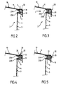
- Figures 1 to 7 illustrate a safety device according to the invention comprising in association an indexing security seal 1 as well as a pressure cooker 2.
- FIGS. 1 to 7 show a pressure cooker of the conventional bayonet type, produced by stamping from a metallic material and comprising a tank 3, for example substantially circular including a bottom (not shown in the figures) and side walls 4.
- the pressure cooker 2 is of the bayonet type and has for this purpose an upper rim 6 extending, in an external radial direction, the upper part of the side wall 4.
- the upper rim 6 is provided on its circumference of a set of ramps 7 (Figure 1) distributed so regular at the periphery of the upper edge 6.
- the ramps 7 are intended to form the bayonet locking system with a series of counter ramps formed in the cover 10 of the pressure cooker.
- the cover 10 is intended to serve, in its peripheral external part, to mounting seat for seal 1 as shown in Figures 1 to 7.
- the cover 10 conventionally comprises a fallen peripheral edge 12 extending the upper face 11 of the cover.
- the seal 1 is in the form of an annular seal produced in a deformable elastomeric material, such as silicone.
- Seal 1 includes in a conventional manner, a heel 21 (FIGS. 4 and 5) forming the central part of the joint 1, the peripheral external face of which forms a front edge 22 intended for come to rest against the internal face, or only a part, of the fallen edge 12.
- the joint 1 comprises from the heel 21 and in the direction opposite to the front edge 22, two end lips, 23A, 23B, respectively forming an upper and lower lip.
- the security seal 1 is indexed and comprises at least an external notch 25 ( Figures 1 and 6) formed at the periphery of the seal 1 in the mass of the heel 21 and from the front edge 22.
- the external notch 25 is in the form of a regular curved cut extending substantially over the entire height of the seal 1, that is to say of the front edge 22 and whose concavity is turned towards the outside of the joint.
- regular concave cutting other shapes are obviously possible, for example in U, V, W ..., without leaving the part of the invention.
- the indexing security seal 1 may include at its periphery several notches 25 external distributed at regular intervals or not at the periphery of the seal.
- the preferred variant of the invention comprises only one and single notch 25.
- the function of the external notch 25 is to allow case of internal overpressure in the pressure cooker 2, a radial deformation of the seal located precisely at the notch 25 to allow the front edge 22 located in the external notch 25 to come, by deformation, to the contact of the internal face of the fallen edge 12 ( Figures 6 and 7).
- the indexing of the safety seal 1 is obtained using a relative fixing means 30 between the seal 1 and the cover 10 for indexing the rotation of the seal 1 with that of the cover 10.
- the seal 1 of indexing security according to the invention is implemented in the cover 10 in a single position, and any rotation of the cover 10 also implies a rotation of seal 1 by the same amount angular relative to the tank 3.
- the fixing means 30, as shown in the Figures 2 to 5, includes a male element and a female element intended for cooperate with one another in order to achieve the relative fixing of the seal 1 and the cover 10.
- the male element is supported or integral with the cover 10, and is for example formed by a prominence 31, such as an axis or a lug, preferably crimped in said cover.
- the female element is arranged in the body of the seal 1, the male element being intended to penetrate into the female element.
- the element female is formed by an orifice 32, crossing or not, formed in the heel 21 of seal 1.
- the prominence 31 is integral with the upper face 11 of cover 10 and extends from its internal face, to proximity of the fallen edge 12, substantially parallel to the latter and substantially vertically in consideration of the figure.
- the prominence 31 is preferably metallic and also preferably attached to the cover 10 by crimping.
- the orifice 32 (FIG. 1) is formed in the heel 21 along an axis substantially perpendicular to the plane extension of the seal 1 so that the protrusion 31 can penetrate into said orifice 32 when the seal 1 is placed in the cover 10 such that is shown in Figure 2.
- the variant embodiment illustrated in FIG. 3 does not differ from that shown in Figure 2 only by the geometrically different orientation of the means of fixation.
- the orientation is radial, the prominence 31 being integral with the internal face of the fallen edge 12 and extending radially from the latter towards the center of the pressure cooker 2.
- the orifice 32 is formed in the heel 21 of the seal 1 from its front edge 22 along a substantially radial axis directed towards the lips 23A and 23B and towards the center of pressure cooker 2.
- the male element is no longer made from the cover 10, but from the body of the joint 1 and preferably comes from the body of the heel 21 itself.
- the variant embodiment illustrated in FIG. 4 shows an element male formed by a lug 35 from the body of the heel 21 and extending from preferably from its upper face towards the cover 10.
- the lug 35 extends from the central part of the heel 21 in a direction substantially normal to the mean plane of extension of the cover 10, said lug being intended to enter an opening 32 formed through the upper face 11 of the cover 10.
- the position of the orifice 32 is made so that the seal 1 is put in place in the cover 10 by insertion of the lug 35 in the opening 32, the seal 1 can perform its priority sealing function between the cover 10 and the tank 2, regardless of the variant considered.
- the variant embodiment illustrated in FIG. 5 does not differ from that illustrated in Figure 4 only by the radial direction of the lug 35 and the orifice 32 relative to the center of the pressure cooker 2 and / or to its axis of symmetry main.
- the lug 35 comes from the body of the heel 21 and extends radially from its front edge 22, the orifice 32 being formed conjugately from the fallen edge 12.
- the seal 1 being placed in position in the cover by relative insertion of the male element 30 into the female element 32, and the cover 10 relatively closed hermetically on the tank 3, the pressure build-up of the device can s 'carry out.
- the seal 1 is subjected to a radial pressure f (see FIGS. 3, 6 and 7) so that the face of the external notch 25 is brought into contact with the fallen edge 12.
- the lower lip 23B is gradually made to move radially in the direction of the force f .
- the lower lip 23B passes over the end edge of the rim 6 and escapes above said edge downwards inducing a progressive leakage of the fluid downwards.
- the escapement of the lower lip 23B can be advantageously promoted and adjusted by punctually reducing the length of the rim 6, by simple trimming of said tank edge to an angular position located in line with the position of the external notch. 25.
- the invention therefore makes it possible to mount a specific joint profile to a cover preventing the fitting of a standard seal in the cover in reason for the presence of the relative fixing means 30 between the seal and the lid.
- the safety aspects of the pressure cooker are thus reinforced since only a seal perfectly suited to the pressure cooker considered can be set up in the pressure cooker and operate with maximum efficiency.
- the design of the seal 1 of the invention is considerably simplified since it only advantageously requires the production an external notch 25 and an orifice 32 or a lug 35.
- the joint will be provided with two notches 25, or even of a series of five external notches 25, as shown in FIG. 8.
- the external notches 25 are evenly distributed at the periphery of the joint 1 and each associated with a pair of notches internal 26 formed in each lip 23A, 23B at the right and in the center of each external notch 25.
- Such an embodiment improves the security of operation of the possible deformation of the joint 1.
- the realization an indexed seal according to the invention makes it possible to control and locate perfectly the leakage area in the pressure cooker since the position of the seal is perfectly known and repetitive. In total, the safety and security aspects simplicity of design are thus greatly improved.
- the cover 10 is provided a creep hole 40 ( Figures 1, 6 and 7) formed through its upper face 11.
- the hole 40 is made in the cover 10 so that when the seal 1 is put in place and indexed relative to the cover 10, the hole 40 is substantially in line with the external notch 25, and preferably centered relative to its axis of curvature.
- the radial displacement of the seal 1 allows the upper lip 23A to release gradually opening 40 ( Figures 6 and 7) to allow a leak gradual upward air movement in the centrifugal radial movement of the seal gradually discovering the creep hole 40.
- the area of realization of the relative fixing means 30 between the joint and the cover can be made in any of the angular positions pressure cooker 2.
- the invention finds its industrial application in the manufacture of seals for domestic pressure cooking and especially for pressure cookers.
Description
- la figure 1 montre, selon une vue de dessus partielle, un exemple de réalisation d'un joint de sécurité conforme à l'invention.
- la figure 2 montre, selon une coupe transversale partielle, une première variante de réalisation du montage d'un joint conforme à l'invention dans le couvercle d'un autocuiseur.
- la figure 3 montre, selon une vue en coupe transversale partielle, une seconde variante de réalisation du montage d'un joint de sécurité conforme à l'invention dans le couvercle d'un autocuiseur.
- la figure 4 montre, selon une vue en coupe transversale partielle, un troisième exemple de réalisation du montage d'un joint de sécurité conforme à l'invention dans le couvercle d'un autocuiseur.
- la figure 5 montre, selon une vue en coupe transversale partielle, une quatrième variante de réalisation du montage d'un joint de sécurité conforme à l'invention dans un couvercle d'autocuiseur.
- la figure 6 montre, selon une vue en coupe transversale partielle prise le long de la ligne VI-VI de la figure 1, un joint de sécurité conforme à l'invention en position de repos.
- la figure 7 montre, selon une vue en coupe transversale partielle identique à celle de la figure 6, un joint conforme à l'invention en position active de dégagement lors d'une surpression.
- la figure 8 montre, selon une vue de dessus, une variante de réalisation d'un joint conforme à l'invention installé sur un autocuiseur en position de verrouillage du couvercle.
Claims (13)
- Joint (1) de sécurité à indexation destiné à être monté dans le couvercle (10) d'un autocuiseur (2) en vue d'assurer l'étanchéité à la pression entre le couvercle (10) et la cuve (3) de l'autocuiseur, caractérisé en ce qu'il comporte au moins une encoche externe (25) à sa périphérie, pour permettre en cas de surpression interne dans l'autocuiseur, une déformation radiale du joint au niveau de l'encoche externe (25).
- Joint selon la revendication 1 caractérisé en ce que chaque encoche externe (25) se présente sous la forme d'une découpe régulière courbe, s'étendant sensiblement sur toute la hauteur du joint (1).
- Joint selon les revendications 1 ou 2 caractérisé en ce qu'il comporte au moins deux encoches externes (25), et de préférence cinq encoches externes (25) réparties de manière régulière à la périphérie du joint (1).
- Couvercle comportant un joint selon l'une des revendications 1 à 3 avec un moyen de fixation (30) relatif entre le joint (1) et le couvercle (10) pour indexer la rotation du joint (1) avec celle du couvercle (10), caractérisé en ce que le moyen de fixation (30) comprend un élément mâle (31, 35) et un élément femelle (32) destinés à coopérer entre eux.
- Couvercle selon la revendication 4 caractérisé en ce que l'élément mâle (31) est supporté par le couvercle (10), l'élément femelle (32) étant ménagé dans le joint (1).
- Couvercle selon la revendication 5 caractérisé en ce que l'élément mâle est formé par une proéminence (31), de préférence sertie dans le couvercle (10), destinée à pénétrer dans l'élément femelle, formé par un orifice (32) ménagé dans le talon (21) du joint (1).
- Couvercle selon la revendication 6 caractérisé en ce que la proéminence (31) est solidaire de la face supérieure (11) du couvercle (10), l'orifice (32) étant ménagé dans le talon (21) du joint (1), selon une direction sensiblement perpendiculaire au plan d'extension du joint (1).
- Couvercle selon la revendication 7 caractérisé en ce que la proéminence (31) est solidaire du bord tombé (12) périphérique du couvercle (10), l'orifice (32) étant ménagé dans le talon (21) du joint (1) selon une direction sensiblement radiale.
- Couvercle selon la revendication 4 caractérisé en ce que l'élément mâle (35) est supporté par le joint (1), et de préférence est une partie intégrante du joint (1), l'élément femelle étant une ouverture (32) ménagée à travers le couvercle (10).
- Couvercle selon la revendication 9 caractérisé en ce que l'élément mâle est formé par un ergot (35) issu du corps même du talon (21) du joint (1), de préférence à sa partie supérieure, ledit ergot étant destiné à pénétrer dans l'ouverture (32) ménagée à travers la face supérieure (12) du couvercle (10).
- Couvercle selon la revendication 9 caractérisé en ce que l'élément mâle est formé par un ergot (35) issu du corps même du talon (21) du joint (1) et s'étendant radialement à partir du rebord frontal (22) du talon (21), ledit ergot étant destiné à pénétrer dans l'ouverture (32) ménagée à travers le bord tombé (12) périphérique du couvercle (10).
- Autocuiseur de préférence à baïonnettes comportant une cuve (3) et un couvercle (10) selon l'une des revendications 4 à 11, ledit couvercle étant pourvu d'un joint (1) de sécurité à indexation conforme à l'une des revendications 1 à 3.
- Autocuiseur selon la revendication 12 caractérisé en ce qu'il comporte un couvercle (10) pourvu d'un trou de fluage (40) ménagé dans sa face supérieure (11), pour permettre une fuite progressive de l'air vers le haut, lors du déplacement radial centrifuge du joint (1) découvrant progressivement le trou de fluage (40).
Applications Claiming Priority (3)
| Application Number | Priority Date | Filing Date | Title |
|---|---|---|---|
| FR9810481 | 1998-08-13 | ||
| FR9810481A FR2782257B1 (fr) | 1998-08-13 | 1998-08-13 | Joint indexe pour autocuiseur, et autocuiseur equipe d'un tel joint |
| PCT/FR1999/001980 WO2000008984A1 (fr) | 1998-08-13 | 1999-08-12 | Joint indexe pour autocuiseur, et autocuiseur equipe d'un tel joint |
Publications (2)
| Publication Number | Publication Date |
|---|---|
| EP1104253A1 EP1104253A1 (fr) | 2001-06-06 |
| EP1104253B1 true EP1104253B1 (fr) | 2003-10-29 |
Family
ID=9529726
Family Applications (1)
| Application Number | Title | Priority Date | Filing Date |
|---|---|---|---|
| EP99936730A Expired - Lifetime EP1104253B1 (fr) | 1998-08-13 | 1999-08-12 | Joint indexe pour autocuiseur, et autocuiseur equipe d'un tel joint |
Country Status (15)
| Country | Link |
|---|---|
| US (1) | US6695319B1 (fr) |
| EP (1) | EP1104253B1 (fr) |
| JP (1) | JP2002522140A (fr) |
| KR (1) | KR20010072476A (fr) |
| CN (1) | CN1143647C (fr) |
| AT (1) | ATE252863T1 (fr) |
| AU (1) | AU5172299A (fr) |
| BR (1) | BR9912993A (fr) |
| CA (1) | CA2340023A1 (fr) |
| DE (1) | DE69912437T2 (fr) |
| EG (1) | EG22234A (fr) |
| ES (1) | ES2211132T3 (fr) |
| FR (1) | FR2782257B1 (fr) |
| TR (1) | TR200100477T2 (fr) |
| WO (1) | WO2000008984A1 (fr) |
Families Citing this family (47)
| Publication number | Priority date | Publication date | Assignee | Title |
|---|---|---|---|---|
| GB0018764D0 (en) * | 2000-07-31 | 2000-09-20 | Wabco Automotive Uk | Pressure relief device |
| FR2874805B1 (fr) * | 2004-09-09 | 2008-05-23 | Seb Sa | Appareil de cuisson sous pression a decompression optimisee |
| DE102005032893B4 (de) * | 2005-07-14 | 2015-05-07 | Ab Skf | Dichtungsanordnung |
| EP1776877A1 (fr) | 2005-10-21 | 2007-04-25 | N.V. Nutricia | Méthode de stimulation de la flore intestinale |
| DE202007001793U1 (de) * | 2007-02-02 | 2008-06-05 | Synkrona Ag | Gargefäß sowie Deckel und Dichtung für ein Gargefäß |
| DE102008030077A1 (de) | 2008-06-25 | 2009-12-31 | Fissler Gmbh | Druckbehälter |
| FR2940389B1 (fr) * | 2008-12-24 | 2015-05-22 | Seb Sa | Joint pour appareil de cuisson d'aliments et appareil pourvu d'un tel joint |
| US10231291B2 (en) * | 2009-02-11 | 2019-03-12 | Jong Hyun Kim | Heating cooker with safety device for microwave oven |
| US9296467B1 (en) * | 2009-06-09 | 2016-03-29 | The Boeing Company | Pressure test door for use with a fuel tank |
| EP2516898B1 (fr) * | 2009-12-23 | 2019-03-06 | Seb S.A. | Joint pour autocuiseur comportant une jupe souple pourvue d'encoches |
| FR2955166B1 (fr) * | 2010-01-11 | 2012-03-30 | Seb Sa | Joint a affaissement vertical, et autocuiseur pourvu d'un tel joint |
| DE102011007809A1 (de) * | 2010-07-28 | 2012-02-02 | Zenker Backformen Gmbh & Co. Kg | Springform |
| US8827637B2 (en) | 2012-03-23 | 2014-09-09 | Pratt & Whitney Canada Corp. | Seal arrangement for gas turbine engines |
| WO2014026045A2 (fr) | 2012-08-08 | 2014-02-13 | Henny Penny Corporation | Joints à lèvre pour appareil de cuisson et appareil de cuisson doté d'un joint à lèvre |
| ES2534609B1 (es) * | 2013-08-07 | 2015-12-29 | Meler Aplicadores De Hot-Melt, S.A. | Equipo fusor |
| FR3019022B1 (fr) | 2014-03-26 | 2017-02-24 | Seb Sa | Appareil de cuisson d'aliments sous pression a baionnettes inversees et methode de fabrication afferente |
| CN107111076B (zh) | 2014-11-26 | 2020-02-28 | 康宁光电通信有限责任公司 | 利用强度构件保持的光纤连接器和子组件 |
| US20160159565A1 (en) * | 2014-12-05 | 2016-06-09 | Den Hartog Industries, Inc. | Double wall liquid storage tank with sealing gasket and compression fitting |
| FR3033993B1 (fr) | 2015-03-26 | 2017-04-28 | Seb Sa | Autocuiseur a baionnette et procede de fabrication afferent |
| FR3036936B1 (fr) | 2015-06-02 | 2019-11-08 | Seb S.A. | Autocuiseur a baionnette pourvu d'une poignee de cuve |
| FR3036934B1 (fr) | 2015-06-02 | 2017-07-14 | Seb Sa | Autocuiseur pourvu d'un organe de commande manuel du verrouillage |
| US10028610B1 (en) * | 2015-12-11 | 2018-07-24 | Jason Sundberg | Whistling pot and pan lid |
| EP3393313B1 (fr) * | 2015-12-23 | 2019-07-31 | Koninklijke Philips N.V. | Ensemble chauffant destiné à être utilisé dans un appareil ménager |
| CN105380530B (zh) * | 2015-12-23 | 2018-12-07 | 珠海格力电器股份有限公司 | 压力锅的锅盖组件及具有其的烹饪器具 |
| CN107126084B (zh) * | 2016-02-29 | 2019-09-17 | 佛山市顺德区美的电热电器制造有限公司 | 锅盖及烹饪器具 |
| CN105708312A (zh) * | 2016-03-18 | 2016-06-29 | 珠海格力电器股份有限公司 | 锅盖组件、具有其的压力锅及压力锅密封圈的固定方法 |
| JP6538603B2 (ja) * | 2016-03-25 | 2019-07-03 | 象印マホービン株式会社 | 加熱調理器 |
| FR3049841B1 (fr) | 2016-04-08 | 2018-04-06 | Seb S.A. | Autocuiseur a securite amelioree |
| US20180086536A1 (en) * | 2016-09-23 | 2018-03-29 | Michel Cabiran | Ring to Space Plates In Microwave Oven |
| CN112716274A (zh) | 2017-08-09 | 2021-04-30 | 沙克忍者运营有限责任公司 | 烹饪系统 |
| FR3072553B1 (fr) * | 2017-10-24 | 2019-09-27 | Seb S.A. | Autocuiseur a fenetre d'extrusion |
| JP2019173993A (ja) * | 2018-03-27 | 2019-10-10 | 三菱電機株式会社 | オーブントースター |
| USD914436S1 (en) | 2018-06-19 | 2021-03-30 | Sharkninja Operating Llc | Air diffuser with food preparation pot |
| USD903413S1 (en) | 2018-08-09 | 2020-12-01 | Sharkninja Operating Llc | Cooking basket |
| USD934027S1 (en) | 2018-08-09 | 2021-10-26 | Sharkninja Operating Llc | Reversible cooking rack |
| USD883014S1 (en) | 2018-08-09 | 2020-05-05 | Sharkninja Operating Llc | Food preparation device |
| USD883015S1 (en) | 2018-08-09 | 2020-05-05 | Sharkninja Operating Llc | Food preparation device and parts thereof |
| US11051654B2 (en) | 2019-02-25 | 2021-07-06 | Sharkninja Operating Llc | Cooking device and components thereof |
| US11751710B2 (en) | 2019-02-25 | 2023-09-12 | Sharkninja Operating Llc | Guard for cooking system |
| TR201906998A2 (tr) * | 2019-05-09 | 2019-06-21 | Alpin Celik Mutfak Gerecleri Sanayi Ve Ticaret Anonim Sirketi | Basinçli kaplar i̇çi̇n bi̇r conta |
| USD918654S1 (en) | 2019-06-06 | 2021-05-11 | Sharkninja Operating Llc | Grill plate |
| USD982375S1 (en) | 2019-06-06 | 2023-04-04 | Sharkninja Operating Llc | Food preparation device |
| GB2588168B (en) * | 2019-10-11 | 2022-12-07 | Yu Cook Holdings Ltd | Cooking vessel for concurrently steaming and poaching food |
| US11647861B2 (en) | 2020-03-30 | 2023-05-16 | Sharkninja Operating Llc | Cooking device and components thereof |
| USD976640S1 (en) * | 2020-07-27 | 2023-01-31 | Sara Elizabeth Bauer | Electric pressure cooker rim cover |
| US11596258B2 (en) * | 2020-11-24 | 2023-03-07 | Capri Scales | Leak resistant cooking pan |
| WO2023106527A1 (fr) * | 2021-12-06 | 2023-06-15 | 주식회사 쿠첸 | Ensemble couvercle d'appareil de cuisson |
Family Cites Families (11)
| Publication number | Priority date | Publication date | Assignee | Title |
|---|---|---|---|---|
| DE1042205B (de) * | 1951-01-15 | 1958-10-30 | Max Keller | Druckkocher |
| DE1076922B (de) * | 1956-02-22 | 1960-03-03 | Rudolf Fissler K G | Sicherungsvorrichtung fuer Dampfkochtoepfe mit am Topfrand nach aussen und am Deckelrand nach innen vorstehenden Randsegmenten |
| ZA776487B (en) * | 1977-04-29 | 1978-08-30 | Nat Presto Ind | Pressure cooker |
| BR5701390U (pt) * | 1977-11-04 | 1979-06-19 | M Chiodo | Aperfeicoamento em panela de pressao |
| DE2801173C2 (de) * | 1978-01-12 | 1984-04-12 | Fissler Gmbh, 6580 Idar-Oberstein | Dampfdruckkochtopf mit seitlich aufschiebbarem Deckel |
| BR8305177A (pt) | 1983-09-22 | 1985-04-30 | Alcan Brasil | Aperfeicoamento em panela de pressao |
| FR2585230B1 (fr) * | 1985-07-26 | 1988-07-22 | Seb Sa | Autocuiseur a dispositif de securite a fuite controlee du joint d'etancheite |
| DE3618231A1 (de) * | 1986-05-30 | 1987-12-03 | Silit Werke | Schnellkochtopf |
| DE4133524C2 (de) * | 1991-10-10 | 1996-08-29 | Fissler Gmbh | Dampfdruckkochtopf |
| ES2078205T1 (es) * | 1994-03-11 | 1995-12-16 | Fissler Gmbh | Olla de vapor a presion y junta de estanqueidad asi como combinacion de junta de estanqueidad/junta deslizante para aquella. |
| FR2720465B1 (fr) * | 1994-05-27 | 1996-07-26 | Seb Sa | Dispositif de sécurité pour récipient sous pression comportant un joint d'étanchéité à section affaiblie. |
-
1998
- 1998-08-13 FR FR9810481A patent/FR2782257B1/fr not_active Expired - Fee Related
-
1999
- 1999-08-12 EG EG100399A patent/EG22234A/xx active
- 1999-08-12 KR KR1020017001897A patent/KR20010072476A/ko not_active Application Discontinuation
- 1999-08-12 CN CNB998094625A patent/CN1143647C/zh not_active Expired - Lifetime
- 1999-08-12 JP JP2000564492A patent/JP2002522140A/ja active Pending
- 1999-08-12 DE DE69912437T patent/DE69912437T2/de not_active Expired - Lifetime
- 1999-08-12 BR BR9912993-0A patent/BR9912993A/pt not_active Application Discontinuation
- 1999-08-12 WO PCT/FR1999/001980 patent/WO2000008984A1/fr not_active Application Discontinuation
- 1999-08-12 AT AT99936730T patent/ATE252863T1/de not_active IP Right Cessation
- 1999-08-12 US US09/762,669 patent/US6695319B1/en not_active Expired - Fee Related
- 1999-08-12 TR TR2001/00477T patent/TR200100477T2/xx unknown
- 1999-08-12 CA CA002340023A patent/CA2340023A1/fr not_active Abandoned
- 1999-08-12 ES ES99936730T patent/ES2211132T3/es not_active Expired - Lifetime
- 1999-08-12 AU AU51722/99A patent/AU5172299A/en not_active Abandoned
- 1999-08-12 EP EP99936730A patent/EP1104253B1/fr not_active Expired - Lifetime
Also Published As
| Publication number | Publication date |
|---|---|
| AU5172299A (en) | 2000-03-06 |
| ATE252863T1 (de) | 2003-11-15 |
| US6695319B1 (en) | 2004-02-24 |
| DE69912437D1 (de) | 2003-12-04 |
| BR9912993A (pt) | 2001-10-02 |
| WO2000008984A1 (fr) | 2000-02-24 |
| FR2782257A1 (fr) | 2000-02-18 |
| FR2782257B1 (fr) | 2000-11-17 |
| CN1312693A (zh) | 2001-09-12 |
| DE69912437T2 (de) | 2004-11-04 |
| EG22234A (en) | 2002-11-30 |
| CA2340023A1 (fr) | 2000-02-24 |
| TR200100477T2 (tr) | 2001-07-23 |
| KR20010072476A (ko) | 2001-07-31 |
| ES2211132T3 (es) | 2004-07-01 |
| JP2002522140A (ja) | 2002-07-23 |
| EP1104253A1 (fr) | 2001-06-06 |
| CN1143647C (zh) | 2004-03-31 |
Similar Documents
| Publication | Publication Date | Title |
|---|---|---|
| EP1104253B1 (fr) | Joint indexe pour autocuiseur, et autocuiseur equipe d'un tel joint | |
| EP0684001B1 (fr) | Dispositif de sécurité pour récipient sous pression comportant un joint d'étanchéité à section affaiblie | |
| EP2516898B1 (fr) | Joint pour autocuiseur comportant une jupe souple pourvue d'encoches | |
| EP1535551B1 (fr) | Appareil de cuisson sous pression muni d'un dispositif de sécurité à la surpression, et joint d'étanchéité pour un tel appareil | |
| FR2922428A1 (fr) | Autocuiseur pourvu d'un systeme de securite a la surpression | |
| EP1235504B1 (fr) | Dispositif de securite a la surpression par fluage du joint pour un autocuiseur a trou d'homme | |
| FR3072553B1 (fr) | Autocuiseur a fenetre d'extrusion | |
| EP2805650B1 (fr) | Bouilloire comportant un boîtier étanche | |
| EP2801303B1 (fr) | Joint pour autocuiseur à ouverture traversante | |
| EP1552776B1 (fr) | Appareil domestique de cuisson d'aliments sous pression pourvu d'une soupape de sécurité en élastomère | |
| FR2776991A1 (fr) | Dispositif de distribution de produits fluides | |
| FR2796543A1 (fr) | Soupape de securite pour un autocuiseur a trou d'homme | |
| WO2019081825A1 (fr) | Joint d'étanchéité pour autocuiseur a fenêtre d'extrusion et autocuiseur équipe d'un tel joint | |
| EP0001960B1 (fr) | Système de fixation d'un appareil sur une cartouche de fluide sous pression | |
| WO2000048494A1 (fr) | Bouilloire electrique a plaque metallique chauffante | |
| EP0643256B1 (fr) | Boítier et capuchon pour dispositif d'éclairage ou de signalisation de véhicule automobile | |
| EP1202657A1 (fr) | Dispositif de securite a la surpression pour un autocuiseur a trou d'homme | |
| EP3593682B1 (fr) | Couvercle comportant une pièce en verre | |
| EP1039822B1 (fr) | Appareil de cuisson sous pression a fermeture a baionnettes | |
| EP0490735B1 (fr) | Couvercle métallique à haute résistance mécanique | |
| FR2956891A1 (fr) | Joint pour autocuiseur comportant une jupe souple pourvue d'encoches | |
| FR2524791A1 (fr) | Poignee amovible a thermometre pour couvercle de poeles sauteuses | |
| FR2523553A1 (fr) | Capot perfectionne pour bombe aerosol |
Legal Events
| Date | Code | Title | Description |
|---|---|---|---|
| PUAI | Public reference made under article 153(3) epc to a published international application that has entered the european phase |
Free format text: ORIGINAL CODE: 0009012 |
|
| 17P | Request for examination filed |
Effective date: 20010302 |
|
| AK | Designated contracting states |
Kind code of ref document: A1 Designated state(s): AT BE CH CY DE DK ES FI FR GB GR IE IT LI LU MC NL PT SE |
|
| GRAH | Despatch of communication of intention to grant a patent |
Free format text: ORIGINAL CODE: EPIDOS IGRA |
|
| GRAS | Grant fee paid |
Free format text: ORIGINAL CODE: EPIDOSNIGR3 |
|
| GRAA | (expected) grant |
Free format text: ORIGINAL CODE: 0009210 |
|
| AK | Designated contracting states |
Kind code of ref document: B1 Designated state(s): AT BE CH CY DE DK ES FI FR GB GR IE IT LI LU MC NL PT SE |
|
| PG25 | Lapsed in a contracting state [announced via postgrant information from national office to epo] |
Ref country code: NL Free format text: LAPSE BECAUSE OF FAILURE TO SUBMIT A TRANSLATION OF THE DESCRIPTION OR TO PAY THE FEE WITHIN THE PRESCRIBED TIME-LIMIT Effective date: 20031029 Ref country code: IT Free format text: LAPSE BECAUSE OF FAILURE TO SUBMIT A TRANSLATION OF THE DESCRIPTION OR TO PAY THE FEE WITHIN THE PRESCRIBED TIME-LIMIT;WARNING: LAPSES OF ITALIAN PATENTS WITH EFFECTIVE DATE BEFORE 2007 MAY HAVE OCCURRED AT ANY TIME BEFORE 2007. THE CORRECT EFFECTIVE DATE MAY BE DIFFERENT FROM THE ONE RECORDED. Effective date: 20031029 Ref country code: IE Free format text: LAPSE BECAUSE OF FAILURE TO SUBMIT A TRANSLATION OF THE DESCRIPTION OR TO PAY THE FEE WITHIN THE PRESCRIBED TIME-LIMIT Effective date: 20031029 Ref country code: GB Free format text: LAPSE BECAUSE OF FAILURE TO SUBMIT A TRANSLATION OF THE DESCRIPTION OR TO PAY THE FEE WITHIN THE PRESCRIBED TIME-LIMIT Effective date: 20031029 Ref country code: FI Free format text: LAPSE BECAUSE OF FAILURE TO SUBMIT A TRANSLATION OF THE DESCRIPTION OR TO PAY THE FEE WITHIN THE PRESCRIBED TIME-LIMIT Effective date: 20031029 Ref country code: CY Free format text: LAPSE BECAUSE OF FAILURE TO SUBMIT A TRANSLATION OF THE DESCRIPTION OR TO PAY THE FEE WITHIN THE PRESCRIBED TIME-LIMIT Effective date: 20031029 Ref country code: AT Free format text: LAPSE BECAUSE OF FAILURE TO SUBMIT A TRANSLATION OF THE DESCRIPTION OR TO PAY THE FEE WITHIN THE PRESCRIBED TIME-LIMIT Effective date: 20031029 |
|
| REG | Reference to a national code |
Ref country code: GB Ref legal event code: FG4D Free format text: NOT ENGLISH |
|
| REG | Reference to a national code |
Ref country code: CH Ref legal event code: EP |
|
| REG | Reference to a national code |
Ref country code: IE Ref legal event code: FG4D Free format text: FRENCH |
|
| REF | Corresponds to: |
Ref document number: 69912437 Country of ref document: DE Date of ref document: 20031204 Kind code of ref document: P |
|
| PG25 | Lapsed in a contracting state [announced via postgrant information from national office to epo] |
Ref country code: SE Free format text: LAPSE BECAUSE OF FAILURE TO SUBMIT A TRANSLATION OF THE DESCRIPTION OR TO PAY THE FEE WITHIN THE PRESCRIBED TIME-LIMIT Effective date: 20040129 Ref country code: GR Free format text: LAPSE BECAUSE OF FAILURE TO SUBMIT A TRANSLATION OF THE DESCRIPTION OR TO PAY THE FEE WITHIN THE PRESCRIBED TIME-LIMIT Effective date: 20040129 Ref country code: DK Free format text: LAPSE BECAUSE OF FAILURE TO SUBMIT A TRANSLATION OF THE DESCRIPTION OR TO PAY THE FEE WITHIN THE PRESCRIBED TIME-LIMIT Effective date: 20040129 |
|
| NLV1 | Nl: lapsed or annulled due to failure to fulfill the requirements of art. 29p and 29m of the patents act | ||
| GBV | Gb: ep patent (uk) treated as always having been void in accordance with gb section 77(7)/1977 [no translation filed] |
Effective date: 20031029 |
|
| REG | Reference to a national code |
Ref country code: IE Ref legal event code: FD4D |
|
| REG | Reference to a national code |
Ref country code: ES Ref legal event code: FG2A Ref document number: 2211132 Country of ref document: ES Kind code of ref document: T3 |
|
| PG25 | Lapsed in a contracting state [announced via postgrant information from national office to epo] |
Ref country code: LU Free format text: LAPSE BECAUSE OF NON-PAYMENT OF DUE FEES Effective date: 20040812 |
|
| PG25 | Lapsed in a contracting state [announced via postgrant information from national office to epo] |
Ref country code: MC Free format text: LAPSE BECAUSE OF NON-PAYMENT OF DUE FEES Effective date: 20040831 Ref country code: LI Free format text: LAPSE BECAUSE OF NON-PAYMENT OF DUE FEES Effective date: 20040831 Ref country code: CH Free format text: LAPSE BECAUSE OF NON-PAYMENT OF DUE FEES Effective date: 20040831 Ref country code: BE Free format text: LAPSE BECAUSE OF NON-PAYMENT OF DUE FEES Effective date: 20040831 |
|
| PLBE | No opposition filed within time limit |
Free format text: ORIGINAL CODE: 0009261 |
|
| STAA | Information on the status of an ep patent application or granted ep patent |
Free format text: STATUS: NO OPPOSITION FILED WITHIN TIME LIMIT |
|
| 26N | No opposition filed |
Effective date: 20040730 |
|
| BERE | Be: lapsed |
Owner name: S.A. *SEB Effective date: 20040831 |
|
| REG | Reference to a national code |
Ref country code: CH Ref legal event code: PL |
|
| BERE | Be: lapsed |
Owner name: S.A. *SEB Effective date: 20040831 |
|
| PG25 | Lapsed in a contracting state [announced via postgrant information from national office to epo] |
Ref country code: PT Free format text: LAPSE BECAUSE OF NON-PAYMENT OF DUE FEES Effective date: 20040329 |
|
| PGFP | Annual fee paid to national office [announced via postgrant information from national office to epo] |
Ref country code: ES Payment date: 20150826 Year of fee payment: 17 |
|
| REG | Reference to a national code |
Ref country code: FR Ref legal event code: PLFP Year of fee payment: 18 |
|
| REG | Reference to a national code |
Ref country code: FR Ref legal event code: CA Effective date: 20170518 |
|
| REG | Reference to a national code |
Ref country code: FR Ref legal event code: PLFP Year of fee payment: 19 |
|
| PGFP | Annual fee paid to national office [announced via postgrant information from national office to epo] |
Ref country code: DE Payment date: 20170817 Year of fee payment: 19 |
|
| PG25 | Lapsed in a contracting state [announced via postgrant information from national office to epo] |
Ref country code: ES Free format text: LAPSE BECAUSE OF NON-PAYMENT OF DUE FEES Effective date: 20160813 |
|
| REG | Reference to a national code |
Ref country code: FR Ref legal event code: PLFP Year of fee payment: 20 |
|
| PGFP | Annual fee paid to national office [announced via postgrant information from national office to epo] |
Ref country code: FR Payment date: 20180830 Year of fee payment: 20 |
|
| REG | Reference to a national code |
Ref country code: ES Ref legal event code: FD2A Effective date: 20181121 |
|
| REG | Reference to a national code |
Ref country code: DE Ref legal event code: R119 Ref document number: 69912437 Country of ref document: DE |
|
| PG25 | Lapsed in a contracting state [announced via postgrant information from national office to epo] |
Ref country code: DE Free format text: LAPSE BECAUSE OF FAILURE TO SUBMIT A TRANSLATION OF THE DESCRIPTION OR TO PAY THE FEE WITHIN THE PRESCRIBED TIME-LIMIT Effective date: 20190301 |