EP1104192A2 - Anordnung zur Rückgewinnung von Datenbits eines Datensignals - Google Patents
Anordnung zur Rückgewinnung von Datenbits eines Datensignals Download PDFInfo
- Publication number
- EP1104192A2 EP1104192A2 EP00204063A EP00204063A EP1104192A2 EP 1104192 A2 EP1104192 A2 EP 1104192A2 EP 00204063 A EP00204063 A EP 00204063A EP 00204063 A EP00204063 A EP 00204063A EP 1104192 A2 EP1104192 A2 EP 1104192A2
- Authority
- EP
- European Patent Office
- Prior art keywords
- data
- recovered
- arrangement
- signal
- data bit
- Prior art date
- Legal status (The legal status is an assumption and is not a legal conclusion. Google has not performed a legal analysis and makes no representation as to the accuracy of the status listed.)
- Granted
Links
- 238000011084 recovery Methods 0.000 claims abstract description 11
- 238000005070 sampling Methods 0.000 claims description 10
- 238000001514 detection method Methods 0.000 claims description 4
- 239000000523 sample Substances 0.000 description 22
- 230000003044 adaptive effect Effects 0.000 description 2
- 238000010586 diagram Methods 0.000 description 2
- 230000002123 temporal effect Effects 0.000 description 2
- 238000012952 Resampling Methods 0.000 description 1
- 238000007792 addition Methods 0.000 description 1
- 238000013459 approach Methods 0.000 description 1
- 229910002056 binary alloy Inorganic materials 0.000 description 1
- 238000012937 correction Methods 0.000 description 1
- 230000008878 coupling Effects 0.000 description 1
- 238000010168 coupling process Methods 0.000 description 1
- 238000005859 coupling reaction Methods 0.000 description 1
- 238000013461 design Methods 0.000 description 1
- 238000000034 method Methods 0.000 description 1
- 230000001360 synchronised effect Effects 0.000 description 1
Images

Classifications
-
- H—ELECTRICITY
- H04—ELECTRIC COMMUNICATION TECHNIQUE
- H04N—PICTORIAL COMMUNICATION, e.g. TELEVISION
- H04N7/00—Television systems
- H04N7/08—Systems for the simultaneous or sequential transmission of more than one television signal, e.g. additional information signals, the signals occupying wholly or partially the same frequency band, e.g. by time division
-
- H—ELECTRICITY
- H04—ELECTRIC COMMUNICATION TECHNIQUE
- H04N—PICTORIAL COMMUNICATION, e.g. TELEVISION
- H04N7/00—Television systems
- H04N7/025—Systems for the transmission of digital non-picture data, e.g. of text during the active part of a television frame
- H04N7/035—Circuits for the digital non-picture data signal, e.g. for slicing of the data signal, for regeneration of the data-clock signal, for error detection or correction of the data signal
- H04N7/0352—Circuits for the digital non-picture data signal, e.g. for slicing of the data signal, for regeneration of the data-clock signal, for error detection or correction of the data signal for regeneration of the clock signal
-
- H—ELECTRICITY
- H04—ELECTRIC COMMUNICATION TECHNIQUE
- H04L—TRANSMISSION OF DIGITAL INFORMATION, e.g. TELEGRAPHIC COMMUNICATION
- H04L7/00—Arrangements for synchronising receiver with transmitter
- H04L7/02—Speed or phase control by the received code signals, the signals containing no special synchronisation information
- H04L7/033—Speed or phase control by the received code signals, the signals containing no special synchronisation information using the transitions of the received signal to control the phase of the synchronising-signal-generating means, e.g. using a phase-locked loop
- H04L7/0334—Processing of samples having at least three levels, e.g. soft decisions
-
- H—ELECTRICITY
- H04—ELECTRIC COMMUNICATION TECHNIQUE
- H04N—PICTORIAL COMMUNICATION, e.g. TELEVISION
- H04N7/00—Television systems
- H04N7/08—Systems for the simultaneous or sequential transmission of more than one television signal, e.g. additional information signals, the signals occupying wholly or partially the same frequency band, e.g. by time division
- H04N7/087—Systems for the simultaneous or sequential transmission of more than one television signal, e.g. additional information signals, the signals occupying wholly or partially the same frequency band, e.g. by time division with signal insertion during the vertical blanking interval only
- H04N7/088—Systems for the simultaneous or sequential transmission of more than one television signal, e.g. additional information signals, the signals occupying wholly or partially the same frequency band, e.g. by time division with signal insertion during the vertical blanking interval only the inserted signal being digital
- H04N7/0882—Systems for the simultaneous or sequential transmission of more than one television signal, e.g. additional information signals, the signals occupying wholly or partially the same frequency band, e.g. by time division with signal insertion during the vertical blanking interval only the inserted signal being digital for the transmission of character code signals, e.g. for teletext
Definitions
- the invention relates to an arrangement for recovering data bits of a data signal, which is in the form of digital samples and which the data bits with known Modulation frequency are modulated asynchronously, the arrangement being a phase signal is supplied, which is the phase relationship of the data bits of the sampled data signal relative delivers to a given starting point.
- Such a data signal which has data bits which are associated with a specific Modulation frequency are modulated asynchronously, it can be, for example Act teletext signal.
- a teletext signal occurs in certain picture lines Video signal on.
- Its modulation frequency is known, but not the phase position the data bits of the teletext signal within the television lines.
- this phase can be determined by an arrangement which is not the subject of the invention and are generated in a corresponding phase signal which represents the phase relationship of the Indicates data bits.
- the data signal for example the teletext signal is in sampled form, i.e. in the form of individual digital ones Samples.
- the arrangement of the phase signal and the known modulation frequency of the data bits determines the positions of the data bits to be recovered. that the arrangement determines for each data bit to be recovered whether its position in a tolerance window of a predetermined width lies around the position of a sample value, that the arrangement, if this is the case, uses the value of the sample value lying in the tolerance window for the recovery of the data bit and that in the event that the position of a data bit to be recovered is not within a tolerance window around the position of a sample, the two samples which are positioned adjacent to the position of the data bit to be recovered on both sides are used for the recovery of the data bit.
- the modulation frequency of the data bits is known and on the other hand from the Phase signal, which is supplied to the arrangement, the position of the data bits is known from this, the position of each individual data bit can be determined.
- the Arrange from this information those temporal positions at which data bits occur. This is the central position of a data bit.
- the sampling frequency is not coupled to the modulation frequency of the data bits cannot be assumed be that these positions of the data bits exactly match the positions of the samples to match. In fact, these positions will even drift against each other, so that a central position of a data bit is rather random from the position of a Sample is taken.
- the problem thus arises as to how suitable for the determined positions of the data bits Samples can be used.
- the arrangement according to the invention solves this Problem in that tolerance windows are assumed, which around the positions of the Samples lie around. These tolerance windows can be selected with a predetermined size but can also be variable.
- the main advantage of this arrangement according to the invention is that its How it works is very simple. Regardless of whether it is hardware or software realized, the determination of the data bits to be recovered or their value is required only very little effort, since either existing samples are immediate can be taken over, or one to be recovered from two sampling values Data bit is determined. The computing effort and memory access are therefore low.
- the arrangement also makes no demands on the choice of the sampling frequency, except of course compliance with the Nyquist criterion. In particular, this can be uncoupled with all other frequencies, for example the modulation frequency. So is the arrangement on the one hand very insensitive to interference and on the other hand universally applicable.
- An embodiment of the invention according to claim 2 provides that in the event that the position of a data bit to be recovered is not in a tolerance window around the position of a sample value, the two sample values, which, as explained above, lie on both sides of the position of the data bit to be recovered, in which Be used for the recovery of the data bit that a new base value is formed from the two samples according to the phase position, which is set as the value for the data bit to be recovered and from which the data bit can be determined.
- a minimal amount of computation is required for this, since only additions and divisions by 2 n are required, the division by 2 n in the binary system being implemented by a simple shift.
- adaptive cutting level be provided. These cutting levels are used for the detection of those to be recovered Data bits to get the statement of their value. Becomes a certain cutting level exceeded, it is a logical first Value, if a different cutting level is undershot, it is a logical one second value.
- the adaptive design of the cutting level can preferably be based on the Orient the maximum amplitudes of the samples. In this way, for example possible DC drifts are taken into account when choosing the values of the cutting level.
- the width of the tolerance bands can advantageously be designed adaptively, the width depending can be set according to the desired detection reliability. Is it the Data signal around one that contains an error correction can also be based on the errors that occur when evaluating the recognized data bits of the data signal determine how many errors there are. Depending on this frequency of errors the width of the tolerance band can then be set so that a maximum of one desired Error frequency occurs.
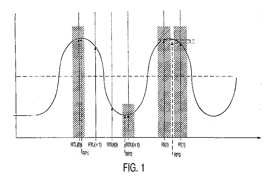
- FIG. 1 shows some waveforms of an analog data signal, the data bits are modulated asynchronously.
- This analog data signal is sampled such that certain samples, in the figure the samples RTL (0), RTL (+1), RTU (0), RTU (+1) as well as RI (0) and RI (1) arise. Because the sampling frequency does not match the modulation frequency of the data signal is coupled and also no fixed relationship to this must have, the positions of the samples relative to the positions of the Data bits are arbitrary or shift in relation to them.
- the arrangement determines for each position of a data bit to be recovered whether this lies in a tolerance window around a real sample value. Is that the case, so is the sample in whose tolerance window the position of the to be recovered Bits is set as the value for this bit to be recovered.
- FIG. 1 Such an example is shown in FIG. 1 for the data bit RP3 to be recovered. It can be seen in the figure that the position of the data bit to be recovered RP3 is not in a tolerance window of a sample. Rather, it lies between the two samples RI (0) and RI (1). Therefore, to determine the value of the data bits RP3 to be recovered these two samples, which are on either side of the position of the data bit RP3 to be recovered are used to determine this data bit used. This can advantageously be done in such a way that from the two Samples RI (0) and RI (1) an average is formed.
- FIG. 2 A block diagram of an arrangement according to the invention shown in FIG. 2 shows one Unit 1 for bit position calculation.
- the unit 1 is supplied with a phase signal Ph which, in the manner explained above, the phase relationship of the data bits of the data signal to one specifies the specified starting point. Is the data signal, for example? a teletext signal, this phase signal gives the position of the data bits within one Image line.
- the unit 1 for bit position calculation becomes a reset signal Res and Increment signal supplied Incr.
- the reset signal resets the whole arrangement what for example in the case of a teletext signal at the beginning of each picture line.
- the Increment signal is a clock signal that specifies the working clock of the arrangement.
- the unit 1 for bit position calculation is based on the phase signal Ph and The known modulation frequency of the data signal determines which positions the have data bits to be recovered. In the illustration according to FIG. 1, these are for example the positions of the data bits RP1, RP2 and RP3 to be recovered.
- the unit 1 for bit position calculation transfers these positions to a unit 2 Address calculation further, which determines addresses from the values of the positions. These addresses relate to real ones stored in an input buffer memory 3 Samples.
- the unit 2 for address calculation thus determines from that of the Unit 1 supplied signal those addresses of samples in the input buffer 3, which may be relevant for the recovery of a respective data bit can.
- the address signal which unit 2 emits for address calculation By means of the address signal which unit 2 emits for address calculation, the corresponding samples are addressed in the input buffer memory 3.
- the Values of these addressed samples are sent to a unit 4 for bit value calculation passed on.
- Unit 4 is the unit that determines the actual determination of the Makes bit values.
- the unit 4 determines the tolerance window around that Input buffer 3 delivered samples around and takes the above Decide whether a sample can be adopted immediately or whether it can be taken from an average is calculated for two samples.
- the unit 4 can set threshold values stored in a table memory 5 access, which can be used adaptively in such a way that the threshold values depending on the maximum amplitude of the samples. It will that is, depending on the actually occurring maximum values of the samples in the A corresponding cutting level is addressed in the table. With the help of this cutting level can then the decision can be made as to whether the respective data bit is a logical one first or a logical second state.
- the arrangement 4 for bit value calculation is also capable of an error signal E then to be given if a sufficient number of data bits is not recognized, ie if either the detection or the data signal is disturbed.
- the unit 4 for bit value calculation sets the values of the recovered bits in one Output buffer 6 from which by means of the unit 1 for bit position calculation is addressable so that the detected recovered data bit values from the output buffer memory 6 are readable.
- a controller 7 is also provided, which controls the overall arrangement so that the operations described above in the desired manner and order occur.
Landscapes
- Engineering & Computer Science (AREA)
- Signal Processing (AREA)
- Multimedia (AREA)
- Computer Networks & Wireless Communication (AREA)
- Television Systems (AREA)
- Digital Transmission Methods That Use Modulated Carrier Waves (AREA)
- Synchronisation In Digital Transmission Systems (AREA)
- Picture Signal Circuits (AREA)
Abstract
Description
dass die Anordnung für jedes rückzugewinnende Datenbit feststellt, ob dessen Position in einem Toleranzfenster vorgegebener Breite um die Position eines Abtastwertes herum liegt, dass die Anordnung, sollte dies der Fall sein, den Wert des in dem Toleranzfenster liegenden Abtastwertes für die Rückgewinnung des Datenbits einsetzt
und dass die Anordnung in dem Fall, dass die Position eines rückzugewinnenden Datenbits nicht in einem Toleranzfenster um die Position eines Abtastwertes liegt, die beiden Abtastwerte, die der Position des rückzugewinnenden Datenbits beiderseits benachbart positioniert sind, für die Rückgewinnung des Datenbits heranzieht.
Claims (6)
- Anordnung zur Rückgewinnung von Datenbits eines Datensignals, das in Form digitaler Abtastwerte vorliegt und dem die Datenbits mit bekannter Modulationsfrequenz asynchron aufmoduliert sind, wobei der Anordnung ein Phasensignal zugeführt wird, welches die Phasenlage der Datenbits des abgetasteten Datensignals relativ zu einem vorgegebenen Startpunkt liefert,
dadurch gekennzeichnet,dass die Anordnung aus dem Phasensignal und der bekannten Modulationsfrequenz der Datenbits die Positionen der rückzugewinnenden Datenbits bestimmt,dass die Anordnung für jedes rückzugewinnende Datenbit feststellt, ob dessen Position in einem Toleranzfenster vorgegebener Breite um die Position eines Abtastwertes herum liegt, dass die Anordnung, sollte dies der Fall sein, den Wert des in dem Toleranzfenster liegenden Abtastwertes für die Rückgewinnung des Datenbits einsetztund dass die Anordnung in dem Fall, dass die Position eines rückzugewinnenden Datenbits nicht in einem Toleranzfenster um die Position eines Abtastwertes liegt, die beiden Abtastwerte, die der Position des rückzugewinnenden Datenbits beiderseits benachbart positioniert sind, für die Rückgewinnung des Datenbits heranzieht. - Anordnung nach Anspruch 1,
dadurch gekennzeichnet,
dass in dem Fall, in dem die Position eines rückzugewinnenden Datenbits nicht in einem Toleranzfenster um die Position eines Abtastwertes liegt, aus den beiden Abtastwerten, die der Position des rückzugewinnenden Datenbits beiderseits benachbart positioniert sind, ein neuer Stützwert gebildet und für die Rückgewinnung des Datenbits eingesetzt wird. - Anordnung nach Anspruch 1,
dadurch gekennzeichnet,
dass die Toleranzfenster vorzugsweise eine Breite von etwa +/- 20 Grad, bezogen auf eine Periodenlänge von 360 Grad der Datenbits des Datensignals, aufweisen. - Anordnung nach Anspruch 1,
dadurch gekennzeichnet.
dass für die Rückgewinnung der Datenbits aus den errechneten oder übernommenen Abtastwerten Amplituden-Schneidepegel vorgesehen sind, welche adaptiv gestaltet sind und deren Amplitudenwerte sich vorzugsweise an den Maximalamplituden der errechneten oder übernommenen Abtastwerte orientieren. - Anordnung nach Anspruch 1,
dadurch gekennzeichnet,
dass die Breite des Toleranzbandes adaptiv gestaltet ist, wobei die Breite des Toleranzbandes je nach gewünschter und/oder festgestellter Erkennungssicherheit eingestellt wird. - Anordnung nach Anspruch 1,
dadurch gekennzeichnet.
dass es sich bei dem Datensignal um ein Teletextsignal eines Videosignals handelt und dass die Abtastfrequenz, mit der das Teletextsignal abgetastet wurde, mit der Zeilenfrequenz des Videosignals verkoppelt ist.
Applications Claiming Priority (2)
| Application Number | Priority Date | Filing Date | Title |
|---|---|---|---|
| DE19956937A DE19956937A1 (de) | 1999-11-26 | 1999-11-26 | Anordnung zur Rückgewinnung von Datenbits eines Datensignals |
| DE19956937 | 1999-11-26 |
Publications (3)
| Publication Number | Publication Date |
|---|---|
| EP1104192A2 true EP1104192A2 (de) | 2001-05-30 |
| EP1104192A3 EP1104192A3 (de) | 2003-11-12 |
| EP1104192B1 EP1104192B1 (de) | 2012-10-17 |
Family
ID=7930425
Family Applications (1)
| Application Number | Title | Priority Date | Filing Date |
|---|---|---|---|
| EP00204063A Expired - Lifetime EP1104192B1 (de) | 1999-11-26 | 2000-11-17 | Anordnung zur Rückgewinnung von Datenbits eines Datensignals |
Country Status (5)
| Country | Link |
|---|---|
| US (1) | US6665018B1 (de) |
| EP (1) | EP1104192B1 (de) |
| JP (1) | JP4592928B2 (de) |
| KR (1) | KR100819342B1 (de) |
| DE (1) | DE19956937A1 (de) |
Families Citing this family (1)
| Publication number | Priority date | Publication date | Assignee | Title |
|---|---|---|---|---|
| DE19956937A1 (de) * | 1999-11-26 | 2001-05-31 | Philips Corp Intellectual Pty | Anordnung zur Rückgewinnung von Datenbits eines Datensignals |
Family Cites Families (13)
| Publication number | Priority date | Publication date | Assignee | Title |
|---|---|---|---|---|
| DE59009539D1 (de) * | 1990-08-29 | 1995-09-21 | Itt Ind Gmbh Deutsche | Signal-Abtrennvorrichtung. |
| JPH06204798A (ja) * | 1992-12-28 | 1994-07-22 | Hitachi Cable Ltd | 非同期サンプリング周波数変換の補間方式 |
| JPH07170500A (ja) * | 1993-12-15 | 1995-07-04 | Sony Corp | データサンプリング方法 |
| FR2722051B1 (fr) * | 1994-07-01 | 1996-08-02 | Thomson Consumer Electronics | Procede et dispositif de donnees asynchrones sur un signal numerique |
| FR2728409B1 (fr) * | 1994-12-16 | 1997-03-14 | Sgs Thomson Microelectronics | Circuit de restitution de bits transmis de maniere asynchrone |
| FR2729019B1 (fr) * | 1994-12-30 | 1997-03-21 | Sgs Thomson Microelectronics | Circuit de restitution de bits transmis par un signal serie |
| FR2731125B1 (fr) * | 1995-02-28 | 1997-05-16 | Sgs Thomson Microelectronics | Circuit de traitement d'un signal asynchrone presentant periodiquement des salves de synchronisation |
| US5555025A (en) * | 1995-06-07 | 1996-09-10 | Intel Corporation | Apparatus and method for performing asynchronous multi-standard VBI data extraction |
| US5657088A (en) * | 1995-12-22 | 1997-08-12 | Cirrus Logic, Inc. | System and method for extracting caption teletext information from a video signal |
| JPH1013796A (ja) * | 1996-06-25 | 1998-01-16 | Mitsubishi Electric Corp | 文字多重データサンプリング回路 |
| US5812207A (en) * | 1996-12-20 | 1998-09-22 | Intel Corporation | Method and apparatus for supporting variable oversampling ratios when decoding vertical blanking interval data |
| KR100296638B1 (ko) * | 1998-04-24 | 2001-09-06 | 윤종용 | 문자다중방송 수신 데이터 검출회로 및 검출방법 |
| DE19956937A1 (de) * | 1999-11-26 | 2001-05-31 | Philips Corp Intellectual Pty | Anordnung zur Rückgewinnung von Datenbits eines Datensignals |
-
1999
- 1999-11-26 DE DE19956937A patent/DE19956937A1/de not_active Withdrawn
-
2000
- 2000-11-17 EP EP00204063A patent/EP1104192B1/de not_active Expired - Lifetime
- 2000-11-22 JP JP2000356453A patent/JP4592928B2/ja not_active Expired - Fee Related
- 2000-11-25 KR KR1020000070730A patent/KR100819342B1/ko not_active Expired - Fee Related
- 2000-11-27 US US09/722,805 patent/US6665018B1/en not_active Expired - Lifetime
Also Published As
| Publication number | Publication date |
|---|---|
| DE19956937A1 (de) | 2001-05-31 |
| EP1104192B1 (de) | 2012-10-17 |
| US6665018B1 (en) | 2003-12-16 |
| EP1104192A3 (de) | 2003-11-12 |
| JP2001203765A (ja) | 2001-07-27 |
| KR100819342B1 (ko) | 2008-04-04 |
| KR20010051963A (ko) | 2001-06-25 |
| JP4592928B2 (ja) | 2010-12-08 |
Similar Documents
| Publication | Publication Date | Title |
|---|---|---|
| DE69814931T2 (de) | Datenerfassungssystem mit einer schaltung zum umformen eines hochfrequenten analogen eingangssignals in eine anzahl von numerischen signalen | |
| DE2751973A1 (de) | Schaltungsanordnung fuer die ueberwachung von stromversorgungsnetzen auf stoerungen | |
| DE2420830A1 (de) | Verfahren und vorrichtung zur bandbreitenkompression | |
| EP0092750A1 (de) | System zur Übertragung von Informationstelegrammen | |
| DE2558264B2 (de) | Verfahren zur Verdichtung binärer Bilddaten | |
| EP0491422B1 (de) | Schaltungsanordnung zur Taktumsetzung eines digitalen Signals | |
| DE2634426A1 (de) | Bandkompressionseinrichtung | |
| EP1104192B1 (de) | Anordnung zur Rückgewinnung von Datenbits eines Datensignals | |
| EP0514629A2 (de) | Verfahren zur Demodulation und Synchronisation für digital modulierte Signale | |
| DE2704756C2 (de) | Digital-Analog-Umsetzer | |
| DE3331205C2 (de) | ||
| DE3804080A1 (de) | Digitale decodiervorrichtung | |
| DE10149512B4 (de) | Verfahren und Vorrichtung zur Synchronisation der Datenübertragung zwischen zwei Schaltungen | |
| DE2853058A1 (de) | Einrichtung zur taktrueckgewinnung in einer empfangsstation eines digitalen datenuebertragungssystems | |
| WO2005071847A1 (de) | Verfahren zur speicherung von prozesssignalen einer technischen anlage | |
| DE1287114B (de) | Verfahren und Anordnung zur Verringerung der statistischen Stoerungen in einem Fernsehbild | |
| DE3937055C2 (de) | ||
| EP1780637A1 (de) | Verfahren zur Zurücknahme ausgeführter Aktionen mittels einer grafischen Benutzeroberfläche | |
| DE2741823C3 (de) | Kanalüberwachungssystem | |
| DE3832330A1 (de) | Schaltungsanordnung zur ableitung von horizontalfrequenten und veritikalfrequenten impulsen | |
| DE69208462T2 (de) | Vorrichtung zum befestigen eines dehnbares teiles an eine profilstrecke | |
| EP0536429B1 (de) | Gerät zum Verarbeiten von in Zeilen aufgeteilten Videosignalen | |
| DE19956947A1 (de) | Anordnung zur Feststellung der Phasenlage eines Datensignals | |
| EP1454150A1 (de) | Verfahren und anordnung zum graphischen darstellen der i- und/oder q- komponenten von digital modulierten hochfrequenzsignalen | |
| EP0420321A2 (de) | Synchronsignal-Detektor |
Legal Events
| Date | Code | Title | Description |
|---|---|---|---|
| PUAI | Public reference made under article 153(3) epc to a published international application that has entered the european phase |
Free format text: ORIGINAL CODE: 0009012 |
|
| AK | Designated contracting states |
Kind code of ref document: A2 Designated state(s): AT BE CH CY DE DK ES FI FR GB GR IE IT LI LU MC NL PT SE TR |
|
| AX | Request for extension of the european patent |
Free format text: AL;LT;LV;MK;RO;SI |
|
| RAP1 | Party data changed (applicant data changed or rights of an application transferred) |
Owner name: KONINKLIJKE PHILIPS ELECTRONICS N.V. Owner name: PHILIPS CORPORATE INTELLECTUAL PROPERTY GMBH |
|
| RAP1 | Party data changed (applicant data changed or rights of an application transferred) |
Owner name: PHILIPS INTELLECTUAL PROPERTY & STANDARDS GMBH Owner name: KONINKLIJKE PHILIPS ELECTRONICS N.V. |
|
| PUAL | Search report despatched |
Free format text: ORIGINAL CODE: 0009013 |
|
| AK | Designated contracting states |
Kind code of ref document: A3 Designated state(s): AT BE CH CY DE DK ES FI FR GB GR IE IT LI LU MC NL PT SE TR |
|
| AX | Request for extension of the european patent |
Extension state: AL LT LV MK RO SI |
|
| 17P | Request for examination filed |
Effective date: 20040512 |
|
| AKX | Designation fees paid |
Designated state(s): DE FR GB |
|
| RAP1 | Party data changed (applicant data changed or rights of an application transferred) |
Owner name: NXP B.V. |
|
| RAP1 | Party data changed (applicant data changed or rights of an application transferred) |
Owner name: TRIDENT MICROSYSTEMS (FAR EAST) LTD. |
|
| GRAP | Despatch of communication of intention to grant a patent |
Free format text: ORIGINAL CODE: EPIDOSNIGR1 |
|
| RIC1 | Information provided on ipc code assigned before grant |
Ipc: H04N 7/035 20060101AFI20120509BHEP Ipc: H04L 7/033 20060101ALI20120509BHEP |
|
| GRAS | Grant fee paid |
Free format text: ORIGINAL CODE: EPIDOSNIGR3 |
|
| GRAA | (expected) grant |
Free format text: ORIGINAL CODE: 0009210 |
|
| AK | Designated contracting states |
Kind code of ref document: B1 Designated state(s): DE FR GB |
|
| REG | Reference to a national code |
Ref country code: GB Ref legal event code: FG4D Free format text: NOT ENGLISH |
|
| REG | Reference to a national code |
Ref country code: DE Ref legal event code: R096 Ref document number: 50016270 Country of ref document: DE Effective date: 20121213 |
|
| PLBE | No opposition filed within time limit |
Free format text: ORIGINAL CODE: 0009261 |
|
| STAA | Information on the status of an ep patent application or granted ep patent |
Free format text: STATUS: NO OPPOSITION FILED WITHIN TIME LIMIT |
|
| 26N | No opposition filed |
Effective date: 20130718 |
|
| REG | Reference to a national code |
Ref country code: DE Ref legal event code: R097 Ref document number: 50016270 Country of ref document: DE Effective date: 20130718 |
|
| REG | Reference to a national code |
Ref country code: GB Ref legal event code: 732E Free format text: REGISTERED BETWEEN 20131107 AND 20131113 |
|
| REG | Reference to a national code |
Ref country code: FR Ref legal event code: TP Owner name: ENTROPIC COMMUNICATIONS, INC., US Effective date: 20131119 |
|
| PGFP | Annual fee paid to national office [announced via postgrant information from national office to epo] |
Ref country code: GB Payment date: 20131127 Year of fee payment: 14 Ref country code: DE Payment date: 20131127 Year of fee payment: 14 |
|
| PGFP | Annual fee paid to national office [announced via postgrant information from national office to epo] |
Ref country code: FR Payment date: 20141118 Year of fee payment: 15 |
|
| REG | Reference to a national code |
Ref country code: DE Ref legal event code: R119 Ref document number: 50016270 Country of ref document: DE |
|
| GBPC | Gb: european patent ceased through non-payment of renewal fee |
Effective date: 20141117 |
|
| PG25 | Lapsed in a contracting state [announced via postgrant information from national office to epo] |
Ref country code: DE Free format text: LAPSE BECAUSE OF NON-PAYMENT OF DUE FEES Effective date: 20150602 Ref country code: GB Free format text: LAPSE BECAUSE OF NON-PAYMENT OF DUE FEES Effective date: 20141117 |
|
| REG | Reference to a national code |
Ref country code: FR Ref legal event code: ST Effective date: 20160729 |
|
| PG25 | Lapsed in a contracting state [announced via postgrant information from national office to epo] |
Ref country code: FR Free format text: LAPSE BECAUSE OF NON-PAYMENT OF DUE FEES Effective date: 20151130 |