EP1104191A2 - Anordnung zur Feststellung der Phasenlage eines Datensignals - Google Patents
Anordnung zur Feststellung der Phasenlage eines Datensignals Download PDFInfo
- Publication number
- EP1104191A2 EP1104191A2 EP00204062A EP00204062A EP1104191A2 EP 1104191 A2 EP1104191 A2 EP 1104191A2 EP 00204062 A EP00204062 A EP 00204062A EP 00204062 A EP00204062 A EP 00204062A EP 1104191 A2 EP1104191 A2 EP 1104191A2
- Authority
- EP
- European Patent Office
- Prior art keywords
- samples
- signal
- arrangement
- data signal
- bits
- Prior art date
- Legal status (The legal status is an assumption and is not a legal conclusion. Google has not performed a legal analysis and makes no representation as to the accuracy of the status listed.)
- Granted
Links
Images

Classifications
-
- H—ELECTRICITY
- H03—ELECTRONIC CIRCUITRY
- H03M—CODING; DECODING; CODE CONVERSION IN GENERAL
- H03M7/00—Conversion of a code where information is represented by a given sequence or number of digits to a code where the same, similar or subset of information is represented by a different sequence or number of digits
-
- H—ELECTRICITY
- H04—ELECTRIC COMMUNICATION TECHNIQUE
- H04N—PICTORIAL COMMUNICATION, e.g. TELEVISION
- H04N7/00—Television systems
- H04N7/025—Systems for the transmission of digital non-picture data, e.g. of text during the active part of a television frame
- H04N7/035—Circuits for the digital non-picture data signal, e.g. for slicing of the data signal, for regeneration of the data-clock signal, for error detection or correction of the data signal
-
- H—ELECTRICITY
- H04—ELECTRIC COMMUNICATION TECHNIQUE
- H04L—TRANSMISSION OF DIGITAL INFORMATION, e.g. TELEGRAPHIC COMMUNICATION
- H04L7/00—Arrangements for synchronising receiver with transmitter
- H04L7/02—Speed or phase control by the received code signals, the signals containing no special synchronisation information
- H04L7/033—Speed or phase control by the received code signals, the signals containing no special synchronisation information using the transitions of the received signal to control the phase of the synchronising-signal-generating means, e.g. using a phase-locked loop
- H04L7/0334—Processing of samples having at least three levels, e.g. soft decisions
-
- H—ELECTRICITY
- H04—ELECTRIC COMMUNICATION TECHNIQUE
- H04L—TRANSMISSION OF DIGITAL INFORMATION, e.g. TELEGRAPHIC COMMUNICATION
- H04L7/00—Arrangements for synchronising receiver with transmitter
- H04L7/04—Speed or phase control by synchronisation signals
Definitions
- the invention relates to an arrangement for determining the phase position of an in shape digital samples of existing data signal with asynchronous modulated data, whose modulation frequency is known.
- the data signal is in the form of digital samples. Especially if the sampling frequency with which the digital samples were obtained, not with the Modulation frequency of the data is coupled, it is not known which sample which bit represents and where this sample lies within the course of this bit. This causes considerable problems when decoding the bits or the decoding is susceptible to interference, for example susceptible to noise.
- EP-A-0 472 756 is a signal separating device known which is used to separate a teletext signal from a video signal.
- the circuit works very complex and has an integrating device, the half-state signal characterizing the signal means of the individual bits of the data signal and emits a residual signal.
- a residual value signal evaluation device evaluates the each residual value and uses a selection control signal to determine how the value of the current signal bits should be estimated.
- a selection device is available for this, those from the current sample and the previous one or the subsequent sample value, the respective lead mean or lag mean forms and uses the selection control signal to select the value suitable for the estimate.
- a further provided phase correction device evaluates one from an edge logic device provided signal pattern, which indicates whether the current sample value approaches an edge of a signal. The same facility then controls a change in Integration period when the residual value signal is within a predetermined residual value signal range. This arrangement works very complex and can only make a kind of estimate of the location of the individual bits.
- the arrangement has means which carry out a first and / or a second method for determining the bit positions of the sampled data signal, that at least one set of three or five consecutive samples is sought in the first method, the mean sample of which is larger or smaller than the adjacent outer samples of the set and for which the difference (s) between those outer samples is the same distance from each other have a mean sample value, fall below a predetermined threshold value, the position of the mean sample value and an assigned position number indicating the position of the bit in the data signal being stored in a memory when such a data record is found, that in the second method a set of four consecutive samples is sought, the two average samples of which are approximately the same size and whose average size is smaller or larger than the average size of the two outer samples and in which the difference between the outer samples falls below a predetermined threshold value, when such a data record is found, the bit position in the middle between the two middle samples and an assigned position number are stored in a memory (10), and that the arrangement of at least two determined bit positions
- the invention is concerned with the phase relationship of the individual bits of the asynchronous determine modulated data and, if necessary, a downstream decoder, which is not part of the invention and which determines the data, a phase signal provide the decoder the phase position of the asynchronous modulated data in the Data signal indicates.
- the arrangement according to the invention must be used be able to determine the exact position of the bits of the data signal.
- means are provided in the arrangement, which have a first and / or a second Perform procedures in which the bit positions of the sampled data signal are determined become.
- certain bit positions are selected which are striking Have position relative to the samples, so that from the samples relatively precise on the Position of the bits can be closed.
- these means search for a set of three or five successive samples, for which the following conditions apply:
- the mean sample of these three or five or more samples must be greater or less than all of the outer samples adjacent to it, that is, as the remaining two or four samples of this set of samples. Furthermore, the difference between the outer samples, which are equally spaced from the mean distance value, must be minimal. If three samples are used in one set for this procedure, the difference between these two values must be minimal. If five samples in a set are used to carry out this method, the difference between the first and the last sample of this set of samples must be minimal and also the difference between the second and fourth samples of this set must also be minimal.
- the mean sample value of this Set of samples quite exactly a maximum or a minimum in the waveform represents the data signal. So this sample pretty much represents it exactly one central position of a bit in the data signal. Since this is exactly what is wanted If such a data record is found, for which the conditions described above are satisfied, the position of the average sample value is stored in a memory. The position of this bit in the data signal is also stored, that is for example the number of bits from a predeterminable starting point. Also this value is stored as a position number in the memory.
- the means carry a second Method by looking for a set of four consecutive samples is, in which the difference between the two middle samples a predetermined Falls below the threshold and at which these two samples are both smaller or both are larger than the two outer samples of this set. Furthermore, the Difference of the outer samples, if necessary, a predetermined threshold fall below. If such a data record is found, it can be concluded that that the center of the bit to which this record belongs belongs pretty much one position between the positions of the two middle samples. Thus one Bit position in the middle between these two samples and again the assigned one Position number indicating the position of the bit in the data signal in one Memory saved. Here too, that applies in the course of carrying out the procedure several such records are found that meet the specified conditions.
- the arrangement now determines from the stored bit positions and position numbers the phase signal. This is possible because the length of the bits, i.e. their period length, results from the known modulation frequency is also known. There will be at least two of the stored determined bit positions used, it being known which positions of this bit and how many bits it is. So it is for example for two stored bit positions known by how many bits these positions are apart and which positions the centers of the bits have. From these Both known values can be at a known distance between the centers of the bits known positions of the centers of the bits and with a known period length immediately the phase position can be determined. By evaluating the quality of the individual measuring points the exactness of the phase position to be determined can be increased. The order is thus able to determine the phase position of the data signal or the phase position of the bits thereof to specify the sampled data signal relative to a predeterminable starting point.
- downstream decoder which is not part of the invention easy to decode the bits because the downstream decoder uses the Phase signal is known exactly what positions the centers of the bits of the data signal to have. This means that the decoder can immediately determine which samples which positions have relative to these centers of the bits and can thus be an optimal one Carry out decoding.
- At least two of the determined bit positions are used to determine the phase signal to be used, the accuracy of the method can possibly be increased thereby be that more than two of the bit positions found to determine the phase signal be used.
- the arrangement works quite simply, because only for carrying out the procedure Differences have to be formed and no further estimates are necessary.
- the bit positions and also the phase signal can be determined by calculations.
- the All or part of the functions that the arrangement performs are also software realizable.
- An embodiment of the invention provided according to claim 2 provides that the two Method for determining the positions of the bits of the data signal on in the data signal provided synchronization bits are used, for example one frame each of the data bits are prefixed. This can then be done from these synchronization bits Phase signal can be obtained, which for after the synchronization bits in the data signal transmitted data bits can be applied. This is the transfer after Synchronization bits the phase of the data signal for the subsequent data block known and it can be an optimal downstream decoder Phase signal for the decoding of the data bits are provided.
- phase signal In a further embodiment of the invention according to claim 3 is minimized Effort for the generation of the phase signal only one of the found and stored bit positions according to the first and the second method. There may be slightly different results from the stored bit positions Phase positions, an average value is formed between these and output as a phase signal. With minimal effort, this is still a very precise phase signal can be generated.
- the arrangement of the stored bit positions, the assigned position numbers and the known modulation frequency the phase signal to calculate is provided from the distances of the determined bit positions and the assigned position numbers a determination of the modulation frequency of the data signal.
- This information can be used for this purpose, for example identification of the data signal, i.e. to check whether the modulation frequency corresponds to the expected modulation frequency or by means of the Modulation frequency determine what type of data signal it is.
- This Information can be, for example, if the data signal is a teletext signal of a video signal is used to determine which transmission standard has the teletext signal.
- an error signal if within a predetermined period of time does not determine at least a predetermined number of bit numbers becomes. It can then be assumed that this is not the case either expected data signal or a disturbed data signal.
- the arrangement can be advantageous, as in a further embodiment 8 is provided, can be used to determine the phase position of teletext signals within a television signal.
- the position of the teletext bits within a Picture line of the television signal may fluctuate.
- the decoder according to the invention can advantageously enable decoders to be reliably decoded Arrange a phase signal for each image line.
- the edge detector provided there can only be used for such samples to be included in the methods described above that belong to pulses that have at least one predetermined flank height. It can thus be achieved that individual interference peaks within the data signal cannot be recognized as a bit position. Further is a downstream according to this claim by means of the output signal of the edge detector Bit counter driven, which immediately the position numbers of the individual bits delivers and its value in the implementation of the method directly as to be saved Item number can be used.
- the asynchronous modulated data signal is a sampled teletext signal acts.
- the teletext signal is transmitted line by line within a television signal.
- bits of the teletext signal are transmitted in each picture line of the television signal are first transmitted a few synchronization bits, based on which the inventive Arrangement provides the phase signal, which subsequently for position determination of data bits subsequently transmitted are used in the teletext signal within each picture line becomes.
- This phase signal can in a downstream decoder, which is not Part of the invention is advantageously used for decoding the bits because the exact position of the bits relative to the samples is known on the basis of this phase signal is.
- the procedure for decoding is not the subject of the invention, whose task is to provide a phase signal that has an optimal decoding enables.
- the arrangement according to the invention provides for the decoding of such a teletext signal a phase signal individually for each bit line, the phase position for the respective bit line which indicates teletext bits relative to a predeterminable starting point. This is necessary because the positions of the bits or the phase position of the teletext signal from picture line to picture line can fluctuate.
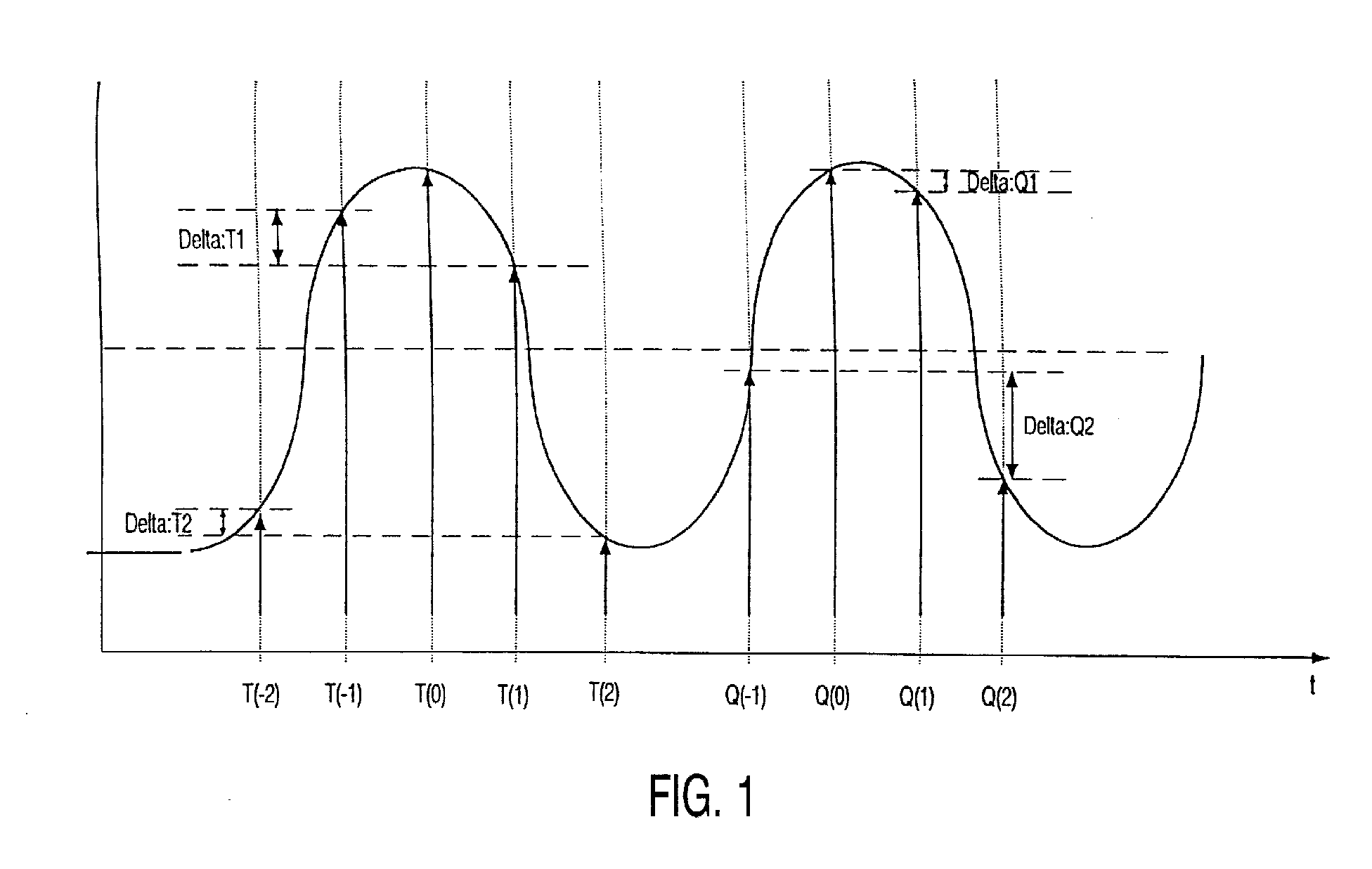
- Fig. 1 are the waveforms of two synchronizing bits and their samples and positions of such an analog teletext signal, as is the case, for example, in a television signal may be included, plotted over time.
- samples of this signal are also identified by arrows.
- the representation shows that due to the uncoupled sampling frequency with which the samples generated, these are arbitrary with respect to the bit positions of the synchronization bits can shift and because of the possibly not coupled frequencies can also drift.
- FIG. 1 is used to explain the two methods on the basis of the first bit shown in FIG. 1, the first method and on the basis of the second 1, the second method is explained below.
- the first method looks for a set of samples for which two conditions must be fulfilled.
- the mean sample must be a larger or smaller Have value as two or four adjacent samples.
- the differences of the adjacent samples may be minimal, the difference between Samples are calculated, each having the same position relative to the mean Have sample. These differences must each have a predetermined threshold fall below. If this is the case, the bit position determined is that of the position of the corresponds to the mean sample value of this data record. Furthermore, the associated position number is stored, which indicates the position of the bit in the data signal.
- an average sample value T (0) is entered, the value of which is greater than the values of the sample values T (-1) and T (1) immediately surrounding it.
- the conditions of the second method are that the values of the two middle samples, in the example of FIG. 1, the values Q (0) and Q (1) are larger or smaller values than the adjacent samples, in the example the samples Q (-1) and Q (2).
- Based on the stored bit positions and the respectively assigned position numbers can with known modulation frequency of the data signal and thus known period length of the bits of the data signal are immediately calculated a phase signal which indicates the phase position of the bits of the data signal relative to a predeterminable starting point.
- phase signal For the determination of the phase signal, those using the first and / or the second Bit positions and assigned position numbers determined using the method are used become. In the simplest case, a bit position is determined for each method and for determination of the phase signal. Several bit positions can also be used for each method can be determined from which those are selected for whom those described above Differences are minimal. If necessary, you can use the individual bit positions the phase positions to be determined differ slightly from each other. In this Trap can advantageously be drawn from the phase positions and as a phase signal be issued.
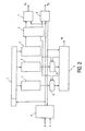
- a block diagram shown in FIG. 2 shows an arrangement according to the invention Determination of the phase position of a data signal.
- the data signal can be, for example is a teletext signal.
- the teletext signal is at a sampling frequency that is not coupled to the modulation frequency of the bits of the teletext signal.
- the corresponding samples are stored in a buffer memory 1 saved. This can be the case, for example, for all samples of an image line of the TV signal happen.
- An address counter 2 is provided within the arrangement, on the one hand a reset signal R is supplied, which is read out, for example, at the beginning of each new image line so that the remaining counter starts counting again. Furthermore, the address counter 2 an increment signal is supplied, so that the address counter 2 with this increment signal high counts, so that the individual samples, for example of an image line, are stored in the buffer memory 1 are gradually addressed.
- bits thus gradually addressed become means 3 for carrying out the first Method and means 4 supplied to carry out the second method.
- the means 3 and 4 determine in the manner described above data records for which the respective conditions of the two processes are met.
- the bit positions determined in the process are stored in a first memory 9 and in a second memory 10 saved.
- an edge detector 5 which is gradually based on the addressed samples the individual bits identified. This is done in such a way that only those bits are taken into account which at least according to the sample values have a predetermined flank height.
- the downstream bit counter 6 counts these bits.
- phase signal Ph Phase signal Ph
- both means 3 and 4 can be provided, but it can be from the bit positions only one value of the two methods in each of the memories 9 and 10 Unit 11 can be used to determine the phase signal.
- a further possibility consists of possibly several in the memory 9 or 10 respectively stored bit positions are those bit positions for determining the Select phase signal for which the differences to be calculated are minimal. It a qualitative selection can be made from the bit positions.
- phase positions become an average drawn and output as a phase signal Ph.
- phase position can be determined from these two bit positions be determined and output as a phase signal Ph.
- a unit 7 for frequency checking and a unit 8 for error checking are also provided in the arrangement. These two units are basically optional; but they can increase the operational reliability of the arrangement.
- the unit 7 for frequency testing supplies an error signal E F , which appears when the modulation frequency of the data signal is not within a predetermined frame. Then it can be concluded that it is not the desired data signal.
- Unit 7 can determine this frequency from the number of determined bits that are supplied by bit counter 6 and the number of addresses that are supplied by address counter 2. If this frequency is not within a predetermined frame, the frequency error signal E F is output and the arrangement stops the calculation of the phase signal Ph.
- the unit 8 for error checking counts those bits that are within a predetermined Timeframe can be recognized.
- the time frame is determined by the address data of the Address counter determines and the number of bits results from the bit counter 6. Will a minimum number of bits is not recognized within a predetermined period of time also the determination of the phase signal Ph stopped. This is done by the Unit 8 a corresponding error signal to both the address counter 2 and the Unit 11 for determining the phase signal delivers.
Landscapes
- Engineering & Computer Science (AREA)
- Multimedia (AREA)
- Signal Processing (AREA)
- Theoretical Computer Science (AREA)
- Synchronisation In Digital Transmission Systems (AREA)
- Television Systems (AREA)
- Signal Processing For Digital Recording And Reproducing (AREA)
Abstract
Description
dass bei dem ersten Verfahren wenigsten ein Satz von jeweils drei oder fünf aufeinanderfolgenden Abtastwerten gesucht wird, deren mittlerer Abtastwert größer oder kleiner als die ihm benachbarten äußeren Abtastwerte des Satzes ist und bei denen die Differenz(en) derjenigen äußeren Abtastwerte, die jeweils gleichen Abstand zum mittleren Abtastwert haben, einen vorgegebenen Schwellwert unterschreiten, wobei bei Auffindung eines solchen Datensatzes die Position des mittleren Abtastwertes und eine zugeordnete, die Position des Bits in dem Datensignal angebende Positionszahl in einem Speicher gespeichert werden,
dass bei dem zweiten Verfahren ein Satz von vier aufeinanderfolgenden Abtastwerten gesucht wird, deren beide mittlere Abtastwerte näherungsweise gleich groß und deren mittlere Größe kleiner oder größer als die mittlere Größe der beiden äußeren Abtastwerte ist und bei denen die Differenz der äußeren Abtastwerte einen vorgegebenen Schwellwert unterschreitet, wobei bei Auffindung eines solchen Datensatzes die Bitposition in der Mitte zwischen den beiden mittleren Abtastwerten und eine zugeordnete Positionszahl in einem Speicher (10) gespeichert wird,
und dass die Anordnung aus wenigstens zwei ermittelten Bitpositionen, den diesen zugeordneten Positionszahlen und der Periodenlänge der Bits des Datensignals ein Phasensignal bestimmt, welches die Phasenlage der Bits des abgetasteten Datensignals relativ zu einem vorgebbaren Startpunkt liefert.
Der mittlere Abtastwert dieser drei oder fünf oder mehr Abtastwerte muß größer oder kleiner als sämtliche ihn benachbarten äußeren Abtastwerte sein, also als die übrigen zwei oder vier Abtastwerte dieses Satzes von Abtastwerten. Ferner muß die Differenz der äußeren Abtastwerte, die jeweils gleichen Abstand zum mittleren Abstandswert haben, minimal sein. Werden also drei Abtastwerte in einem Satz für dieses Verfahren herangezogen, so muß die Differenz dieser beiden Werte minimal sein. Werden fünf Abtastwerte in einem Satz für die Durchführung dieses Verfahrens herangezogen, so muß die Differenz zwischen dem ersten und dem letzten Abtastwert dieses Satzes von Abtastwerten minimal sein und ferner die Differenz zwischen dem zweiten und dem vierten Abtastwert dieses Satzes ebenfalls minimal sein.
Die Einheit 7 zur Frequenzprüfung liefert ein Fehlersignal EF, welches dann erscheint, wenn die Modulationsfrequenz des Datensignals nicht in einem vorgegebenen Rahmen liegt. Dann kann darauf geschlossen werden, dass es sich nicht um das gewünschte Datensignal handelt. Diese Frequenz kann die Einheit 7 aus der Zahl der ermittelten Bits, die von dem Bitzähler 6 geliefert werden und der Zahl der Adressen, die von dem Adressenzähler 2 geliefert werden, bestimmen. Liegt dieser Frequenz nicht in einem vorgegebenen Rahmen, so wird das Frequenzfehlersignal EF ausgegeben und die Anordnung stellt die Berechnung des Phasensignals Ph ein.
Claims (10)
- Anordnung zur Feststellung der Phasenlage eines in Form digitaler Abtastwerte vorliegenden Datensignals mit asynchronen modulierten Daten, deren Modulationsfrequenz bekannt ist,
dadurch gekennzeichnet,
dass die Anordnung Mittel (3,4) aufweist, welche ein erstes und/oder ein zweites Verfahren zur Ermittlung der Bitpositionen des abgetasteten Datensignals durchführen,
dass bei dem ersten Verfahren wenigsten ein Satz von jeweils drei oder fünf aufeinanderfolgenden Abtastwerten gesucht wird, deren mittlerer Abtastwert größer oder kleiner als die ihm benachbarten äußeren Abtastwerte des Satzes ist und bei denen die Differenz(en) derjenigen äußeren Abtastwerte, die jeweils gleichen Abstand zum mittleren Abtastwert haben, einen vorgegebenen Schwellwert unterschreiten, wobei bei Auffindung eines solchen Datensatzes die Position des mittleren Abtastwertes und eine zugeordnete, die Position des Bits in dem Datensignal angebende Positionszahl in einem Speicher (9) gespeichert werden,
dass bei dem zweiten Verfahren ein Satz von vier aufeinanderfolgenden Abtastwerten gesucht wird, deren beide mittlere Abtastwerte näherungsweise gleich groß und deren mittlere Größe kleiner oder größer als die mittlere Größe der beiden äußeren Abtastwerte ist und bei denen die Differenz der äußeren Abtastwerte einen vorgegebenen Schwellwert unterschreitet, wobei bei Auffindung eines solchen Datensatzes die Bitposition in der Mitte zwischen den beiden mittleren Abtastwerten und eine zugeordnete Positionszahl in einem Speicher (10) gespeichert wird,
und dass die Anordnung aus wenigstens zwei ermittelten Bitpositionen, den diesen zugeordneten Positionszahlen und der Periodenlänge der Bits des Datensignals ein Phasensignal bestimmt, welches die Phasenlage der Bits des abgetasteten Datensignals relativ zu einem vorgebbaren Startpunkt liefert. - Anordnung nach Anspruch 1,
dadurch gekennzeichnet,
dass die Anordnung die beiden Verfahren auf in dem Datensignal vorgesehene Synchronisierbits anwendet und das daraus bestimmte Phasensignal für die Ermittlung von Datenbits zur Verfügung stellt, die in dem Datensignal nach den Synchronisierbits übertragen werden. - Anordnung nach Anspruch 1,
dadurch gekennzeichnet,
dass die Anordnung mittels des ersten und des zweiten Verfahrens jeweils wenigstens einen Satz von Abtastwerten ermittelt, der die Bedingungen am ehesten erfüllt, und dass für die Ermittlung des Phasensignals aus den mit den beiden Verfahren ermittelten Bitpositionen und den sich daraus ergebenden Phasenlagen ein Mittelwert gewählt wird. - Anordnung nach Anspruch 1 oder 2,
dadurch gekennzeichnet,
dass im ersten Verfahren jeweils drei Abtastwerte einen Satz von Abtastwerten bilden. - Anordnung nach Anspruch 1,
dadurch gekennzeichnet,
dass die Anordnung mittels der beiden Verfahren jeweils mehrere Bitpositionen und zugeordnete Positionszahlen bestimmt und aus diesen eine qualitative Auswahl in der Weise trifft, dass Bitpositionen ausgesucht werden und zur Bestimmung des Phasensignals herangezogen werden, welche aus solchen Sätzen von Abtastwerten bestimmt wurden, für die die Differenz der äußeren Abtastwerte minimal ist. - Anordnung nach Anspruch 1,
dadurch gekennzeichnet,
dass die Anordnung aus den Abständen der ermittelten Bitpositionen zueinander und den zugeordneten Positionszahlen eine Bestimmung der Modulationsfrequenz des Datensignals vornimmt, welche zur Identifikation des Datensignals herangezogen wird. - Anordnung nach Anspruch 1,
dadurch gekennzeichnet,
dass die Anordnung ein Fehlersignal auslöst, wenn innerhalb einer vorgegebenen Zeitspanne nicht wenigstens eine vorgegebene Anzahl von Bitzahlen ermittelt wird. - Anordnung nach Anspruch 1,
dadurch gekennzeichnet,
dass es sich bei dem Datensignal um ein Teletext-Signal eines Fernsehsignals handelt, das mit einer Abtastfrequenz abgetastet wurde, die mit der Zeilenfrequenz des Fernsehsignals verkoppelt ist und die vorzugsweise etwa 13,5 MHz beträgt. - Anordnung nach Anspruch 1 oder 8,
dadurch gekennzeichnet,
dass die Abtastfrequenz nicht mit der Modulationsfrequenz verkoppelt ist. - Anordnung nach Anspruch 1,
dadurch gekennzeichnet,
dass in der Anordnung ein Flankendetektor (5) vorgesehen ist, dessen Ausgangssignal dazu herangezogen wird, in die Verfahren nur diejenigen Abtastwerte einzubeziehen, die zu Impulsen gehören, die wenigstens eine vorgegebene Flankenhöhe aufweisen, und dass mittels des Ausgangssignals des Flankendetektors und eines nachgeschalteten Bitzählers (6) die Positionszahlen bestimmt werden.
Applications Claiming Priority (2)
| Application Number | Priority Date | Filing Date | Title |
|---|---|---|---|
| DE19956947A DE19956947A1 (de) | 1999-11-26 | 1999-11-26 | Anordnung zur Feststellung der Phasenlage eines Datensignals |
| DE19956947 | 1999-11-26 |
Publications (3)
| Publication Number | Publication Date |
|---|---|
| EP1104191A2 true EP1104191A2 (de) | 2001-05-30 |
| EP1104191A3 EP1104191A3 (de) | 2003-11-12 |
| EP1104191B1 EP1104191B1 (de) | 2012-11-07 |
Family
ID=7930432
Family Applications (1)
| Application Number | Title | Priority Date | Filing Date |
|---|---|---|---|
| EP00204062A Expired - Lifetime EP1104191B1 (de) | 1999-11-26 | 2000-11-17 | Anordnung zur Feststellung der Phasenlage eines Datensignals |
Country Status (5)
| Country | Link |
|---|---|
| US (1) | US6768773B1 (de) |
| EP (1) | EP1104191B1 (de) |
| JP (1) | JP2001218174A (de) |
| KR (1) | KR100790029B1 (de) |
| DE (1) | DE19956947A1 (de) |
Cited By (1)
| Publication number | Priority date | Publication date | Assignee | Title |
|---|---|---|---|---|
| EP1209912A1 (de) * | 2000-11-22 | 2002-05-29 | Mitsubishi Denki Kabushiki Kaisha | Daten-Slicer-Schaltung |
Families Citing this family (1)
| Publication number | Priority date | Publication date | Assignee | Title |
|---|---|---|---|---|
| CN112773657B (zh) * | 2019-11-08 | 2022-11-22 | 上海荣泰健康科技股份有限公司 | 按摩椅找肩控制方法 |
Family Cites Families (7)
| Publication number | Priority date | Publication date | Assignee | Title |
|---|---|---|---|---|
| FR2358056A1 (fr) * | 1976-07-09 | 1978-02-03 | Ibm France | Procede et dispositif de synchronisation de l'horloge du recepteur d'un systeme de transmissions de donnees en modulation psk |
| US4358853A (en) * | 1981-01-22 | 1982-11-09 | Codex Corporation | Digital modem transmitter |
| US4376309A (en) * | 1981-05-29 | 1983-03-08 | Bell Telephone Laboratories, Incorporated | Method and apparatus for signal-eye tracking in digital transmission systems |
| NL8700175A (nl) * | 1987-01-26 | 1988-08-16 | Philips Nv | Werkwijze voor het door middel van codesignalen overdragen van informatie, informatie-overdrachtsysteem voor het uitvoeren van de werkwijze, alsmede een verzend- en ontvangstinrichting voor toepassing in het overdrachtsysteem. |
| DE59009539D1 (de) * | 1990-08-29 | 1995-09-21 | Itt Ind Gmbh Deutsche | Signal-Abtrennvorrichtung. |
| FR2729019B1 (fr) * | 1994-12-30 | 1997-03-21 | Sgs Thomson Microelectronics | Circuit de restitution de bits transmis par un signal serie |
| US6205183B1 (en) * | 1998-05-29 | 2001-03-20 | Ericsson Inc. | Methods of suppressing reference oscillator harmonic interference and related receivers |
-
1999
- 1999-11-26 DE DE19956947A patent/DE19956947A1/de not_active Withdrawn
-
2000
- 2000-11-17 EP EP00204062A patent/EP1104191B1/de not_active Expired - Lifetime
- 2000-11-21 JP JP2000354691A patent/JP2001218174A/ja not_active Withdrawn
- 2000-11-25 KR KR1020000070622A patent/KR100790029B1/ko not_active Expired - Fee Related
- 2000-11-27 US US09/723,134 patent/US6768773B1/en not_active Expired - Fee Related
Cited By (1)
| Publication number | Priority date | Publication date | Assignee | Title |
|---|---|---|---|---|
| EP1209912A1 (de) * | 2000-11-22 | 2002-05-29 | Mitsubishi Denki Kabushiki Kaisha | Daten-Slicer-Schaltung |
Also Published As
| Publication number | Publication date |
|---|---|
| EP1104191A3 (de) | 2003-11-12 |
| US6768773B1 (en) | 2004-07-27 |
| EP1104191B1 (de) | 2012-11-07 |
| DE19956947A1 (de) | 2001-05-31 |
| KR20010051951A (ko) | 2001-06-25 |
| JP2001218174A (ja) | 2001-08-10 |
| KR100790029B1 (ko) | 2007-12-31 |
Similar Documents
| Publication | Publication Date | Title |
|---|---|---|
| DE68917026T2 (de) | Verfahren und Anordnung zur Bewegungsdetektion in einem nach einer Film-Fernseh-Umwendung erhaltenen Fernsehbild mit Zeilensprungverfahren. | |
| DE3429901C2 (de) | Verfahren und anordnung zur uebertragung von daten | |
| DE2545753A1 (de) | Anordnung zur erkennung aehnlicher objekte | |
| DE69829088T2 (de) | Verfahren und Vorrichtung zur Übertragung von Datenrahmen | |
| DE2907990A1 (de) | Verfahren und vorrichtung zum abtasten der amplitude eines signals | |
| DE2420830A1 (de) | Verfahren und vorrichtung zur bandbreitenkompression | |
| DE69930143T2 (de) | Extrahieren von zusatzdaten in einem informationssignal | |
| DE3044761A1 (de) | Digitales vergroesserungssystem fuer ein abgetastetes bild | |
| DE3111555C2 (de) | Verfahren und Vorrichtung zur Informationsspeicherung unter Anwendung früherer Aufzeichnung | |
| DE3587620T2 (de) | Logikanalysator. | |
| DE102015120242B3 (de) | Verfahren zum Betreiben eines Kommunikationsnetzwerkes, Kommunikationsnetzwerk, Steuervorrichtung und Datenverarbeitungsvorrichtung | |
| DE69008038T2 (de) | Schaltungsanordnung zur Detektion des Verlustes eines digitalen, empfangenen Signals für digitale Signalempfänger. | |
| DE2634426A1 (de) | Bandkompressionseinrichtung | |
| DE1922302A1 (de) | Zaehlsystem zum Zaehlen von Merkmalen bei der Bildanalyse unter Verwendung der Zeilenabtastung | |
| DE2625840A1 (de) | Radaranzeigesystem | |
| DE2433885A1 (de) | Verfahren und vorrichtung zum synchronisieren eines testinstruments auf ein digitales system | |
| EP1104191B1 (de) | Anordnung zur Feststellung der Phasenlage eines Datensignals | |
| DE60001520T2 (de) | Verfahren zum Testen von elektronischen Komponenten | |
| DE3035757C2 (de) | ||
| EP2446640B1 (de) | Vorrichtung und verfahren zur bestimmung eines abtastratenunterschiedes | |
| DE69011606T2 (de) | Synchronisationsverfahren des Empfängers eines Mac-Norm-Fernsehsignals. | |
| EP0420320A2 (de) | Digitale Schaltungsanordnung zur Detektion von Synchronisationsimpulsen | |
| EP0536429B1 (de) | Gerät zum Verarbeiten von in Zeilen aufgeteilten Videosignalen | |
| DE3132984A1 (de) | Logikanalysator | |
| DE3540774C2 (de) |
Legal Events
| Date | Code | Title | Description |
|---|---|---|---|
| PUAI | Public reference made under article 153(3) epc to a published international application that has entered the european phase |
Free format text: ORIGINAL CODE: 0009012 |
|
| AK | Designated contracting states |
Kind code of ref document: A2 Designated state(s): AT BE CH CY DE DK ES FI FR GB GR IE IT LI LU MC NL PT SE TR |
|
| AX | Request for extension of the european patent |
Free format text: AL;LT;LV;MK;RO;SI |
|
| RAP1 | Party data changed (applicant data changed or rights of an application transferred) |
Owner name: PHILIPS CORPORATE INTELLECTUAL PROPERTY GMBH Owner name: KONINKLIJKE PHILIPS ELECTRONICS N.V. |
|
| RAP1 | Party data changed (applicant data changed or rights of an application transferred) |
Owner name: KONINKLIJKE PHILIPS ELECTRONICS N.V. Owner name: PHILIPS INTELLECTUAL PROPERTY & STANDARDS GMBH |
|
| PUAL | Search report despatched |
Free format text: ORIGINAL CODE: 0009013 |
|
| AK | Designated contracting states |
Kind code of ref document: A3 Designated state(s): AT BE CH CY DE DK ES FI FR GB GR IE IT LI LU MC NL PT SE TR |
|
| AX | Request for extension of the european patent |
Extension state: AL LT LV MK RO SI |
|
| 17P | Request for examination filed |
Effective date: 20040512 |
|
| AKX | Designation fees paid |
Designated state(s): DE FR GB |
|
| RAP1 | Party data changed (applicant data changed or rights of an application transferred) |
Owner name: NXP B.V. |
|
| RAP1 | Party data changed (applicant data changed or rights of an application transferred) |
Owner name: TRIDENT MICROSYSTEMS (FAR EAST) LTD. |
|
| GRAP | Despatch of communication of intention to grant a patent |
Free format text: ORIGINAL CODE: EPIDOSNIGR1 |
|
| GRAS | Grant fee paid |
Free format text: ORIGINAL CODE: EPIDOSNIGR3 |
|
| GRAA | (expected) grant |
Free format text: ORIGINAL CODE: 0009210 |
|
| AK | Designated contracting states |
Kind code of ref document: B1 Designated state(s): DE FR GB |
|
| REG | Reference to a national code |
Ref country code: GB Ref legal event code: FG4D Free format text: NOT ENGLISH |
|
| REG | Reference to a national code |
Ref country code: DE Ref legal event code: R096 Ref document number: 50016274 Country of ref document: DE Effective date: 20130103 |
|
| PLBE | No opposition filed within time limit |
Free format text: ORIGINAL CODE: 0009261 |
|
| STAA | Information on the status of an ep patent application or granted ep patent |
Free format text: STATUS: NO OPPOSITION FILED WITHIN TIME LIMIT |
|
| 26N | No opposition filed |
Effective date: 20130808 |
|
| REG | Reference to a national code |
Ref country code: GB Ref legal event code: 732E Free format text: REGISTERED BETWEEN 20131107 AND 20131113 |
|
| REG | Reference to a national code |
Ref country code: DE Ref legal event code: R097 Ref document number: 50016274 Country of ref document: DE Effective date: 20130808 |
|
| REG | Reference to a national code |
Ref country code: FR Ref legal event code: TP Owner name: ENTROPIC COMMUNICATIONS, INC., US Effective date: 20131119 |
|
| PGFP | Annual fee paid to national office [announced via postgrant information from national office to epo] |
Ref country code: FR Payment date: 20141118 Year of fee payment: 15 Ref country code: GB Payment date: 20141127 Year of fee payment: 15 |
|
| PGFP | Annual fee paid to national office [announced via postgrant information from national office to epo] |
Ref country code: DE Payment date: 20151127 Year of fee payment: 16 |
|
| GBPC | Gb: european patent ceased through non-payment of renewal fee |
Effective date: 20151117 |
|
| REG | Reference to a national code |
Ref country code: FR Ref legal event code: ST Effective date: 20160729 |
|
| PG25 | Lapsed in a contracting state [announced via postgrant information from national office to epo] |
Ref country code: GB Free format text: LAPSE BECAUSE OF NON-PAYMENT OF DUE FEES Effective date: 20151117 |
|
| PG25 | Lapsed in a contracting state [announced via postgrant information from national office to epo] |
Ref country code: FR Free format text: LAPSE BECAUSE OF NON-PAYMENT OF DUE FEES Effective date: 20151130 |
|
| REG | Reference to a national code |
Ref country code: DE Ref legal event code: R119 Ref document number: 50016274 Country of ref document: DE |
|
| PG25 | Lapsed in a contracting state [announced via postgrant information from national office to epo] |
Ref country code: DE Free format text: LAPSE BECAUSE OF NON-PAYMENT OF DUE FEES Effective date: 20170601 |