EP1103742B1 - Fahrerprogrammierbares System der Fahrweise für Automatikgetriebe - Google Patents
Fahrerprogrammierbares System der Fahrweise für Automatikgetriebe Download PDFInfo
- Publication number
- EP1103742B1 EP1103742B1 EP00125640A EP00125640A EP1103742B1 EP 1103742 B1 EP1103742 B1 EP 1103742B1 EP 00125640 A EP00125640 A EP 00125640A EP 00125640 A EP00125640 A EP 00125640A EP 1103742 B1 EP1103742 B1 EP 1103742B1
- Authority
- EP
- European Patent Office
- Prior art keywords
- transmission mode
- mode
- transmission
- automatic
- driver
- Prior art date
- Legal status (The legal status is an assumption and is not a legal conclusion. Google has not performed a legal analysis and makes no representation as to the accuracy of the status listed.)
- Expired - Lifetime
Links
Images


Classifications
-
- F—MECHANICAL ENGINEERING; LIGHTING; HEATING; WEAPONS; BLASTING
- F16—ENGINEERING ELEMENTS AND UNITS; GENERAL MEASURES FOR PRODUCING AND MAINTAINING EFFECTIVE FUNCTIONING OF MACHINES OR INSTALLATIONS; THERMAL INSULATION IN GENERAL
- F16H—GEARING
- F16H59/00—Control inputs to control units of change-speed-, or reversing-gearings for conveying rotary motion
- F16H59/02—Selector apparatus
-
- F—MECHANICAL ENGINEERING; LIGHTING; HEATING; WEAPONS; BLASTING
- F16—ENGINEERING ELEMENTS AND UNITS; GENERAL MEASURES FOR PRODUCING AND MAINTAINING EFFECTIVE FUNCTIONING OF MACHINES OR INSTALLATIONS; THERMAL INSULATION IN GENERAL
- F16H—GEARING
- F16H61/00—Control functions within control units of change-speed- or reversing-gearings for conveying rotary motion ; Control of exclusively fluid gearing, friction gearing, gearings with endless flexible members or other particular types of gearing
- F16H61/02—Control functions within control units of change-speed- or reversing-gearings for conveying rotary motion ; Control of exclusively fluid gearing, friction gearing, gearings with endless flexible members or other particular types of gearing characterised by the signals used
- F16H61/0202—Control functions within control units of change-speed- or reversing-gearings for conveying rotary motion ; Control of exclusively fluid gearing, friction gearing, gearings with endless flexible members or other particular types of gearing characterised by the signals used the signals being electric
- F16H61/0248—Control units where shifting is directly initiated by the driver, e.g. semi-automatic transmissions
-
- B—PERFORMING OPERATIONS; TRANSPORTING
- B60—VEHICLES IN GENERAL
- B60W—CONJOINT CONTROL OF VEHICLE SUB-UNITS OF DIFFERENT TYPE OR DIFFERENT FUNCTION; CONTROL SYSTEMS SPECIALLY ADAPTED FOR HYBRID VEHICLES; ROAD VEHICLE DRIVE CONTROL SYSTEMS FOR PURPOSES NOT RELATED TO THE CONTROL OF A PARTICULAR SUB-UNIT
- B60W2720/00—Output or target parameters relating to overall vehicle dynamics
- B60W2720/10—Longitudinal speed
-
- F—MECHANICAL ENGINEERING; LIGHTING; HEATING; WEAPONS; BLASTING
- F16—ENGINEERING ELEMENTS AND UNITS; GENERAL MEASURES FOR PRODUCING AND MAINTAINING EFFECTIVE FUNCTIONING OF MACHINES OR INSTALLATIONS; THERMAL INSULATION IN GENERAL
- F16H—GEARING
- F16H59/00—Control inputs to control units of change-speed-, or reversing-gearings for conveying rotary motion
- F16H59/02—Selector apparatus
- F16H2059/0239—Up- and down-shift or range or mode selection by repeated movement
- F16H2059/0247—Up- and down-shift or range or mode selection by repeated movement with lever or paddle behind steering wheel
-
- F—MECHANICAL ENGINEERING; LIGHTING; HEATING; WEAPONS; BLASTING
- F16—ENGINEERING ELEMENTS AND UNITS; GENERAL MEASURES FOR PRODUCING AND MAINTAINING EFFECTIVE FUNCTIONING OF MACHINES OR INSTALLATIONS; THERMAL INSULATION IN GENERAL
- F16H—GEARING
- F16H61/00—Control functions within control units of change-speed- or reversing-gearings for conveying rotary motion ; Control of exclusively fluid gearing, friction gearing, gearings with endless flexible members or other particular types of gearing
- F16H61/02—Control functions within control units of change-speed- or reversing-gearings for conveying rotary motion ; Control of exclusively fluid gearing, friction gearing, gearings with endless flexible members or other particular types of gearing characterised by the signals used
- F16H61/0202—Control functions within control units of change-speed- or reversing-gearings for conveying rotary motion ; Control of exclusively fluid gearing, friction gearing, gearings with endless flexible members or other particular types of gearing characterised by the signals used the signals being electric
- F16H61/0204—Control functions within control units of change-speed- or reversing-gearings for conveying rotary motion ; Control of exclusively fluid gearing, friction gearing, gearings with endless flexible members or other particular types of gearing characterised by the signals used the signals being electric for gearshift control, e.g. control functions for performing shifting or generation of shift signal
- F16H61/0213—Control functions within control units of change-speed- or reversing-gearings for conveying rotary motion ; Control of exclusively fluid gearing, friction gearing, gearings with endless flexible members or other particular types of gearing characterised by the signals used the signals being electric for gearshift control, e.g. control functions for performing shifting or generation of shift signal characterised by the method for generating shift signals
- F16H2061/023—Drive-off gear selection, i.e. optimising gear ratio for drive off of a vehicle
-
- F—MECHANICAL ENGINEERING; LIGHTING; HEATING; WEAPONS; BLASTING
- F16—ENGINEERING ELEMENTS AND UNITS; GENERAL MEASURES FOR PRODUCING AND MAINTAINING EFFECTIVE FUNCTIONING OF MACHINES OR INSTALLATIONS; THERMAL INSULATION IN GENERAL
- F16H—GEARING
- F16H2312/00—Driving activities
- F16H2312/02—Driving off
-
- Y—GENERAL TAGGING OF NEW TECHNOLOGICAL DEVELOPMENTS; GENERAL TAGGING OF CROSS-SECTIONAL TECHNOLOGIES SPANNING OVER SEVERAL SECTIONS OF THE IPC; TECHNICAL SUBJECTS COVERED BY FORMER USPC CROSS-REFERENCE ART COLLECTIONS [XRACs] AND DIGESTS
- Y10—TECHNICAL SUBJECTS COVERED BY FORMER USPC
- Y10T—TECHNICAL SUBJECTS COVERED BY FORMER US CLASSIFICATION
- Y10T74/00—Machine element or mechanism
- Y10T74/20—Control lever and linkage systems
- Y10T74/20012—Multiple controlled elements
- Y10T74/20018—Transmission control
- Y10T74/20067—Control convertible between automatic and manual operation
Definitions
- the present invention relates to a driver-programmable driving mode system for automatic transmissions including the ability to select between automatic and manual transmission modes, a mode for automatically controlling the default start gear ratio on a vehicle, a mode for providing "cruise control" operation of the vehicle, and a mode for providing power take off operation of the vehicle.
- automatic transmission systems including an automated mode of gear shifting, wherein the gear shifts are determined by a shift scheduling system, are designed so that the automatic transmission system works by default in the automatic shifting mode (i.e., automatic transmission mode).
- automatic shifting mode i.e., automatic transmission mode
- Such systems typically include a manual override, whereby the vehicle driver can select to operate the vehicle in a manual transmission mode (e.g., semi-automatic) requiring the driver to manually select the desired gear ratio.
- a manual transmission mode e.g., semi-automatic
- the driver is not provided with the ability to choose the default transmission mode, either automatic or manual.
- a driver who prefers to operate his vehicle in manual transmission mode must always override the automatic transmission mode.
- EP-A.0 681 121 discloses a control system/method for default start gear ratio selection for automated mechanical transmission systems of the type interpreting a first predetermined combination of parameters as request or requirement for a direct shift or predetermined default start ratio.
- the control provides a predetermined series of actions by which the vehicle operator may manually select a new default start ratio such as, for example, by manipulation of a shift selection device displaceable in a first direction to select upshifts and in a second direction to select downshifts.
- the system is not disclosed to be operated in a fully-automatic mode where the operator does not need to shift gears.
- a driver-selected driving mode system for automated transmissions includes an automatic transmission system having an electronic control unit (“ECU") with internal memory for storing a driver-determined driving preference for manual (e.g., semi-automatic) or automatic shifting.
- ECU electronice control unit
- the driver manually actuates a shift lever to semi-automatically change gears.
- the system reads the internal memory of the ECU on start up to determine driver transmission mode preference.
- the driver can select a default preferred start gear ratio so long as the selected gear ratio is one that is acceptable to the ECU.
- Both the selected transmission mode and the start gear ratio are stored as a start mode when a manually operated selection device is activated for a period of time exceeding a reference period of time.
- the driving mode system also includes a switch for toggling between manual and automatic transmission modes, whereby the driver can change shifting preference during vehicle operation.
- the automatic transmission control system includes a display screen to inform the driver of the mode in which the vehicle is operating, as well as display an acceptable range of gears ratios for shifting between during operation of the vehicle in the semi-automatic mode of transmission.
- the driving mode system can includes a cruise control and a power take off. If the vehicle is operating in a manual transmission mode upon cruise control activation, the automatic transmission mode will be temporarily invoked while the cruise control is activated. On the other hand, if the vehicle is operating in an automatic transmission mode upon power take off operation, the manual transmission mode will be temporarily invoked while the power take off is activated.
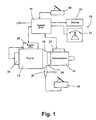
- a driving mode system 10 including an engine 12 interconnected to a transmission 14 through a master clutch 16 and controlled by a system electronic control unit (“ECU") 18. More particularly, the system ECU 18 is electronically connected to an engine ECU 20, which controls the engine 12 through inputs and outputs responsive to driver action and engine performance. Further, the system ECU 18 is connected to the transmission 14 through the transmission operator 22, which controls the transmission 14. The transmission operator 22 receives inputs and outputs for controlling transmission 14 from both driver action and the transmission itself. The driver is apprised of system performance through a display 23, which is interconnected to the system ECU 18 that monitors both the transmission operator 22 and the engine ECU 20. Finally, driver input is accomplished through manipulation of a manually operated selector 24.
- a manually operated selector 24 is accomplished through manipulation of a manually operated selector 24.
- the selector 24 is movable in at least two directions to an activation position, most preferably for up- and down-shifting gear ratios, and includes at least one button for selecting a mode of operation of the transmission 14. The function of selector 24 is explained in greater detail below.
- the transmission operator 22 controls the transmission 14 in response to signals from the system ECU 18.
- the transmission 14 is operated by the transmission operator 22 either automatically, called “automatic transmission mode", or non-automatically, called the manual transmission mode.
- the manual transmission mode is actually a semi-automatic mode.
- the system ECU 18 controls the shifting of gears of the transmission 14 by a signal sent to the transmission operator 22 based on inputs received from the transmission 14, the engine 12, and the driver, among other inputs.
- the driver does not shift gears of the transmission 14. Instead, shifting is controlled by programmed logic in the system ECU 18.
- the gear shift selections are made by the driver.
- the so-called semi-automatic transmission mode permits the driver to make gear shift selections from a range of permissible gears based on a variety of input variables, such as engine performance and vehicle speed.
- the driver determines when to shift gears, and to what gear to shift among the range of permissible gears.
- the listing of permissible gears is determined by the system ECU 18. The driver manually actuates the selector 24 to make the gear shift selection.
- transmission includes both “simple” and “compound” type transmissions.
- a “simple transmission” means a change-speed transmission, wherein the driver may select one of a plurality of single gear reductions.
- a “compound transmission” designates a change-speed transmission having a main transmission portion and an auxiliary transmission portion connected in series whereby the selected gear reduction in the main transmission portion may be compounded by further selected gear reduction in the auxiliary transmission portion.
- Compound transmission includes a “splitter-type compound transmission,” which designates a compound transmission wherein the auxiliary transmission is used to provide various selectable steps for subdivisions of the gear ratio selected in the main transmission portion. In a splitter-type compound transmission, the main transmission section is typically provided with relatively wide steps that are split or subdivided by the auxiliary section.
- Compound transmission also includes a “range-type compound transmission,” which refers to a compound transmission having an auxiliary section with a relatively large step, as compared to the ratio steps of the main transmission ratio into a higher speed gear ratio.
- range-type compound transmission refers to a compound transmission having an auxiliary section with a relatively large step, as compared to the ratio steps of the main transmission ratio into a higher speed gear ratio.
- downshift means shifting from a higher speed gear ratio to a lower speed gear ratio.
- blip designates a temporary increase in the supply of fuel to the engine 12
- the term “dip” means a momentary decrease in supply of fuel to the engine.
- Such terms usually are associated with engine fuel control or engine ECU 20 commanded increases and decreases, respectively, of the supply of fuel to the engine, independent of the driver-selected position of the throttle pedal.
- the present invention is applicable to the control of any type of mechanical change-gear transmission adaptable for providing output signals to and receiving command signals from various electric, electronic, mechanical and/or fluid-operated control and/or sensing devices.
- the control system of the present invention is particularly advantageously applied to a compound transmission of the type having a non-synchronized main transmission section connected in series with at least one auxiliary section of the splitter, range and/or combined splitter/range type.
- Such transmissions are known in the prior art and are described and illustrated in U.S. Pat. Nos. 4,735,109; 4,648,290; 4,754,665; 5,390,561; and 5,816,100.
- the transmission system may be coupled to a power unit through a conventional friction clutch, torque converter, or other convenience power coupling means.
- information concerning the engine is communicated from the engine control ECU 20 to the system ECU 18, which is a processing and memory device. Communication may be over an electronic data link of the type confirming to SAE J1922, SAE J1939, ISO 11898 or any other applicable standard.
- the ECU 18 preferably receives inputs relative to engine speed or transmission input shaft speed from appropriate sensors, transmission output shaft speed from sensor 26, and actuation of selector 24. Transmission output shaft speed is an indication of vehicle ground speed and engine speed is an indication of transmission input shaft speed, and vice versa, especially if clutch 16 is non-slippingly engaged.
- the present invention is equally applicable to systems where the control of the engine is achieved by mechanical methods.
- a suitable throttle position sensor and throttle pedal or "remote fuel control" or “fly-by-wire” system are known in the prior art and are illustrated by U.S. Pat. Nos. 4,250,845; 4,305,359; 4,319,658 and 4,461,254.
- Control logic circuits, sensors and actuators for the transmission system 10, as illustrated schematically in Figure 1 may be as disclosed in aforementioned U.S. Pat. Nos. 4,361,060; 4,648,290; 4,930,081; 4,930,078; and 5,816,100.
- system ECU 18 receives inputs, processes them in accordance with predetermined logic rules, and provides command output signals to pneumatic and/or electrical actuators for control of an input shaft brake 28 for rapid upshifts; engine fuel flow, or alternatively an engine ECU 20, to "blip” or “dip” the engine 12; an exhaust brake 30 to achieve rapid synchronous rotation in preparation for downshift or upshift clutch control via operator 30; and/or ratio shifting via transmission operator 22.
- the processing unit of the system ECU 18 may be of the type illustrated in U.S. Pat. No. 4,595,986 and may incorporate fault detection and tolerance logic of the type illustrated in U.S. Pat. Nos. 4,849,899; 4,899,279; and 4,945,484.
- the transmission operator 22 also may be of the "X-Y" type, as illustrated in U.S. Pat. Nos. 4,873,881 and 4,899,607.
- the system ECU 18 also sends command output signals to the display 23, to be described in greater detail below.
- the driving mode system 10 may additionally comprises a typical foot-operated manual clutch control 34 intended for use only for start-from-rest and/or low speed creeping maneuvering situations.
- the system ECU 18 receives signals indicative of manual clutch control 34 position and of actuation of the vehicle brakes 36.
- the clutch control 34 may be eliminated and the operation of the clutch fully automated under the control of the system ECU 18.
- the driving mode system 10 also includes sources of electric and/or pneumatic power (not illustrated).
- the system ECU 18 may be located in a single box or may in fact be distributed across a number of sites on the vehicle, one of which could be on the transmission housing itself, another of which could be in or near the cab of the vehicle.
- the system ECU 18 is connected to a display 23 of the type shown in Figures 2A and 2B, detects permissible gear shift ranges, indicates a default start mode for the transmission 14, and controls the operating mode of the transmission 14 in response to the driver's selection of cruise control and power take off operations.
- the shifting means is preferably selector 24, but may be buttons or a toggle or any other suitable device or combination of devices.
- Such levers or other devices can be mounted on the vehicle dashboard or fascia, but are more conveniently mounted on the steering column in the same way as other known steering column switches.
- the selector 24 is the type shown in Figure 3, including a lever 40 movable in at least an up and down direction. Further, the lever 40 has a depressible button 42 at the end of the stalk. The lever 40 is movable to up- or downshift gear ratio activation positions, and selects the default starting mode as discussed below. The button 42 is depressible to change between automatic and manual shifting modes.
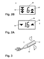
- the display 23 includes upshift indicator section 52, downshift indicator section 54, and currently engaged gear ratio indicator section 50.
- the currently engaged gear ratio display section 50 is presently displaying a "16,” indicating that the vehicle transmission is operating in sixteenth gear.
- the single arrows oppositely disposed adjacent the number "16" indicate the transmission is in automatic mode.
- the upshift display section 52' has three lit downward arrows on one side and two lit upward arrows on opposite sides of the gear ratio display section 50 (showing "6) indicating the maximum number of consecutive downshifts and upshifts permitted according to the sensed input parameters, such as sensed engine or input shaft speed and sensed output shaft speed as processed by the system ECU according to the predetermined logic rules or program.
- the multiple shift arrows indicate the transmission is in manual transmission mode.
- the three lit downward arrows indicate that a single, double or triple downshift is permissible. Accordingly, the driver may select a permissible shift directly to either fifth, fourth or third speed.
- the upshift display section 54' has two lit arrows indicating the maximum number of consecutive upshifts permitted according to the sensed parameters as processed by the predetermined logic or program. In the present situation, the two lit arrows in display section 54' indicate that the transmission may be permissibly upshifted to either seventh or eighth gear.
- the processing unit of the system ECU 18 will not issue command signals to execute a selected but impermissible ratio change.
- the processing unit will execute the closest permissible ratio change to that selected by the driver.
- the system ECU 18 will issue command output signals for a double downshift from sixth gear to fourth gear. Not only is an impermissible ratio change refused, but the driver usually already will have been advised by display 23 that the ratio should never have been attempted or selected.
- Fully automatic transmission systems that include sensors for sensing the throttle openings or positions, vehicle speeds, engine speeds, and the like, and automatically shift the vehicle transmission in response to those inputs, are well known in the prior art.
- Such fully automatic change-gear transmissions include transmissions wherein pressurized fluid is utilized to frictionally engage one or more members to other members or to a ground to achieve a selected gear ratio in automated mechanical transmissions utilizing electronic, hydraulic, and/or pneumatic logic and actuators to engage and disengage mechanical (i.e., positive) clutches to achieve a desired gear ratio. Examples of such transmissions are described in U.S. Patent Nos. 3,961,546; 4,081,065; 4,361,060; 5,050,079; and 5,109,729.
- Semi-automatic mechanical transmission control is also known in the prior art, wherein automated changes between a plurality of gear ratios are selected by the driver. Normally, the driver chooses when to make a particular gear ratio change and whether to select the immediately consecutive ratio up or down or to skip one or more ratios. Examples of such a semi-automatic transmission control can be seen by reference to U.S. Patent Nos. 4,648,290; 4,800,360; 4,930,081; 5,385,515; 5,406,861; and 5,816,100.
- Operating the driving mode system 10 in manual transmission mode means semi-automatic control of the transmission 14 through operator 22 via the system ECU 18. It is called “manual transmission mode” because the driver must manually actuate the selector 24, despite the actual gear change being automated and controlled by the transmission operator 22.
- manual transmission mode or semi-automatic transmission operation
- the driver moves lever 40 to an activation position (e.g., forward for upshifts and rearward for downshifts) from the position illustrated in Figure 3.
- an activation position e.g., forward for upshifts and rearward for downshifts
- the driver will move lever 40 up once (in direction of arrow A) and the lever will then return to the neutral or centered position under bias.
- the throttle is blipped to achieve necessary synchronization during a downshift, or dipped for achieving necessary synchronization during an upshift, all of which is done automatically for the driver by the system ECU 18 in conjunction with engine fuel control or engine ECU 20.
- the reverse mode of operation may be achieved only from the neutral, at-rest position and then is achieved by moving control lever 40 backward (in the direction of arrow B) from the currently engaged neutral position.
- a reverse button (not shown) may be provided, which button must be depressed prior to the processing unit's interpreting a backward movement of the selector 24, when in the neutral position, as a request for reverse operation.
- Other methods of preventing inadvertent operation of reverse gear may be applicable.
- One example is any type of toggle switch or button, which may be located on the shift lever 40.
- Upshifts and/or downshifts involving both the main and auxiliary section are equally simple for the driver to achieve as those involving only the auxiliary section (i.e., a split shift).
- the transmission may be downshifted into lower reverse ratios and upshifted into higher reverse ratios by movement of the control lever 40 backward and forward as indicated.
- a single movement or pulse of the lever 40 is a movement of the lever from the centered or non-displaced/non-selected position to a displaced or selection activation position, in either the upshift or downshift direction, and then the immediate release of the lever, allowing the lever to return to the centered or non-displaced/non-selected position thereof. If the control lever 40 is retained in the displaced or selection position for more than a predetermined period of time (for example, for more than 0.5 to 1.0 seconds, or for more than one or two seconds), an alternative logic controls the resulting function.
- the system ECU 18 allows the driver to program the default mode of operation of the transmission to either the automatic or manual transmission mode. Further, during programming of the default start mode for the transmission, the driver is also able to select the default start gear ratio. The driver is able to change the default mode for the transmission and the default start gear by programming the internal memory of the system ECU 18.
- the driver changes the programmable start options for the transmission 14 and start gear ratio by first deciding that he wishes to change the programmable start options at point 60.
- System 10 determines if the vehicle is stationary at point 62. If the vehicle is not stationary, the start mode programming is not available as shown at point 64. When the vehicle is stationary, the driver selects the gear ratio to be used as the default start gear ratio as shown at point 66. The system ECU confirms that the desired start gear ratio is permissible. If not, the driver must select a new desired start gear ratio that is acceptable to the system ECU 18.
- the driver selects the automatic transmission mode (or Auto Mode on flowchart) at point 68 by depressing the transmission mode switch 42 (or Auto Switch on flowchart) to signal to the system ECU 18 that the automatic mode is selected.
- the display 23 shows the selected transmission mode as described above.
- the driver holds the shift lever 40 in the up position for greater than a pre-selected amount of time as shown at point 70.
- the time should be long enough to prevent accidental engagement of the programming mode.
- holding the shift lever 40 in the up position for greater than three (3) seconds is preferred, while, of course, a shorter or longer time period may be used.
- holding the shift lever 40 in a down position, or forward or rearward position could alternatively be used to enter the programming mode.
- the start mode has been programmed to the internal memory of the system ECU 18 for both the start gear ratio and transmission mode as shown at point 72 of the flow chart of Figure 4.
- the driver simply enters the programming mode by maintaining the vehicle stationary and engaging the transmission mode switch 42 to toggle to the previously non-default mode.
- Next shift lever 40 is maintained in the required activation position for the required amount of time.
- Control systems for automated transmission systems typically include a selectable mode of operation referred to as a "cruise control".
- cruise control When cruise control is activated a selected vehicle speed is automatically maintained without requiring the driver to manually control the fuel throttle or to select or implement transmission shifts.
- a preferred cruise control system is described in U.S. Patent No. 5,053,963.
- the system ECU 18 preferably includes a cruise control system, which is an electronic control system wherein gear selection shift decisions are made and executed upon measured and/or calculated parameters such as current input shaft or engine speed, throttle position, output shaft, or vehicle speed and/or the rate of change thereof and/or expected engine speed or vehicle speed speed and/or the rate of change thereof and/or expected engine speed or vehicle speed at the completion of a potential shift.
- a predetermined program operates shift commands in the cruise control mode, whereby a selected vehicle speed is automatically maintained without requiring driver manipulation of the throttle pedal.
- the cruise control mode of operation is simply an enhanced mode of vehicle operation wherein not only are the gear shift decisions being controlled by the system ECU 18 but so are the throttle decisions.
- the driver selects the cruise control mode of operation, preferably via a selectable button, switch, or toggle on the dashboard fascia or connected to the steering column, the vehicle enters the automatic transmission mode if it is not already in that mode.
- the system ECU 18 must return the vehicle to the proper mode of transmission; that is, the mode of transmission the vehicle was operating in immediately preceding the driver's selection of the cruise control mode of operation.
- power take off is a gear-drive device that is operated from the gear box or from the engine to, for example, raised platforms for loading and unloading pay load, or mixing cement.
- power take off requires that some of the power generated from the engine and its transmission be diverted to the accessory device being operated by the vehicle.
- the vehicle operate in a manual transmission mode during operation of the accessory devices so that, for example, concrete will not deliver faster or slower depending on the system ECU 18 control of the transmission when operating in an automatic mode.
- the driver selects a power take off device for operation, the automatic mode of transmission is disabled until use of the accessory device has been completed. After power take off use is complete, the vehicle reverts back to the transmission mode preceding the use of power take off.
- the control logic of the system ECU 18 in response to the driver's selection of cruise control or power take off modes of operation is illustrated.
- the first step of logic is to determine whether the transmission is operating in an automatic transmission mode as shown at decision point 80. If it is not, when the driver selects cruise control at point 82, the manual transmission mode is temporarily enabled. Then when the driver exits the cruise control mode of operation at point 86, the automatic transmission mode is also terminated at point 88 with the manual transmission mode re-enabled.
- the automatic mode of transmission is maintained as shown at point 92 while the system ECU 18 controls fuel flow in response to all the measured parameters. Then, when the cruise control mode of operation is exited at point 94, the automatic mode of transmission is maintained as shown at point 96 of the flowchart of Figure 5 as it was before cruise control was selected by the driver.
- system ECU 18 disables the automatic transmission mode at point 100, temporarily placing transmission 14 into the manual transmission mode until the driver exits the power take off mode at point 102. Then the automatic transmission mode is re-enabled at point 104. If manual transmission mode has already been selected, power take off operates without interruption or control of the manual transmission mode by the system ECU 18.
Landscapes
- Engineering & Computer Science (AREA)
- General Engineering & Computer Science (AREA)
- Mechanical Engineering (AREA)
- Control Of Transmission Device (AREA)
Claims (9)
- Antriebsmodussystem, das aufweist:wobei die Verarbeitungseinheit (18) sowohl einen Standardstartmodus, der einen Modus aus dem automatischen Getriebemodus und dem manuellen Getriebemodus repräsentiert, sowie eine Standardgangstufe festsetzt, wenn die Wählvorrichtung (24) für eine vorbestimmte Zeitdauer in eine Aktivierungsstellung positioniert ist.ein mehrgängiges mechanisches Geschwindigkeitswechselgetriebe (14);eine manuell betätigte Wählvorrichtung (24) zur Auswahl eines Modus aus einem automatischen Getriebemodus und einem manuellen Getriebemodus und zur Auswahl einer Gangstufe undeine Verarbeitungseinheit (18), die dazu dient, Eingangsgrößen, die den Betrieb der Wählvorrichtung (24) kennzeichnen, entgegenzunehmen und diese Eingangsgrößen entsprechend vorbestimmten logischen Regeln zu verarbeiten, um momentan eingelegte und zulässigerweise einlegbare Gangstufen und Drosselstellungen zu bestimmen, um zwischen einem automatischen und einem manuellen Getriebemodus zu wechseln und um Ausgangsbefehlssignale an nicht vom Fahrzeugführer gesteuerte Betätigungseinrichtungen (28, 20, 30, 22) abzugeben;
- Antriebsmodussystem nach Anspruch 1, wobei die vorbestimmte Zeitdauer in dem Bereich von ungefähr ein bis drei Sekunden liegt.
- Antriebssystem nach Anspruch 1, wobei eine Betätigung der Wählvorrichtung (24) eine Betätigungseinrichtung (22) veranlasst, das Getriebe (14) zwischen dem automatischen und dem manuellen Getriebemodus hin- und her zu schalten.
- Antriebssystem nach Anspruch 3, wobei eine Bewegung der Wählvorrichtung (24) in die Aktivierungsstellung für eine Zeitdauer, die kleiner ist als die vorbestimmte Zeitdauer, für die Verarbeitungseinheit (18) eine Schaltung kennzeichnet.
- Antriebssystem nach Anspruch 1, das ferner eine eine Geschwindigkeitssteuerung enthält und wobei die Verarbeitungseinheit (18) vorübergehend den automatischen Getriebemodus herbeiführt, wenn bei einer Aktivierung der Geschwindigkeitssteuerung durch den Fahrer der gewählte Getriebemodus der manuelle Getriebemodus ist, wobei der manuelle Getriebemodus durch die Verarbeitungseinheit (18) wieder errichtet wird, wenn die Geschwindigkeitssteuerung deaktiviert wird.
- Antriebssystem nach Anspruch 5, wobei der gewählte Getriebemodus der automatische Getriebemodus ist und die Verarbeitungseinheit (18) bei einer Aktivierung und Deaktivierung der Geschwindigkeitssteuerung durch den Fahrer den automatischen Getriebemodus aufrechterhält.
- Antriebssystem nach Anspruch 1, das ferner einen Zapfabtrieb enthält und wobei der gewählte Getriebemodus der automatische Getriebemodus ist, wobei die Verarbeitungseinheit (18) bei einer Aktivierung des Zapfabtriebs den manuellen Getriebemodus herbeiführt, wobei der automatische Getriebemodus durch die Verarbeitungseinheit (18) wieder festgesetzt wird, wenn der Zapfabtrieb deaktiviert wird.
- Antriebssystem nach Anspruch 7, wobei der gewählte Getriebemodus den manuellen Getriebemodus enthält, wobei die Verarbeitungseinheit (18) den manuellen Getriebemodus aufrechterhält, wenn ein Fahrer den Zapfabtrieb aktiviert und deaktiviert.
- Antriebssystem nach Anspruch 1, wobei ein Display (2, 23) den Getriebemodus anzeigt.
Applications Claiming Priority (4)
| Application Number | Priority Date | Filing Date | Title |
|---|---|---|---|
| GB9927924A GB2356676A (en) | 1999-11-26 | 1999-11-26 | Driver programmable transmission mode selection for automatic transmission |
| GB9927924 | 1999-11-26 | ||
| GBGB0025641.2A GB0025641D0 (en) | 1999-11-26 | 2000-10-19 | Driver programmable driving modesystem for automatic transmissions |
| GB0025641 | 2000-10-19 |
Publications (3)
| Publication Number | Publication Date |
|---|---|
| EP1103742A2 EP1103742A2 (de) | 2001-05-30 |
| EP1103742A3 EP1103742A3 (de) | 2003-10-22 |
| EP1103742B1 true EP1103742B1 (de) | 2005-07-20 |
Family
ID=26245176
Family Applications (1)
| Application Number | Title | Priority Date | Filing Date |
|---|---|---|---|
| EP00125640A Expired - Lifetime EP1103742B1 (de) | 1999-11-26 | 2000-11-23 | Fahrerprogrammierbares System der Fahrweise für Automatikgetriebe |
Country Status (5)
| Country | Link |
|---|---|
| US (1) | US6658339B1 (de) |
| EP (1) | EP1103742B1 (de) |
| JP (1) | JP2001187962A (de) |
| BR (1) | BR0005966A (de) |
| DE (1) | DE60021339T2 (de) |
Families Citing this family (23)
| Publication number | Priority date | Publication date | Assignee | Title |
|---|---|---|---|---|
| DE10143735C1 (de) * | 2001-09-06 | 2003-09-11 | Siemens Ag | Verfahren zum Entlasten des Fahrers eines Kraftfahrzeuges und Vorrichtung zur Geschwindigkeitsregelung eines Kraftfahrzeuges |
| DE10202774B4 (de) * | 2002-01-25 | 2012-12-13 | Zf Friedrichshafen Ag | Elektronische Schalteinrichtung für ein Lastschaltgetriebe |
| FR2850724B1 (fr) * | 2003-01-30 | 2006-02-10 | Renault Sa | Procede de selection du mode de fonctionnement d'une boite de vitesses automatisee |
| US6869382B2 (en) * | 2003-05-07 | 2005-03-22 | Daimlerchrysler Corporation | Double-downshift gear strategy for a dual clutch automatic transmission |
| SE525482C2 (sv) * | 2003-07-03 | 2005-03-01 | Volvo Lastvagnar Ab | Förfarande och arrangemang för startväxelval samt ett fordon innefattande detta arrangemang |
| DE10341621B4 (de) * | 2003-09-10 | 2011-07-07 | Preh GmbH, 97616 | Anzeigeinstrument mit einer Ganganzeige |
| JP4573289B2 (ja) | 2003-10-14 | 2010-11-04 | 本田技研工業株式会社 | 自動二輪車 |
| FR2868362B1 (fr) * | 2004-04-06 | 2007-05-18 | Peugeot Citroen Automobiles Sa | Systeme, procede et support d'enregistrement pour reguler la vitesse d'un vehicule automobile |
| US7717823B2 (en) | 2006-11-27 | 2010-05-18 | Zf Friedrichshafen Ag | Method and apparatus for changing shift scheduling modes of automated mechanical transmission |
| US7905812B2 (en) * | 2007-02-02 | 2011-03-15 | Eaton Corporation | PTO brake |
| JP5139520B2 (ja) * | 2007-06-08 | 2013-02-06 | ボルボ ラストバグナー アーベー | 車両における自動的に選択された変速回転数制限を調整する方法 |
| JP4735630B2 (ja) * | 2007-09-28 | 2011-07-27 | トヨタ自動車株式会社 | 自動変速制御装置 |
| US8046140B2 (en) | 2008-01-18 | 2011-10-25 | Eaton Corporation | PTO overspeed protection strategy |
| DE102008018472B3 (de) * | 2008-04-11 | 2009-09-03 | Knorr-Bremse Systeme für Nutzfahrzeuge GmbH | Geschwindigkeitsregelvorrichtung mit Abschaltung zum Gangwechsel |
| SE533343C2 (sv) * | 2009-01-14 | 2010-08-31 | Scania Cv Abp | Anordning och förfarande för transmissionsstyrning för förbättrad manövreringsförmåga |
| US20110043348A1 (en) * | 2009-08-20 | 2011-02-24 | Michael Blackard | Shift Prompt System |
| US8900095B2 (en) * | 2012-05-21 | 2014-12-02 | GM Global Technology Operations LLC | Automatic transmission synchronous gear shift |
| GB2505679B (en) * | 2012-09-06 | 2015-02-18 | Jaguar Land Rover Ltd | Vehicle control system and method |
| CN104455373A (zh) * | 2014-11-13 | 2015-03-25 | 新乡市荣泰电器有限公司 | 一种工程车数字挡位控制器 |
| WO2016109482A1 (en) | 2014-12-29 | 2016-07-07 | Robert Bosch Gmbh | Drive state indicator for an autonomous vehicle |
| JP6330731B2 (ja) * | 2015-06-01 | 2018-05-30 | トヨタ自動車株式会社 | 車両の制御装置 |
| US10364884B2 (en) * | 2017-03-02 | 2019-07-30 | Honda Motor Co., Ltd. | Gear shift control device, a vehicle using the same, and gear shift control method |
| DE102017217323A1 (de) * | 2017-09-28 | 2019-03-28 | Zf Friedrichshafen Ag | Verfahren und Steuergerät zum Betreiben eines Nebenabtriebs |
Family Cites Families (43)
| Publication number | Priority date | Publication date | Assignee | Title |
|---|---|---|---|---|
| US3961546A (en) | 1974-09-17 | 1976-06-08 | Allis-Chalmers Corporation | Digital automatic transmission control |
| US4081065A (en) | 1976-12-23 | 1978-03-28 | Smyth Robert Ralston | Controlled power clutch |
| GB2009968B (en) | 1977-12-07 | 1982-09-08 | Vdo Schindling | Device for controlling the speed of a motor vehicle |
| US4361060A (en) | 1978-01-24 | 1982-11-30 | Smyth Robert Ralston | Mechanical automatic transmission |
| DE2812156C2 (de) | 1978-03-20 | 1983-10-20 | Vdo Adolf Schindling Ag, 6000 Frankfurt | Einrichtung zum Steuern der Stellung eines ein Kraftstoff-Luft-Gemisch beeinflussenden Elements eines Verbrennungsmotors |
| DE2839467C2 (de) | 1978-09-11 | 1985-01-31 | Vdo Adolf Schindling Ag, 6000 Frankfurt | Einrichtung zur Übertragung der Stellung eines die Fahrgeschwindigkeit eines Kraftfahrzeugs steuernden, durch den Fahrzeugführer betätigbaren Steuerelements |
| US4735109A (en) | 1981-07-27 | 1988-04-05 | Eaton Corporation | Semi-blocked transmission |
| DE3131996A1 (de) | 1981-08-13 | 1983-02-24 | Vdo Adolf Schindling Ag, 6000 Frankfurt | Einrichtung zum steuern der stellung eines ein kraftstoff-luft-gemisch beeinflussenden elements |
| US4930081A (en) | 1984-07-23 | 1990-05-29 | Eaton Corporation | Semi-automatic mechanical transmission control and control method |
| GB8418749D0 (en) | 1984-07-23 | 1984-08-30 | Eaton Ltd | Semi-automatic transmission control |
| US4930078A (en) | 1984-07-23 | 1990-05-29 | Eaton Corporation | Semi-automatic mechanical transmission control and control method |
| EP0269772B1 (de) * | 1986-12-05 | 1990-03-21 | Eaton Corporation | Halbautomatische mechanische Getriebesteuerung und Steuerverfahren |
| US4595986A (en) | 1984-10-09 | 1986-06-17 | Eaton Corporation | Method for control of automatic mechanical transmission system utilizing a microprocessor based electronic controller |
| US4754665A (en) | 1986-02-05 | 1988-07-05 | Eaton Corporation | Auxiliary transmission section |
| US4899279A (en) | 1986-04-07 | 1990-02-06 | Eaton Corporation | Method for controlling AMT system including wheel lock-up detection and tolerance |
| US4849899A (en) | 1986-04-07 | 1989-07-18 | Eaton Corporation | Method for controlling AMT system including speed sensor signal fault detection and tolerance |
| GB8725981D0 (en) | 1987-11-05 | 1987-12-09 | Eaton Corp | X-y shifting mechanism |
| US4945484A (en) | 1988-10-13 | 1990-07-31 | Eaton Corporation | Method and control system for controlling AMT system including detection of erroneous gear neutral indication |
| US4873881A (en) | 1989-01-06 | 1989-10-17 | Eaton Corporation | Electrically actuated x-y shifting mechanism |
| JP2827468B2 (ja) | 1990-07-24 | 1998-11-25 | トヨタ自動車株式会社 | 自動変速機の制御装置 |
| US5053963A (en) | 1990-07-30 | 1991-10-01 | Eaton Corporation | AMT cruise control mode shift logic |
| US5050079A (en) | 1990-08-17 | 1991-09-17 | Eaton Corporation | Mode control for mechanical transmission system with semi-automatic shift implementation and manual and automatic shift preselection modes |
| US5109729A (en) | 1991-05-09 | 1992-05-05 | Eaton Corporation | Throttle control fault detection and tolerance method/system |
| GB9218273D0 (en) | 1992-08-27 | 1992-10-14 | Eaton Corp | Scrolling gear ratio selection control system and method |
| GB9218254D0 (en) | 1992-08-27 | 1992-10-14 | Eaton Corp | Start ratio engagement control system and method |
| GB9218274D0 (en) * | 1992-08-27 | 1992-10-14 | Eaton Corp | Start ratio selection control system and method |
| US5506771A (en) * | 1992-08-27 | 1996-04-09 | Eaton Corporation | Start gear ratio control system and method |
| US5390561A (en) | 1993-05-20 | 1995-02-21 | Eaton Corporation | Compound transmission |
| US5445128A (en) * | 1993-08-27 | 1995-08-29 | Detroit Diesel Corporation | Method for engine control |
| US5406861A (en) | 1993-09-22 | 1995-04-18 | Eaton Corporation | Manual modification of automatic mode shift points |
| EP0681121B1 (de) * | 1994-05-05 | 2000-06-21 | Eaton Corporation | Steuerungssystem und -verfahren zur Auswahl des Standardanfahrgetriebeganges |
| US5636120A (en) | 1994-07-15 | 1997-06-03 | Caterpillar Inc. | Direct drive autoshift transmission control |
| US5761628A (en) | 1994-10-27 | 1998-06-02 | Eaton Corporation | Start gear ratio control system and method utilizing the highest allowable start gear ratio |
| GB9422850D0 (en) | 1994-11-11 | 1995-01-04 | Eaton Corp | Semi-automatic mechanical transmission with forced automatic shifting |
| JP3104160B2 (ja) | 1995-02-01 | 2000-10-30 | 本田技研工業株式会社 | 車両用自動変速機の制御装置 |
| GB9505174D0 (en) | 1995-03-15 | 1995-05-03 | Automotive Products Plc | Vehicle transmissions |
| US5845224A (en) * | 1995-10-19 | 1998-12-01 | Case Corporation | Method and apparatus for preselecting gear ratios in a power transmission |
| US5875410A (en) * | 1996-01-12 | 1999-02-23 | Eaton Corporation | Dynamic best gear selection for automated transmission system |
| SE9600454L (sv) * | 1996-02-07 | 1997-04-14 | Scania Cv Ab | Förfarande för korrigering av motormomentet vid växling |
| US5816100A (en) * | 1996-09-17 | 1998-10-06 | Eaton Corporation | Skip shift selection control system and method |
| JPH1148823A (ja) * | 1997-08-04 | 1999-02-23 | Mitsubishi Motors Corp | 車両用定速走行装置 |
| GB9721823D0 (en) * | 1997-10-16 | 1997-12-17 | Eaton Corp | Shift into optimal engine braking control system and method |
| US6151977A (en) * | 1999-02-26 | 2000-11-28 | Freightliner Corporation | Lever assembly for an electronically controllable vehicle transmission |
-
2000
- 2000-11-17 US US09/715,888 patent/US6658339B1/en not_active Expired - Lifetime
- 2000-11-22 JP JP2000356094A patent/JP2001187962A/ja active Pending
- 2000-11-23 DE DE60021339T patent/DE60021339T2/de not_active Expired - Lifetime
- 2000-11-23 EP EP00125640A patent/EP1103742B1/de not_active Expired - Lifetime
- 2000-11-27 BR BR0005966-8A patent/BR0005966A/pt not_active IP Right Cessation
Also Published As
| Publication number | Publication date |
|---|---|
| JP2001187962A (ja) | 2001-07-10 |
| EP1103742A2 (de) | 2001-05-30 |
| BR0005966A (pt) | 2001-07-17 |
| EP1103742A3 (de) | 2003-10-22 |
| US6658339B1 (en) | 2003-12-02 |
| DE60021339D1 (de) | 2005-08-25 |
| DE60021339T2 (de) | 2006-04-20 |
Similar Documents
| Publication | Publication Date | Title |
|---|---|---|
| EP1103742B1 (de) | Fahrerprogrammierbares System der Fahrweise für Automatikgetriebe | |
| US5816100A (en) | Skip shift selection control system and method | |
| EP0584985B1 (de) | Gangauswahlsteuerungseinrichtung und -verfahren mit fortschreitender Anzeige | |
| EP0695893B1 (de) | Steuerung für mechanisches, semi-automatisches Getriebe mit kontinuierlicher Auswahl | |
| EP0898518B1 (de) | Getriebe mit elektischer schaltbetätigung | |
| EP0584986B1 (de) | Anfahrgangauswahlsteuerungseinrichtung und -verfahren | |
| EP0585020B1 (de) | Steuerungssystem und -verfahren des Anfahr-Getriebeganges | |
| EP0681121B1 (de) | Steuerungssystem und -verfahren zur Auswahl des Standardanfahrgetriebeganges | |
| EP1016810B1 (de) | Einrichtung/Verfahren zur Steuerung eines semiautomatischen, mechanischen Getriebes beim rollenden Anfahren | |
| EP0911207B1 (de) | Gangschaltsteuerung und Verfahren für optimale Motorbremsung | |
| EP0769640B1 (de) | Steuerungssystem und Verfahren zur Auswahl des Überspringens von einem Gang | |
| JPH08178035A (ja) | 変速装置の始動比選択制御方法およびその装置 | |
| US5828974A (en) | Reverse engagement interlock control | |
| EP0778429B1 (de) | Steuerung für automatisiertes, mechanisches Getriebe | |
| US5819191A (en) | Adaptive pull-away ratio selection | |
| GB2356676A (en) | Driver programmable transmission mode selection for automatic transmission |
Legal Events
| Date | Code | Title | Description |
|---|---|---|---|
| PUAI | Public reference made under article 153(3) epc to a published international application that has entered the european phase |
Free format text: ORIGINAL CODE: 0009012 |
|
| AK | Designated contracting states |
Kind code of ref document: A2 Designated state(s): AT BE CH CY DE DK ES FI FR GB GR IE IT LI LU MC NL PT SE TR |
|
| AX | Request for extension of the european patent |
Free format text: AL;LT;LV;MK;RO;SI |
|
| PUAL | Search report despatched |
Free format text: ORIGINAL CODE: 0009013 |
|
| AK | Designated contracting states |
Kind code of ref document: A3 Designated state(s): AT BE CH CY DE DK ES FI FR GB GR IE IT LI LU MC NL PT SE TR |
|
| AX | Request for extension of the european patent |
Extension state: AL LT LV MK RO SI |
|
| 17P | Request for examination filed |
Effective date: 20040331 |
|
| 17Q | First examination report despatched |
Effective date: 20040527 |
|
| AKX | Designation fees paid |
Designated state(s): DE FR GB IT SE |
|
| GRAP | Despatch of communication of intention to grant a patent |
Free format text: ORIGINAL CODE: EPIDOSNIGR1 |
|
| GRAS | Grant fee paid |
Free format text: ORIGINAL CODE: EPIDOSNIGR3 |
|
| GRAA | (expected) grant |
Free format text: ORIGINAL CODE: 0009210 |
|
| RIN1 | Information on inventor provided before grant (corrected) |
Inventor name: STASIK, ANTHONY Inventor name: WRIGHT, KEITH Inventor name: FOWLER, PAUL MARTIN |
|
| AK | Designated contracting states |
Kind code of ref document: B1 Designated state(s): DE FR GB IT SE |
|
| REG | Reference to a national code |
Ref country code: GB Ref legal event code: FG4D |
|
| REF | Corresponds to: |
Ref document number: 60021339 Country of ref document: DE Date of ref document: 20050825 Kind code of ref document: P |
|
| REG | Reference to a national code |
Ref country code: SE Ref legal event code: TRGR |
|
| PGFP | Annual fee paid to national office [announced via postgrant information from national office to epo] |
Ref country code: FR Payment date: 20051104 Year of fee payment: 6 |
|
| ET | Fr: translation filed | ||
| PLBE | No opposition filed within time limit |
Free format text: ORIGINAL CODE: 0009261 |
|
| STAA | Information on the status of an ep patent application or granted ep patent |
Free format text: STATUS: NO OPPOSITION FILED WITHIN TIME LIMIT |
|
| 26N | No opposition filed |
Effective date: 20060421 |
|
| PGFP | Annual fee paid to national office [announced via postgrant information from national office to epo] |
Ref country code: IT Payment date: 20061130 Year of fee payment: 7 |
|
| REG | Reference to a national code |
Ref country code: FR Ref legal event code: ST Effective date: 20070731 |
|
| PG25 | Lapsed in a contracting state [announced via postgrant information from national office to epo] |
Ref country code: FR Free format text: LAPSE BECAUSE OF NON-PAYMENT OF DUE FEES Effective date: 20061130 |
|
| PG25 | Lapsed in a contracting state [announced via postgrant information from national office to epo] |
Ref country code: IT Free format text: LAPSE BECAUSE OF NON-PAYMENT OF DUE FEES Effective date: 20071123 |
|
| PGFP | Annual fee paid to national office [announced via postgrant information from national office to epo] |
Ref country code: GB Payment date: 20101022 Year of fee payment: 11 |
|
| PGFP | Annual fee paid to national office [announced via postgrant information from national office to epo] |
Ref country code: SE Payment date: 20111107 Year of fee payment: 12 |
|
| PGFP | Annual fee paid to national office [announced via postgrant information from national office to epo] |
Ref country code: DE Payment date: 20111130 Year of fee payment: 12 |
|
| GBPC | Gb: european patent ceased through non-payment of renewal fee |
Effective date: 20121123 |
|
| PG25 | Lapsed in a contracting state [announced via postgrant information from national office to epo] |
Ref country code: SE Free format text: LAPSE BECAUSE OF NON-PAYMENT OF DUE FEES Effective date: 20121124 |
|
| REG | Reference to a national code |
Ref country code: DE Ref legal event code: R119 Ref document number: 60021339 Country of ref document: DE Effective date: 20130601 |
|
| PG25 | Lapsed in a contracting state [announced via postgrant information from national office to epo] |
Ref country code: DE Free format text: LAPSE BECAUSE OF NON-PAYMENT OF DUE FEES Effective date: 20130601 |
|
| PG25 | Lapsed in a contracting state [announced via postgrant information from national office to epo] |
Ref country code: GB Free format text: LAPSE BECAUSE OF NON-PAYMENT OF DUE FEES Effective date: 20121123 |