EP1103401A2 - Adjustable vehicle roof with a foldable soft top - Google Patents
Adjustable vehicle roof with a foldable soft top Download PDFInfo
- Publication number
- EP1103401A2 EP1103401A2 EP00124189A EP00124189A EP1103401A2 EP 1103401 A2 EP1103401 A2 EP 1103401A2 EP 00124189 A EP00124189 A EP 00124189A EP 00124189 A EP00124189 A EP 00124189A EP 1103401 A2 EP1103401 A2 EP 1103401A2
- Authority
- EP
- European Patent Office
- Prior art keywords
- fabric
- tension
- closed position
- bracket
- bow
- Prior art date
- Legal status (The legal status is an assumption and is not a legal conclusion. Google has not performed a legal analysis and makes no representation as to the accuracy of the status listed.)
- Granted
Links
Images

Classifications
-
- B—PERFORMING OPERATIONS; TRANSPORTING
- B60—VEHICLES IN GENERAL
- B60J—WINDOWS, WINDSCREENS, NON-FIXED ROOFS, DOORS, OR SIMILAR DEVICES FOR VEHICLES; REMOVABLE EXTERNAL PROTECTIVE COVERINGS SPECIALLY ADAPTED FOR VEHICLES
- B60J7/00—Non-fixed roofs; Roofs with movable panels, e.g. rotary sunroofs
- B60J7/08—Non-fixed roofs; Roofs with movable panels, e.g. rotary sunroofs of non-sliding type, i.e. movable or removable roofs or panels, e.g. let-down tops or roofs capable of being easily detached or of assuming a collapsed or inoperative position
- B60J7/12—Non-fixed roofs; Roofs with movable panels, e.g. rotary sunroofs of non-sliding type, i.e. movable or removable roofs or panels, e.g. let-down tops or roofs capable of being easily detached or of assuming a collapsed or inoperative position foldable; Tensioning mechanisms therefor, e.g. struts
- B60J7/1204—Control devices, e.g. for compensating tolerances, for defining movement or end position of top, for tensioning the top or for switching to an emergency mode
-
- B—PERFORMING OPERATIONS; TRANSPORTING
- B60—VEHICLES IN GENERAL
- B60J—WINDOWS, WINDSCREENS, NON-FIXED ROOFS, DOORS, OR SIMILAR DEVICES FOR VEHICLES; REMOVABLE EXTERNAL PROTECTIVE COVERINGS SPECIALLY ADAPTED FOR VEHICLES
- B60J7/00—Non-fixed roofs; Roofs with movable panels, e.g. rotary sunroofs
- B60J7/08—Non-fixed roofs; Roofs with movable panels, e.g. rotary sunroofs of non-sliding type, i.e. movable or removable roofs or panels, e.g. let-down tops or roofs capable of being easily detached or of assuming a collapsed or inoperative position
- B60J7/12—Non-fixed roofs; Roofs with movable panels, e.g. rotary sunroofs of non-sliding type, i.e. movable or removable roofs or panels, e.g. let-down tops or roofs capable of being easily detached or of assuming a collapsed or inoperative position foldable; Tensioning mechanisms therefor, e.g. struts
- B60J7/1226—Soft tops for convertible vehicles
- B60J7/1234—Soft tops for convertible vehicles characterised by arches, e.g. shape or material
- B60J7/1247—Tensioning bow at rear of soft top
Definitions
- the invention relates to an adjustable vehicle roof with a Folding top according to the preamble of claim 1.
- a folding top is known from the publication DE 41 23 516 C1, the one to be assigned a plurality of the top linkage Includes roof frame, bracket and bow, the top linkage with the help of an adjustment kinematics between the Vehicle interior covering closed position and a Storage position releasing vehicle interior is adjustable, in which the folding top in a storage space behind the passenger compartment is filed.
- a fabric retaining bracket is provided, which in the closed position of the convertible top on the one covering the storage space Convertible top compartment lid rests.
- the fabric handle is connected to the cover fabric and acts on the cover fabric with a tension tightening the fabric.
- the Fabric retaining bracket by means of a locking device in the closed position on the vehicle body in its on the top compartment lid held in position.
- the locking device consists of a snap lock that is in the closed position the soft top of the soft top is locked with the convertible top compartment lid.
- closure devices between the fabric bracket and A body-side component is characterized by a high power transmission and accordingly secure locking between the bracket and the vehicle body, giving the possibility is given, the folding top in the closed position a high Imprint tension.
- the closure device comprises a plurality of components that are operated remotely must, the functions of the closure device as well the adjustment kinematics of the vehicle roof are coordinated have to.
- Another problem is that in particular the storage position of the folding top the vehicle-side locking devices step into the field of vision and the overall appearance of the vehicle.
- the dead center position ensures that the Tension bow in the closed position of the vehicle roof.
- the stable However, position can only be maintained as long no impermissibly high on the hinge arrangement in the bow Interfering forces act, for example due to head wind at higher Speeds can arise and in particular through a wear-related play in the joint arrangement is reinforced can be. With this arrangement there is always the risk that the tension bow accidentally in its hinge arrangement buckles.
- the invention is based on the problem of the folding top generic vehicle roofs in the closed position wind and complete waterproof, the shape of the vehicle body should be as free as possible.
- the Fabric retaining bracket which is part of the roof frame and in Closed position of the folding top on the rear body side Component of the vehicle rests with the help of a Fin or tension bow in its on the body component overlying position is held so that on the one hand the fabric tension acting on the fabric support bracket the fabric support bracket not from its position on the body part can solve and on the other hand a sufficiently high material tension can be generated with the help of the fabric bracket.
- the tension bow is supported on the convertible top linkage, so that no additional connections, especially no closure elements, to the vehicle body are needed.
- the Supporting the tension bow on the convertible top linkage is sufficient for one Stabilization of the fabric bracket from, so that on the look interfering closure elements in the vehicle body can be dispensed with without the function of the folding top to affect.
- the convertible top linkage with the Stabilizer bow stabilizing fabric bracket forms vigorously a self-contained system so that the vehicle body no tension forces for tensioning the folding top must record.
- the Tension bow in the closed position in the direction of the vehicle's longitudinal axis extends.
- the top linkage usually unfolds when closing the convertible top in the vehicle's longitudinal direction and at the same time tensions the cover fabric.
- the in this case, the tension bow can be aligned in the longitudinal direction of the vehicle absorb tension forces and the fabric retaining bracket in an optimal manner relieve them or stabilize them.
- the tension bow has a joint arrangement with at least one Joint axis transverse to the longitudinal axis of the vehicle, the joint arrangement is designed as over-center kinematics.
- the clamping bow is in the closed position of the Convertible tops loaded into its over dead center position to safely make sure that the tension bow is not under the fabric tension buckles and inadvertently adjusted in the direction of the storage position becomes.
- the top dead center kinematics allow the Span with a relatively low force in Keep the convertible top in a stable position.
- Tension rope provided that the tension bow in Closed position of the convertible top forces a holding force to one to prevent unintentional snapping back of the clamping bow.
- the tensioning rope is only attached to the roof frame, so that a power cycle limited to the convertible top linkage is realized. That facing away from the fabric handle
- the end of the tensioning cable is attached to a bracket or via a tension spring another component to be assigned to the convertible top linkage held. Via the tension spring, an elastically flexible Behavior of the tension cable can be realized, moreover, is precise Adjustment of those acting on the tension bow in the closed position Holding force possible.
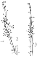
- Fig. 1 is a section of an adjustable vehicle roof shown, which as a folding top with a top linkage 2 is formed, on which a convertible top fabric is stretched is.
- the folding top is between that shown in Fig. 1 Closed position and a storage position adjustable, in which the convertible top linkage including the convertible top fabric is stored in a storage space.
- a transverse Cloth support bracket 3 is provided, which is transverse to the vehicle longitudinal direction extends and the rear section of the upholstery fabric keeps stretched down towards the vehicle body.
- the fabric retaining bracket 3 is part of the top linkage 2 and has only a connection to a bow 4, however no connection to a body-side component, which leads to As a result, the body panel on which the fabric retaining bracket is in the closed position of the vehicle roof, none Tension or holding forces of the convertible top must absorb.
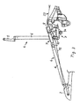
- the Tension bow 4, as in particular also FIGS. 4 and 5 can be seen from a front, with the fabric retaining bracket 3 connected lower mounting bracket 5, one yourself resulting transmission section 6, a joint arrangement 7 and an upper mounting bracket facing the soft top 8, through which the connection to the remaining roof linkage will be produced.
- the upper bracket 8 of the Span 4 is in the region of its end face with a Roof frame 23 (see Fig. 3) articulated, the part of The top linkage of the folding top is.
- the joint arrangement 7 comprises a central, middle section 9, on which two lateral sections 10 and 11 are articulated connect, the hinge axes 12, 13 between the central and the lateral sections 9 and 10, 11 transverse to Vehicle longitudinal direction.
- the tension bow 4 extends itself in the vehicle's longitudinal direction when the Span 4 around the hinge axes 12, 13 is the Clamping bow from the clamping position shown in Fig. 1, which corresponds to the closed position of the folding top, in which Fig. 3 and Fig. 5 shown intermediate position.
- a pull rope 15 is guided on the tension bow 4, which at one end via an attachment point 22 with the Fabric bracket 3 is firmly connected and at its opposite End attached to a bracket 16, which part of the convertible top linkage.
- the bracket 16 is over a kinematics not shown with the roof frame 23rd (Fig. 3) connected.
- the clamping bow 4 that is Traction rope 15 around a pulley 14 on the underside of the central one Joint section 9 of the joint assembly 7 and another Rope pulley 17 performed on the upper bracket 8th is attached, which is held on the side portion 11, which on the side of the clamping bow facing the bracket 16 4 is arranged.
- On the bracket 16 are two more pulleys 18, 19 provided, via which the traction rope deflects direction to its attachment point 20 on the bracket 16.
- the joint arrangement 7 can be Leave the dead center position and around the hinge axes 12 and 13 tilt; this causes the bow 4 to be in its flexion position a, see Fig. 5.
- the transition from the clamping position to Flexion position or from the closed position of the folding top to the storage position is activated by a roof kinematics Actuator triggered.
- the tension spring 21, which is integrated in the pull rope 15, allows in the tensioned position a limited elastic behavior of the pull rope 15.
Abstract
Description
Die Erfindung betrifft ein verstellbares Fahrzeugdach mit einem Faltverdeck gemäß dem Oberbegriff des Anspruches 1.The invention relates to an adjustable vehicle roof with a Folding top according to the preamble of claim 1.
Aus der Druckschrift DE 41 23 516 C1 ist ein Faltverdeck bekannt, das eine Mehrzahl von dem Verdeckgestänge zuzuordnenden Dachrahmen, Bügel sowie Spriegel umfasst, wobei das Verdeckgestänge mit Hilfe einer Verstellkinematik zwischen einer den Fahrzeuginnenraum überdeckenden Schließstellung und einer den Fahrzeuginnenraum freigebenden Ablagestellung verstellbar ist, in welcher das Faltverdeck in einem Stauraum hinter der Fahrgastzelle abgelegt ist. Um sicher zu stellen, dass der Verdeck-Bezugstoff des Faltverdecks in Schließstellung unter Spannung steht und am Verdeckgestänge aufliegt, ist im rückwärtigen Bereich des Fahrzeugdaches ein Stoffhaltebügel vorgesehen, welcher in Schließstellung des Verdecks auf dem den Stauraum überdeckenden Verdeckkastendeckel aufliegt. Der Stoffhaltebügel ist mit dem Verdeck-Bezugstoff verbunden und beaufschlagt den Bezugstoff mit einer den Stoff straffenden Spannung. Um zu verhindern, das der Stoffhaltebügel als Reaktion der Stoffspannung in Schließstellung vom Verdeckkastendeckel abhebt, wird der Stoffhaltebügel mittels einer Verschlussvorrichtung in Schließstellung an der Fahrzeugkarosserie in seiner auf dem Verdeckkastendeckel aufliegenden Position gehalten. Die Verschlussvorrichtung besteht aus einem Schnappverschluss, der in Schließstellung des Verdecks eine Verriegelung des Stoffhaltebügels mit dem Verdeckkastendeckel bewirkt. Um bei der Überführungsbewegung des Faltverdecks von Schließ- in Ablagestellung den Stoffhaltebügel aufstellen zu können und den Verdeckkastendeckel öffnen zu können, kann der Schnappverschluss mit Hilfe eines elektromotorischen Stellantriebs entriegelt werden.A folding top is known from the publication DE 41 23 516 C1, the one to be assigned a plurality of the top linkage Includes roof frame, bracket and bow, the top linkage with the help of an adjustment kinematics between the Vehicle interior covering closed position and a Storage position releasing vehicle interior is adjustable, in which the folding top in a storage space behind the passenger compartment is filed. To ensure that the soft top fabric the folding top in the closed position under tension stands and rests on the convertible top linkage, is in the rear area of the vehicle roof, a fabric retaining bracket is provided, which in the closed position of the convertible top on the one covering the storage space Convertible top compartment lid rests. The fabric handle is connected to the cover fabric and acts on the cover fabric with a tension tightening the fabric. To prevent, that of the fabric retaining bracket in response to the fabric tension in the closed position from the top compartment lid, the Fabric retaining bracket by means of a locking device in the closed position on the vehicle body in its on the top compartment lid held in position. The locking device consists of a snap lock that is in the closed position the soft top of the soft top is locked with the convertible top compartment lid. To the transfer movement of the folding top from the closed to the storage position To be able to set up fabric retaining brackets and the top compartment lid To be able to open the snap lock with the help of a electromotive actuator can be unlocked.
Derartige Verschlussvorrichtungen zwischen Stoffhaltebügel und einem karosserieseitigen Bauteil zeichnen sich zwar durch eine hohe Kraftübertragung und dementsprechend sichere Verriegelung zwischen Bügel und Fahrzeugkarosserie aus, wodurch die Möglichkeit gegeben ist, dem Faltverdeck in Schließstellung eine hohe Spannung aufzuprägen. Die Verschlussvorrichtung umfasst aber eine Mehrzahl von Bauteilen, die ferngesteuert betätigt werden müssen, wobei die Funktionen der Verschlussvorrichtung sowie der Verstellkinematik des Fahrzeugverdecks koordiniert werden müssen. Ein weiteres Problem besteht darin, das insbesondere in der Ablagestellung des Faltverdecks die fahrzeugseitigen Verschlussvorrichtungen in den Sichtbereich treten und das Gesamterscheinungsbild des Fahrzeuges beeinträchtigen können.Such closure devices between the fabric bracket and A body-side component is characterized by a high power transmission and accordingly secure locking between the bracket and the vehicle body, giving the possibility is given, the folding top in the closed position a high Imprint tension. However, the closure device comprises a plurality of components that are operated remotely must, the functions of the closure device as well the adjustment kinematics of the vehicle roof are coordinated have to. Another problem is that in particular the storage position of the folding top the vehicle-side locking devices step into the field of vision and the overall appearance of the vehicle.
Aus der gattungsbildenden Druckschrift DE 297 12 706 U1 ist ein Faltverdeck bekannt, dessen Verdeck-Bezugsstoff mittels eines Stoffhaltebügels in Schließstellung des Verdecks unter Spannung gehalten wird, wobei der Stoffhaltebügel von einem Spannspriegel beaufschlagt wird, in den eine Gelenkanordnung eingebracht ist, die in Schließstellung des Verdecks eine Übertotpunktlage einnimmt.From the generic document DE 297 12 706 U1 is a Folded top known, the top fabric by means of a Fabric retaining bracket in the closed position of the convertible top under tension is held, the fabric holding bracket by a tension bow is applied, in which a joint arrangement is introduced is in the closed position of the convertible top dead center occupies.
Die Übertotpunktlage sorgt zwar für eine stabile Stellung des Spannspriegels in Schließposition des Fahrzeugdaches. Die stabile Stellung kann jedoch nur aufrecht erhalten werden, solange auf die Gelenkanordnung im Spannspriegel keine unzulässig hohen Störkräfte wirken, die beispielsweise durch Fahrtwind bei höheren Geschwindigkeiten entstehen können und insbesondere durch ein verschleißbedingtes Spiel in der Gelenkanordnung verstärkt werden können. Bei dieser Anordnung besteht daher immer die Gefahr, dass der Spannspriegel versehentlich in seiner Gelenkanordnung einknickt.The dead center position ensures that the Tension bow in the closed position of the vehicle roof. The stable However, position can only be maintained as long no impermissibly high on the hinge arrangement in the bow Interfering forces act, for example due to head wind at higher Speeds can arise and in particular through a wear-related play in the joint arrangement is reinforced can be. With this arrangement there is always the risk that the tension bow accidentally in its hinge arrangement buckles.
Der Erfindung liegt das Problem zu Grunde, das Faltverdeck des gattungsgemäßen Fahrzeugdaches in Schließstellung wind- und wasserdicht abzuschließen, wobei die Form der Fahrzeugkarosserie möglichst frei gestaltbar sein soll.The invention is based on the problem of the folding top generic vehicle roofs in the closed position wind and complete waterproof, the shape of the vehicle body should be as free as possible.
Dieses Problem wird erfindungsgemäß mit den Merkmalen des Anspruches 1 gelöst.This problem is solved according to the invention with the features of the claim 1 solved.
Gemäß dem neuartigen Fahrzeugdach ist vorgesehen, dass der Stoffhaltebügel, welcher Teil des Verdeckgestänges ist und in Schließstellung des Faltverdecks auf dem rückwärtigen karosserieseitigen Bauteil des Fahrzeugs aufliegt, mit Hilfe eines Finnen- bzw. Spannspriegels in seiner auf dem Karosserie-Bauteil aufliegenden Position gehalten wird, so dass einerseits die auf den Stoffhaltebügel wirkende Stoffspannung den Stoffhaltebügel nicht von seiner Position auf dem Karosserie-Bauteil zu lösen vermag und andererseits eine ausreichend hohe Stoffspannung mit Hilfe des Stoffhaltebügels erzeugt werden kann. Der Spannspriegel stützt sich hierbei am Verdeckgestänge ab, so dass keine zusätzlichen Verbindungen, insbesondere keine Verschlusselemente, zur Fahrzeugkarosserie benötigt werden. Die Abstützung des Spannspriegels am Verdeckgestänge reicht für eine Stabilisierung des Stoffhaltebügels aus, so dass auf die Optik beeinträchtigende Verschlusselemente in der Fahrzeugkarosserie verzichtet werden kann, ohne die Funktion des Faltverdecks zu beeinträchtigen. Das Verdeckgestänge mit dem den Stoffhaltebügel stabilisierenden Spannspriegel bildet kräftemäßig ein in sich geschlossenes System, so dass die Fahrzeugkarosserie keine Spannkräfte für die Spannung des Faltverdecks aufnehmen muss.According to the novel vehicle roof, it is provided that the Fabric retaining bracket, which is part of the roof frame and in Closed position of the folding top on the rear body side Component of the vehicle rests with the help of a Fin or tension bow in its on the body component overlying position is held so that on the one hand the fabric tension acting on the fabric support bracket the fabric support bracket not from its position on the body part can solve and on the other hand a sufficiently high material tension can be generated with the help of the fabric bracket. The tension bow is supported on the convertible top linkage, so that no additional connections, especially no closure elements, to the vehicle body are needed. The Supporting the tension bow on the convertible top linkage is sufficient for one Stabilization of the fabric bracket from, so that on the look interfering closure elements in the vehicle body can be dispensed with without the function of the folding top to affect. The convertible top linkage with the Stabilizer bow stabilizing fabric bracket forms vigorously a self-contained system so that the vehicle body no tension forces for tensioning the folding top must record.
Gemäß einer vorteilhaften Ausführung ist vorgesehen, dass der Spannspriegel sich in Schließstellung in Richtung des Fahrzeuglängsachse erstreckt. Das Verdeckgestänge entfaltet sich üblicherweise beim Schließen des Verdecks in Fahrzeuglängsrichtung und spannt hierbei zugleich den Bezugstoff des Verdecks. Der in Fahrzeuglängsrichtung ausgerichtete Spannspriegel kann hierbei in optimaler Weise Spannkräfte aufnehmen und den Stoffhaltebügel von diesen entlasten bzw. diesen stabilisieren.According to an advantageous embodiment it is provided that the Tension bow in the closed position in the direction of the vehicle's longitudinal axis extends. The top linkage usually unfolds when closing the convertible top in the vehicle's longitudinal direction and at the same time tensions the cover fabric. The in In this case, the tension bow can be aligned in the longitudinal direction of the vehicle absorb tension forces and the fabric retaining bracket in an optimal manner relieve them or stabilize them.
Der Spannspriegel weist eine Gelenkanordnung mit zumindest einer Gelenkachse quer zur Fahrzeuglängsachse auf, wobei die Gelenkanordnung als Übertotpunkt-Kinematik ausgebildet ist. Der Spannspriegel wird in dieser Ausführung in Schließstellung des Verdecks in seine Übertotpunkt-Stellung belastet, um sicher zu stellen, dass der Spannspriegel unter der Stoffspannung nicht einknickt und versehentlich in Richtung der Ablagestellung verstellt wird. Die Übertotpunkt-Kinematik erlaubt es, den Spannspriegel mit einer verhältnismäßig geringen Kraft in Schließstellung des Verdecks in einer stabilen Position zu halten.The tension bow has a joint arrangement with at least one Joint axis transverse to the longitudinal axis of the vehicle, the joint arrangement is designed as over-center kinematics. The In this version, the clamping bow is in the closed position of the Convertible tops loaded into its over dead center position to safely make sure that the tension bow is not under the fabric tension buckles and inadvertently adjusted in the direction of the storage position becomes. The top dead center kinematics allow the Span with a relatively low force in Keep the convertible top in a stable position.
Weiterhin ist ein den Spannspriegel in Schließstellung beaufschlagendes Spannseil vorgesehen, das dem Spannspriegel in Schließstellung des Verdecks eine Haltekraft aufzwingt, um ein unbeabsichtigtes Zurückschnappen des Spannspriegels zu verhindern. Um Krafteinleitungen in die Fahrzeugkarosserie zu vermeiden, ist das Spannseil ausschließlich am Verdeckgestänge befestigt, so dass ein auf das Verdeckgestänge beschränkter Kräftekreislauf realisiert wird. Das dem Stoffhaltebügel abgewandte Ende des Spannseils wird über eine Zugfeder an einem Bügel oder einem sonstigen, dem Verdeckgestänge zuzuordnenden Bauteil gehalten. Über die Zugfeder kann ein elastisch nachgiebiges Verhalten des Spannseils realisiert werden, zudem ist eine präzise Einstellung der den Spannspriegel in Schließstellung beaufschlagenden Haltekraft möglich. Furthermore, one acts on the tension bow in the closed position Tension rope provided that the tension bow in Closed position of the convertible top forces a holding force to one to prevent unintentional snapping back of the clamping bow. In order to avoid the introduction of force into the vehicle body, the tensioning rope is only attached to the roof frame, so that a power cycle limited to the convertible top linkage is realized. That facing away from the fabric handle The end of the tensioning cable is attached to a bracket or via a tension spring another component to be assigned to the convertible top linkage held. Via the tension spring, an elastically flexible Behavior of the tension cable can be realized, moreover, is precise Adjustment of those acting on the tension bow in the closed position Holding force possible.
Weitere Vorteile und zweckmäßige Ausführungsformen sind den weiteren Ansprüchen, der Figurenbeschreibung und den Zeichnungen zu entnehmen. Es zeigen:
- Fig. 1
- eine Seitenansicht auf einen in Spannstellung dargestellten Spannspriegel in einem Fahrzeugdach, der einen Stoffhaltebügel in Schließstellung beaufschlagt, wobei der Spannspriegel über ein Zugseil mit einem Bügel des Verdeckgestänges verbunden ist.
- Fig. 2
- den Spannspriegel in einer Ansicht von oben,
- Fig. 3
- eine Fig. 1 entsprechende Ansicht mit einer Darstellung eines Dachrahmens, der Teil des Verdeckgestänges ist und an dem der Spannspriegel drehbar gelagert ist,
- Fig. 4
- eine perspektivische Darstellung des Spannspriegels in einer der Verdeck-Schließstellung entsprechenden Streckstellung,
- Fig. 5
- eine perspektivische Darstellung des Spannspriegels in einer der Verdeck-Ablagestellung entsprechenden Zwischenstellung.
- Fig. 1
- a side view of a tension bow shown in the tensioned position in a vehicle roof, which acts on a fabric retaining bracket in the closed position, wherein the tension bow is connected via a traction cable with a bracket of the folding top linkage.
- Fig. 2
- the tension bow in a view from above,
- Fig. 3
- 1 corresponding view with a representation of a roof frame which is part of the roof linkage and on which the tension bow is rotatably mounted,
- Fig. 4
- 2 shows a perspective view of the tensioning bow in a stretched position corresponding to the folding top closing position,
- Fig. 5
- a perspective view of the clamping bow in an intermediate position corresponding to the top storage position.
Bei den in den Fig. 1 bis 5 dargestellten Ausführungsbeispielen sind gleiche Bauteile mit gleichen Bezugszeichen versehen.In the embodiments shown in FIGS. 1 to 5 the same components are provided with the same reference numerals.
In Fig. 1 ist ein Ausschnitt aus einem verstellbaren Fahrzeugdach
dargestellt, welches als Faltverdeck mit einem Verdeckgestänge
2 ausgebildet ist, auf dem ein Verdeck-Bezugstoff aufgespannt
ist. Das Faltverdeck ist zwischen der in Fig. 1 dargestellten
Schließstellung und einer Ablagestellung verstellbar,
in der das Verdeckgestänge einschließlich dem Verdeckbezugstoff
in einem Stauraum abgelegt ist. Um sicher zu stellen, dass in
Schließstellung der Verdeck-Bezugstoff eine ausreichende Stoffspannung
aufweist, welche gewährleistet, dass der Verdeckbezugstoff
fest am Verdeckgestänge anliegt und ein wind- und wasserdichter
Abschluss zur Fahrzeugkarosserie gegeben ist, ist im
rückwärtigen Bereich des Faltverdecks ein querverlaufender
Stoffhaltebügel 3 vorgesehen, der sich quer zur Fahrzeuglängsrichtung
erstreckt und den hinteren Abschnitt des Bezugstoffs
nach unten in Richtung der Fahrzeugkarosserie gespannt hält.
Der Stoffhaltebügel 3 ist Teil des Verdeckgestänges 2 und weist
lediglich eine Anbindung an einen Spannspriegel 4 auf, jedoch
keine Anbindung zu einem karosserieseitigen Bauteil, was zur
Folge hat, das die Karosserieverkleidung, auf der der Stoffhaltebügel
in Schließstellung des Fahrzeugverdecks aufliegt, keine
Spann- oder Haltekräfte des Verdecks aufnehmen muss. Der
Spannspriegel 4 besteht, wie insbesondere auch den Fig. 4 und 5
zu entnehmen ist, aus einem stirnseitigen, mit dem Stoffhaltebügel
3 verbundenen unteren Befestigungsbügel 5, einem sich
daraus anschließenden Übertragungsabschnitt 6, einer Gelenkanordnung
7 sowie einem oberen, dem Verdeck zugewandtem Befestigungsbügel
8, über den die Verbindung zum übrigen Verdeckgestänge
hergestellt wird. Der obere Befestigungsbügel 8 des
Spannspriegels 4 ist im Bereich seiner Stirnseite mit einem
Dachrahmen 23 (siehe Fig. 3) gelenkig verbunden, der Teil des
Verdeckgestänges des Faltverdeckes ist.In Fig. 1 is a section of an adjustable vehicle roof
shown, which as a folding top with a
Die Gelenkanordnung 7 umfasst einen zentralen, mittleren Abschnitt
9, an den sich zwei seitliche Abschnitte 10 und 11 gelenkig
anschließen, wobei die Gelenkachsen 12, 13 zwischen dem
zentralen und den seitlichen Abschnitten 9 bzw. 10, 11 quer zur
Fahrzeuglängsrichtung verlaufen. Der Spannspriegel 4 erstreckt
sich in Fahrzeuglängsrichtung, bei einer Bewegung des
Spannspriegels 4 um die Gelenkachsen 12, 13 wird der
Spannspriegel aus der in Fig. 1 dargestellten Spannstellung,
die der Schließstellung des Faltverdecks entspricht, in die in
Fig. 3 und Fig. 5 dargestellte Zwischenstellung versetzt.
Weiterhin ist am Spannspriegel 4 ein Zugseil 15 geführt, welches
an einem Ende über einen Befestigungspunkt 22 mit dem
Stoffhaltebügel 3 fest verbunden ist und an seinem gegenüberliegenden
Ende an einem Bügel 16 befestigt ist, welcher Teil
des Verdeckgestänges des Faltverdeckes ist. Der Bügel 16 ist über
eine nichtdargestellte Kinematik mit dem Dachrahmen 23
(Fig. 3) verbunden. Im Bereich des Spannspriegels 4 ist das
Zugseil 15 um eine Seilrolle 14 auf der Unterseite des zentralen
Gelenkabschnitts 9 der Gelenkanordnung 7 und um eine weitere
Seilrolle 17 geführt, die an dem oberen Befestigungsbügel 8
befestigt ist, der an dem seitlichen Abschnitt 11 gehalten ist,
welcher auf der dem Bügel 16 zugewandten Seite des Spannspriegels
4 angeordnet ist. Am Bügel 16 sind zwei weitere Seilrollen
18, 19 vorgesehen, über die das Zugseil eine Richtungsumlenkung
zu seinem Befestigungspunkt 20 am Bügel 16 erfährt. Unmittelbar
vor dem Befestigungspunkt 20 ist in das Zugseil 15 eine Zugfeder
21 integriert.The
In Schließstellung des Faltverdecks wird der Stoffhaltebügel 3
über den Spannspriegel 4 nach unten gedrückt. Der Spannspriegel
4 wird hierbei über das gespannte Zugseil 15 in seiner Spanstellung
gehalten. Um eine versehentliches und unbeabsichtigtes
Verschwenken um die Gelenkachsen 12 und 13 zu verhindern, was
ein Zuklappen des Spannspriegels 4 in die in Fig. 5 gezeigte
Stellung zur Folge hätte, ist die Gelenkanordnung 7 als Übertotpunkt-Kinematik
ausgebildet, die in Schließstellung des
Spannspriegels durch das Zugseil 15 in ihre Übertotpunkt-Stellung
beaufschlagt wird. Die auf der Unterseite des zentralen
Gelenkabschnitts 9 gehaltene Seilrolle 14 weist quer zur
Längsachse des Spannspriegels 4 einen Abstand sowohl zum Befestigungspunkt
22 des Spannseils am Stoffhaltebügel 3 als auch
zur oberen Seilrolle 17 am oberen Befestigungsbügel 8 auf. Auf
Grund dieses Querabstandes sowie der gegenläufigen Umlenkung um
die Seilrollen 14 und 17 entsteht bei einer Spannung des Zugseils
15 eine Kraftkomponente quer zur Längsachse des Spannriegels
4 auf die seitlichen Gelenkabschnitte 10, 11, die diese
Gelenkabschnitte in die Übertotpunkt-Stellung beaufschlagt.In the closed position of the folding top, the
Wird die Seilspannung gelöst, so kann die Gelenkanordnung 7 ihre
Übertotpunkt-Stellung verlassen und um die Gelenkachsen 12
und 13 kippen; hierdurch nimmt der Spannspriegel 4 seine Beugestellung
ein, siehe Fig. 5. Der Übergang von Spannstellung zu
Beugestellung bzw. von Schließstellung des Faltverdecks zur Ablagestellung
wird durch ein die Verdeckkinematik beaufschlagendes
Stellglied ausgelöst.If the rope tension is released, the
Die Zugfeder 21, die in das Zugseil 15 integriert ist, erlaubt
in Spannstellung ein begrenzt elastisches Verhalten des Zugseils
15.The
Claims (3)
dadurch gekennzeichnet,
characterized,
dadurch gekennzeichnet,
dass der Spannspriegel (4) sich in Schließstellung in Richtung der Fahrzeuglängsachse erstreckt.Vehicle roof according to claim 1,
characterized,
that the tension bow (4) extends in the closed position in the direction of the vehicle longitudinal axis.
dadurch gekennzeichnet,
dass das dem Stoffhaltebügel (3) abgewandte Ende des Spannseils um eine Umlenkrolle geführt ist, die an einem Bügel (16) des Verdeckgestänges (2) gehalten ist.Vehicle roof according to claim 1 or 2,
characterized,
that the end of the tensioning cable facing away from the fabric holding bracket (3) is guided around a deflection roller which is held on a bracket (16) of the folding top linkage (2).
Applications Claiming Priority (2)
| Application Number | Priority Date | Filing Date | Title |
|---|---|---|---|
| DE19957012 | 1999-11-26 | ||
| DE19957012A DE19957012B4 (en) | 1999-11-26 | 1999-11-26 | Adjustable vehicle roof with a folding top |
Publications (3)
| Publication Number | Publication Date |
|---|---|
| EP1103401A2 true EP1103401A2 (en) | 2001-05-30 |
| EP1103401A3 EP1103401A3 (en) | 2002-07-17 |
| EP1103401B1 EP1103401B1 (en) | 2004-03-31 |
Family
ID=7930464
Family Applications (1)
| Application Number | Title | Priority Date | Filing Date |
|---|---|---|---|
| EP00124189A Expired - Lifetime EP1103401B1 (en) | 1999-11-26 | 2000-11-08 | Adjustable vehicle roof with a foldable soft top |
Country Status (3)
| Country | Link |
|---|---|
| US (1) | US6328372B1 (en) |
| EP (1) | EP1103401B1 (en) |
| DE (2) | DE19957012B4 (en) |
Families Citing this family (17)
| Publication number | Priority date | Publication date | Assignee | Title |
|---|---|---|---|---|
| DE10216891C1 (en) | 2002-04-17 | 2003-11-20 | Porsche Ag | Motor vehicle with a hood |
| US6820917B2 (en) | 2002-09-18 | 2004-11-23 | Asc Incorporated | Vehicle convertible roof |
| US6695386B1 (en) | 2002-09-18 | 2004-02-24 | Asc Incorporated | Vehicle retractable hardtop roof |
| DE10258052C5 (en) | 2002-12-11 | 2008-06-12 | Magna Car Top Systems Gmbh | Adjustable vehicle roof for convertible vehicles |
| FR2848921B1 (en) * | 2002-12-20 | 2005-02-04 | France Design | DISPOSITION OF THE RETRACTABLE ROOF OF A MOTOR VEHICLE |
| US7014247B2 (en) | 2003-03-03 | 2006-03-21 | Asc Incorporated | Hardtop convertible |
| US6695385B1 (en) | 2003-03-31 | 2004-02-24 | Asc Incorporated | Vehicle convertible roof |
| DE10349848A1 (en) * | 2003-10-25 | 2005-06-02 | Wilhelm Karmann Gmbh | Convertible car |
| DE10349849A1 (en) * | 2003-10-25 | 2005-06-16 | Wilhelm Karmann Gmbh | Convertible car |
| JP4690385B2 (en) * | 2004-02-27 | 2011-06-01 | ツェーテーエス ファーツォイク ダッハジステーム ゲーエムベーハー | Spring clip for convertible top with side tension cable |
| US7104587B2 (en) * | 2004-04-30 | 2006-09-12 | Asc Incorporated | Joint locking device for a convertible roof system |
| US6957842B1 (en) * | 2004-04-30 | 2005-10-25 | Asc Incorporated | Convertible roof bow tensioning apparatus |
| US7246841B2 (en) * | 2004-09-23 | 2007-07-24 | Asc Incorporated | In-folding convertible roof |
| DE102004047910A1 (en) * | 2004-09-29 | 2006-04-20 | PARAT Automotive Schönenbach GmbH + Co. KG | Device for clamping or for displacing at least one top surface element |
| US7690716B2 (en) * | 2006-05-23 | 2010-04-06 | Specialty Vehicle Acquisition Corp. | Convertible roof |
| US7857373B2 (en) * | 2007-05-15 | 2010-12-28 | Specialty Vehicle Acquisition Corp. | Automotive vehicle convertible roof system |
| US8025328B2 (en) * | 2008-03-07 | 2011-09-27 | Specialty Vehicle Acquisition Corp. | Automotive vehicle convertible roof system |
Citations (6)
| Publication number | Priority date | Publication date | Assignee | Title |
|---|---|---|---|---|
| EP0303018A2 (en) * | 1987-08-08 | 1989-02-15 | Bayerische Motoren Werke Aktiengesellschaft, Patentabteilung AJ-3 | Folding top for a convertible or similar motor vehicle |
| US5026110A (en) * | 1989-05-03 | 1991-06-25 | Ed Scharwachter Gmbh & Co. Kg | Convertible top for motor vehicles |
| EP0733505A1 (en) * | 1995-03-21 | 1996-09-25 | Applied Power Inc. | Motor vehicle with foldable roof, and foldable roof for such a motor vehicle |
| US5772275A (en) * | 1992-09-04 | 1998-06-30 | Asc Incorporated | Apparatus and method for securing a convertible roof to an automobile vehicle |
| US5816644A (en) * | 1995-06-22 | 1998-10-06 | Wilhelm Karmann Gmbh | Folding top for a convertible |
| DE19820711A1 (en) * | 1998-05-11 | 1999-11-18 | Daimler Chrysler Ag | Damping fitting for front structure of cabriolet roof resting on top of windscreen frame |
Family Cites Families (24)
| Publication number | Priority date | Publication date | Assignee | Title |
|---|---|---|---|---|
| DE1154726B (en) * | 1959-03-05 | 1963-09-19 | Daimler Benz Ag | Bracket of the two side parts (hood lugs) located behind the side windows of folding tops for motor vehicles (convertibles) |
| DE3012411A1 (en) | 1980-03-29 | 1981-10-08 | Hackforth GmbH & Co KG, 4690 Herne | ELASTIC SHAFT COUPLING, IN PARTICULAR JOINT SHAFT ADJUSTMENT COUPLING |
| US4693509A (en) * | 1986-03-28 | 1987-09-15 | General Motors Corporation | Convertible top |
| US4747635A (en) * | 1987-03-02 | 1988-05-31 | Cars & Concepts, Inc. | Vehicle convertible top having sail flap tensioner |
| DE3718093A1 (en) * | 1987-05-29 | 1988-12-08 | Porsche Ag | TENSIONING DEVICE FOR THE CANOPY COVER OF A MOTOR VEHICLE |
| DE3903680C1 (en) * | 1989-02-08 | 1990-04-12 | Daimler-Benz Aktiengesellschaft, 7000 Stuttgart, De | |
| DE3907227C1 (en) * | 1989-03-07 | 1990-05-23 | Daimler-Benz Aktiengesellschaft, 7000 Stuttgart, De | |
| DE4031270C1 (en) * | 1990-10-04 | 1991-10-31 | Parat-Werk Schoenenbach Gmbh + Co Kg, 5630 Remscheid, De | Retractable roof for motor vehicle - has inner cover of canopy moved by traction cord with spring |
| DE4123516C1 (en) * | 1991-07-16 | 1992-07-09 | Mercedes-Benz Aktiengesellschaft, 7000 Stuttgart, De | |
| DE4441666C1 (en) * | 1994-11-23 | 1995-12-14 | Porsche Ag | Collapsible roof for vehicle |
| DE29516415U1 (en) * | 1995-10-17 | 1995-12-07 | Karmann Gmbh W | Cabriolet vehicle |
| US5620226A (en) * | 1995-12-07 | 1997-04-15 | Dura Convertible Systems, Inc. | Simplified automated top operator |
| DE19613356C2 (en) * | 1996-04-03 | 1998-04-16 | Karosserie Baur Gmbh | Kinematic hood for cars |
| DE19616255C1 (en) * | 1996-04-24 | 1997-05-07 | Porsche Ag | Folding roof with stirrup adjustable in closed position for motor vehicle |
| DE19622953C1 (en) * | 1996-06-07 | 1997-08-07 | Porsche Ag | Folding soft top for vehicle |
| DE19637005C1 (en) * | 1996-09-12 | 1997-12-18 | Daimler Benz Ag | Plate covering for front area of frame opening of hood box |
| US6022064A (en) * | 1997-06-30 | 2000-02-08 | Robbins Auto Top Company, Inc. | Partitioned cable sleeve for automobile convertible tops |
| DE29712706U1 (en) * | 1997-07-18 | 1998-02-26 | Karmann Gmbh W | Cabriolet vehicle with a convertible top that can be lowered into a convertible top compartment |
| DE19734671C2 (en) * | 1997-08-11 | 1999-10-21 | Daimler Chrysler Ag | Folding roof arrangement for a motor vehicle with a folding cover |
| US6042174A (en) * | 1997-08-22 | 2000-03-28 | Asc Incorporated | Latching and control apparatus for an automotive vehicle convertible roof |
| DE19754189C2 (en) * | 1997-12-06 | 1999-09-30 | Porsche Ag | Folding hood for a vehicle, in particular a passenger car |
| DE29806543U1 (en) * | 1998-04-09 | 1999-09-02 | Edscha Cabrio Verdecksys Gmbh | Folding top for convertible vehicles |
| EP0974480B1 (en) * | 1998-07-20 | 2001-05-23 | Dura Convertible Systems GmbH | Folding top system for motor vehicle |
| DE29909513U1 (en) * | 1999-05-31 | 1999-09-02 | Edscha Cabrio Verdecksys Gmbh | Folding roof for passenger cars |
-
1999
- 1999-11-26 DE DE19957012A patent/DE19957012B4/en not_active Expired - Lifetime
-
2000
- 2000-11-08 EP EP00124189A patent/EP1103401B1/en not_active Expired - Lifetime
- 2000-11-08 DE DE50005886T patent/DE50005886D1/en not_active Expired - Lifetime
-
2001
- 2001-05-25 US US09/721,905 patent/US6328372B1/en not_active Expired - Lifetime
Patent Citations (6)
| Publication number | Priority date | Publication date | Assignee | Title |
|---|---|---|---|---|
| EP0303018A2 (en) * | 1987-08-08 | 1989-02-15 | Bayerische Motoren Werke Aktiengesellschaft, Patentabteilung AJ-3 | Folding top for a convertible or similar motor vehicle |
| US5026110A (en) * | 1989-05-03 | 1991-06-25 | Ed Scharwachter Gmbh & Co. Kg | Convertible top for motor vehicles |
| US5772275A (en) * | 1992-09-04 | 1998-06-30 | Asc Incorporated | Apparatus and method for securing a convertible roof to an automobile vehicle |
| EP0733505A1 (en) * | 1995-03-21 | 1996-09-25 | Applied Power Inc. | Motor vehicle with foldable roof, and foldable roof for such a motor vehicle |
| US5816644A (en) * | 1995-06-22 | 1998-10-06 | Wilhelm Karmann Gmbh | Folding top for a convertible |
| DE19820711A1 (en) * | 1998-05-11 | 1999-11-18 | Daimler Chrysler Ag | Damping fitting for front structure of cabriolet roof resting on top of windscreen frame |
Also Published As
| Publication number | Publication date |
|---|---|
| DE50005886D1 (en) | 2004-05-06 |
| US6328372B1 (en) | 2001-12-11 |
| DE19957012B4 (en) | 2004-08-26 |
| EP1103401A3 (en) | 2002-07-17 |
| EP1103401B1 (en) | 2004-03-31 |
| DE19957012A1 (en) | 2001-06-13 |
Similar Documents
| Publication | Publication Date | Title |
|---|---|---|
| EP1103401B1 (en) | Adjustable vehicle roof with a foldable soft top | |
| EP0530134B1 (en) | Foldable top for vehicles | |
| DE102009007331B4 (en) | Roof arrangement for a convertible and convertible with such a roof arrangement | |
| DE202005017077U1 (en) | Sliding door arrangement for a motor vehicle | |
| EP1744921B1 (en) | Hood for a cabriolet vehicle | |
| DE3201895A1 (en) | FOLDING COVER FOR A MOTOR VEHICLE, IN PARTICULAR PERSONAL VEHICLES | |
| DE19942427B4 (en) | Folding hood for a convertible | |
| DE10131886C2 (en) | Device for separating a convertible top storage space of a convertible | |
| DE4130180C1 (en) | ||
| DE4126114C1 (en) | ||
| DE10258052B4 (en) | Adjustable vehicle roof for convertible vehicles | |
| EP1314601A1 (en) | Openable vehicle roof with a folding top | |
| EP0763444B1 (en) | Rear seat for automotive vehicles, particularly for passenger cars | |
| DE10247724B3 (en) | Cabriolet vehicle with the convertible top compartment accommodating the convertible top | |
| DE102005026055A1 (en) | Roof system for soft top convertibles has two side frames which support roof, each of which is made up of three sections connected by pivots and can be folded down when roof is not in use | |
| EP1354742B1 (en) | Motor vehicle with an openable soft top | |
| DE102007045780A1 (en) | Convertible soft top device for motor vehicle i.e. cabriolet vehicle, has convertible top elements arranged on side of flexible convertible soft top cover and turned away from vehicle interior in closed state of cover | |
| DE4210550C2 (en) | Folding hood for vehicles | |
| DE19936099B4 (en) | Locking mechanism for a folding top | |
| DE10140433A1 (en) | Soft top for convertible has control lever driven by one of roof arches | |
| EP1897725B1 (en) | Tensioning device for the rear section of a soft top and convertible | |
| DE19943771C1 (en) | Automobile folding sunroof panel has tensioning cords for securing side edges of sunroof panel in its closed position attached to spring-loaded tensioning blocks | |
| DE202005014328U1 (en) | Cabriolet vehicle has run-out guide edge for flexible roof cover in mounting bar at distance from accommodation space to enable flexible cover to be moved into different angular deployment positions relative to mounting bar | |
| DE19943766C1 (en) | Automobile folding sunroof panel has transverse support struts for sunroof fabric pressed against automobile roof in closed position of sunroof via tensioning bands | |
| EP1560726B1 (en) | Cabriolet vehicle comprising a retractable top |
Legal Events
| Date | Code | Title | Description |
|---|---|---|---|
| PUAI | Public reference made under article 153(3) epc to a published international application that has entered the european phase |
Free format text: ORIGINAL CODE: 0009012 |
|
| AK | Designated contracting states |
Kind code of ref document: A2 Designated state(s): AT BE CH CY DE DK ES FI FR GB GR IE IT LI LU MC NL PT SE TR |
|
| AX | Request for extension of the european patent |
Free format text: AL;LT;LV;MK;RO;SI |
|
| PUAL | Search report despatched |
Free format text: ORIGINAL CODE: 0009013 |
|
| AK | Designated contracting states |
Kind code of ref document: A3 Designated state(s): AT BE CH CY DE DK ES FI FR GB GR IE IT LI LU MC NL PT SE TR |
|
| AX | Request for extension of the european patent |
Free format text: AL;LT;LV;MK;RO;SI |
|
| RIC1 | Information provided on ipc code assigned before grant |
Free format text: 7B 60J 7/12 A, 7B 60J 7/185 B |
|
| 17P | Request for examination filed |
Effective date: 20020808 |
|
| AKX | Designation fees paid |
Designated state(s): DE IT |
|
| GRAP | Despatch of communication of intention to grant a patent |
Free format text: ORIGINAL CODE: EPIDOSNIGR1 |
|
| GRAS | Grant fee paid |
Free format text: ORIGINAL CODE: EPIDOSNIGR3 |
|
| GRAA | (expected) grant |
Free format text: ORIGINAL CODE: 0009210 |
|
| AK | Designated contracting states |
Kind code of ref document: B1 Designated state(s): DE IT |
|
| REG | Reference to a national code |
Ref country code: IE Ref legal event code: FG4D Free format text: GERMAN |
|
| REF | Corresponds to: |
Ref document number: 50005886 Country of ref document: DE Date of ref document: 20040506 Kind code of ref document: P |
|
| REG | Reference to a national code |
Ref country code: IE Ref legal event code: FD4D |
|
| PLBE | No opposition filed within time limit |
Free format text: ORIGINAL CODE: 0009261 |
|
| STAA | Information on the status of an ep patent application or granted ep patent |
Free format text: STATUS: NO OPPOSITION FILED WITHIN TIME LIMIT |
|
| 26N | No opposition filed |
Effective date: 20050104 |
|
| PGFP | Annual fee paid to national office [announced via postgrant information from national office to epo] |
Ref country code: DE Payment date: 20131121 Year of fee payment: 14 |
|
| PGFP | Annual fee paid to national office [announced via postgrant information from national office to epo] |
Ref country code: IT Payment date: 20131126 Year of fee payment: 14 |
|
| REG | Reference to a national code |
Ref country code: DE Ref legal event code: R119 Ref document number: 50005886 Country of ref document: DE |
|
| PG25 | Lapsed in a contracting state [announced via postgrant information from national office to epo] |
Ref country code: DE Free format text: LAPSE BECAUSE OF NON-PAYMENT OF DUE FEES Effective date: 20150602 |
|
| PG25 | Lapsed in a contracting state [announced via postgrant information from national office to epo] |
Ref country code: IT Free format text: LAPSE BECAUSE OF NON-PAYMENT OF DUE FEES Effective date: 20141108 |