EP1102525A1 - Printed wiring board and method for producing the same - Google Patents
Printed wiring board and method for producing the same Download PDFInfo
- Publication number
- EP1102525A1 EP1102525A1 EP99929729A EP99929729A EP1102525A1 EP 1102525 A1 EP1102525 A1 EP 1102525A1 EP 99929729 A EP99929729 A EP 99929729A EP 99929729 A EP99929729 A EP 99929729A EP 1102525 A1 EP1102525 A1 EP 1102525A1
- Authority
- EP
- European Patent Office
- Prior art keywords
- metal foil
- via hole
- blind via
- surface metal
- pattern
- Prior art date
- Legal status (The legal status is an assumption and is not a legal conclusion. Google has not performed a legal analysis and makes no representation as to the accuracy of the status listed.)
- Granted
Links
- 238000004519 manufacturing process Methods 0.000 title claims abstract description 24
- 239000002184 metal Substances 0.000 claims abstract description 105
- 229910052751 metal Inorganic materials 0.000 claims abstract description 105
- 239000011888 foil Substances 0.000 claims abstract description 94
- 239000000758 substrate Substances 0.000 claims abstract description 37
- 230000015572 biosynthetic process Effects 0.000 claims abstract description 25
- 238000005530 etching Methods 0.000 claims abstract description 18
- 238000007747 plating Methods 0.000 claims abstract description 16
- 238000000034 method Methods 0.000 claims abstract description 11
- 239000011248 coating agent Substances 0.000 claims description 12
- 238000000576 coating method Methods 0.000 claims description 12
- 239000004020 conductor Substances 0.000 claims description 10
- 229910000679 solder Inorganic materials 0.000 description 8
- RYGMFSIKBFXOCR-UHFFFAOYSA-N Copper Chemical compound [Cu] RYGMFSIKBFXOCR-UHFFFAOYSA-N 0.000 description 4
- 239000000463 material Substances 0.000 description 4
- 239000000126 substance Substances 0.000 description 4
- 239000011521 glass Substances 0.000 description 3
- 229920005989 resin Polymers 0.000 description 3
- 239000011347 resin Substances 0.000 description 3
- 239000004593 Epoxy Substances 0.000 description 2
- PXHVJJICTQNCMI-UHFFFAOYSA-N Nickel Chemical compound [Ni] PXHVJJICTQNCMI-UHFFFAOYSA-N 0.000 description 2
- 229910052802 copper Inorganic materials 0.000 description 2
- 239000010949 copper Substances 0.000 description 2
- 239000011889 copper foil Substances 0.000 description 2
- 238000009713 electroplating Methods 0.000 description 2
- 239000000945 filler Substances 0.000 description 2
- 239000004642 Polyimide Substances 0.000 description 1
- 230000007423 decrease Effects 0.000 description 1
- 238000010586 diagram Methods 0.000 description 1
- 230000000694 effects Effects 0.000 description 1
- 239000003822 epoxy resin Substances 0.000 description 1
- 239000004744 fabric Substances 0.000 description 1
- PCHJSUWPFVWCPO-UHFFFAOYSA-N gold Chemical compound [Au] PCHJSUWPFVWCPO-UHFFFAOYSA-N 0.000 description 1
- 229910052737 gold Inorganic materials 0.000 description 1
- 239000010931 gold Substances 0.000 description 1
- 230000010354 integration Effects 0.000 description 1
- 229910052759 nickel Inorganic materials 0.000 description 1
- 229920000647 polyepoxide Polymers 0.000 description 1
- 229920001721 polyimide Polymers 0.000 description 1
- 238000005488 sandblasting Methods 0.000 description 1
- 238000004381 surface treatment Methods 0.000 description 1
Images


Classifications
-
- H—ELECTRICITY
- H05—ELECTRIC TECHNIQUES NOT OTHERWISE PROVIDED FOR
- H05K—PRINTED CIRCUITS; CASINGS OR CONSTRUCTIONAL DETAILS OF ELECTRIC APPARATUS; MANUFACTURE OF ASSEMBLAGES OF ELECTRICAL COMPONENTS
- H05K1/00—Printed circuits
- H05K1/02—Details
- H05K1/0213—Electrical arrangements not otherwise provided for
- H05K1/0263—High current adaptations, e.g. printed high current conductors or using auxiliary non-printed means; Fine and coarse circuit patterns on one circuit board
- H05K1/0265—High current adaptations, e.g. printed high current conductors or using auxiliary non-printed means; Fine and coarse circuit patterns on one circuit board characterized by the lay-out of or details of the printed conductors, e.g. reinforced conductors, redundant conductors, conductors having different cross-sections
-
- H—ELECTRICITY
- H05—ELECTRIC TECHNIQUES NOT OTHERWISE PROVIDED FOR
- H05K—PRINTED CIRCUITS; CASINGS OR CONSTRUCTIONAL DETAILS OF ELECTRIC APPARATUS; MANUFACTURE OF ASSEMBLAGES OF ELECTRICAL COMPONENTS
- H05K3/00—Apparatus or processes for manufacturing printed circuits
- H05K3/40—Forming printed elements for providing electric connections to or between printed circuits
- H05K3/42—Plated through-holes or plated via connections
-
- H—ELECTRICITY
- H01—ELECTRIC ELEMENTS
- H01L—SEMICONDUCTOR DEVICES NOT COVERED BY CLASS H10
- H01L21/00—Processes or apparatus adapted for the manufacture or treatment of semiconductor or solid state devices or of parts thereof
- H01L21/02—Manufacture or treatment of semiconductor devices or of parts thereof
- H01L21/04—Manufacture or treatment of semiconductor devices or of parts thereof the devices having potential barriers, e.g. a PN junction, depletion layer or carrier concentration layer
- H01L21/48—Manufacture or treatment of parts, e.g. containers, prior to assembly of the devices, using processes not provided for in a single one of the subgroups H01L21/06 - H01L21/326
- H01L21/4814—Conductive parts
- H01L21/4846—Leads on or in insulating or insulated substrates, e.g. metallisation
- H01L21/486—Via connections through the substrate with or without pins
-
- H—ELECTRICITY
- H05—ELECTRIC TECHNIQUES NOT OTHERWISE PROVIDED FOR
- H05K—PRINTED CIRCUITS; CASINGS OR CONSTRUCTIONAL DETAILS OF ELECTRIC APPARATUS; MANUFACTURE OF ASSEMBLAGES OF ELECTRICAL COMPONENTS
- H05K1/00—Printed circuits
- H05K1/02—Details
- H05K1/11—Printed elements for providing electric connections to or between printed circuits
- H05K1/111—Pads for surface mounting, e.g. lay-out
- H05K1/112—Pads for surface mounting, e.g. lay-out directly combined with via connections
- H05K1/113—Via provided in pad; Pad over filled via
-
- H—ELECTRICITY
- H05—ELECTRIC TECHNIQUES NOT OTHERWISE PROVIDED FOR
- H05K—PRINTED CIRCUITS; CASINGS OR CONSTRUCTIONAL DETAILS OF ELECTRIC APPARATUS; MANUFACTURE OF ASSEMBLAGES OF ELECTRICAL COMPONENTS
- H05K1/00—Printed circuits
- H05K1/02—Details
- H05K1/11—Printed elements for providing electric connections to or between printed circuits
- H05K1/111—Pads for surface mounting, e.g. lay-out
- H05K1/112—Pads for surface mounting, e.g. lay-out directly combined with via connections
- H05K1/114—Pad being close to via, but not surrounding the via
-
- H—ELECTRICITY
- H05—ELECTRIC TECHNIQUES NOT OTHERWISE PROVIDED FOR
- H05K—PRINTED CIRCUITS; CASINGS OR CONSTRUCTIONAL DETAILS OF ELECTRIC APPARATUS; MANUFACTURE OF ASSEMBLAGES OF ELECTRICAL COMPONENTS
- H05K3/00—Apparatus or processes for manufacturing printed circuits
- H05K3/0011—Working of insulating substrates or insulating layers
- H05K3/0017—Etching of the substrate by chemical or physical means
- H05K3/0026—Etching of the substrate by chemical or physical means by laser ablation
- H05K3/0032—Etching of the substrate by chemical or physical means by laser ablation of organic insulating material
- H05K3/0035—Etching of the substrate by chemical or physical means by laser ablation of organic insulating material of blind holes, i.e. having a metal layer at the bottom
-
- H—ELECTRICITY
- H05—ELECTRIC TECHNIQUES NOT OTHERWISE PROVIDED FOR
- H05K—PRINTED CIRCUITS; CASINGS OR CONSTRUCTIONAL DETAILS OF ELECTRIC APPARATUS; MANUFACTURE OF ASSEMBLAGES OF ELECTRICAL COMPONENTS
- H05K3/00—Apparatus or processes for manufacturing printed circuits
- H05K3/40—Forming printed elements for providing electric connections to or between printed circuits
- H05K3/42—Plated through-holes or plated via connections
- H05K3/421—Blind plated via connections
-
- H—ELECTRICITY
- H01—ELECTRIC ELEMENTS
- H01L—SEMICONDUCTOR DEVICES NOT COVERED BY CLASS H10
- H01L2224/00—Indexing scheme for arrangements for connecting or disconnecting semiconductor or solid-state bodies and methods related thereto as covered by H01L24/00
- H01L2224/01—Means for bonding being attached to, or being formed on, the surface to be connected, e.g. chip-to-package, die-attach, "first-level" interconnects; Manufacturing methods related thereto
- H01L2224/10—Bump connectors; Manufacturing methods related thereto
- H01L2224/15—Structure, shape, material or disposition of the bump connectors after the connecting process
- H01L2224/16—Structure, shape, material or disposition of the bump connectors after the connecting process of an individual bump connector
-
- H—ELECTRICITY
- H01—ELECTRIC ELEMENTS
- H01L—SEMICONDUCTOR DEVICES NOT COVERED BY CLASS H10
- H01L2924/00—Indexing scheme for arrangements or methods for connecting or disconnecting semiconductor or solid-state bodies as covered by H01L24/00
- H01L2924/01—Chemical elements
- H01L2924/01078—Platinum [Pt]
-
- H—ELECTRICITY
- H01—ELECTRIC ELEMENTS
- H01L—SEMICONDUCTOR DEVICES NOT COVERED BY CLASS H10
- H01L2924/00—Indexing scheme for arrangements or methods for connecting or disconnecting semiconductor or solid-state bodies as covered by H01L24/00
- H01L2924/01—Chemical elements
- H01L2924/01079—Gold [Au]
-
- H—ELECTRICITY
- H01—ELECTRIC ELEMENTS
- H01L—SEMICONDUCTOR DEVICES NOT COVERED BY CLASS H10
- H01L2924/00—Indexing scheme for arrangements or methods for connecting or disconnecting semiconductor or solid-state bodies as covered by H01L24/00
- H01L2924/15—Details of package parts other than the semiconductor or other solid state devices to be connected
- H01L2924/151—Die mounting substrate
- H01L2924/153—Connection portion
- H01L2924/1531—Connection portion the connection portion being formed only on the surface of the substrate opposite to the die mounting surface
- H01L2924/15311—Connection portion the connection portion being formed only on the surface of the substrate opposite to the die mounting surface being a ball array, e.g. BGA
-
- H—ELECTRICITY
- H05—ELECTRIC TECHNIQUES NOT OTHERWISE PROVIDED FOR
- H05K—PRINTED CIRCUITS; CASINGS OR CONSTRUCTIONAL DETAILS OF ELECTRIC APPARATUS; MANUFACTURE OF ASSEMBLAGES OF ELECTRICAL COMPONENTS
- H05K2201/00—Indexing scheme relating to printed circuits covered by H05K1/00
- H05K2201/03—Conductive materials
- H05K2201/0332—Structure of the conductor
- H05K2201/0335—Layered conductors or foils
- H05K2201/0352—Differences between the conductors of different layers of a multilayer
-
- H—ELECTRICITY
- H05—ELECTRIC TECHNIQUES NOT OTHERWISE PROVIDED FOR
- H05K—PRINTED CIRCUITS; CASINGS OR CONSTRUCTIONAL DETAILS OF ELECTRIC APPARATUS; MANUFACTURE OF ASSEMBLAGES OF ELECTRICAL COMPONENTS
- H05K2201/00—Indexing scheme relating to printed circuits covered by H05K1/00
- H05K2201/03—Conductive materials
- H05K2201/0332—Structure of the conductor
- H05K2201/0388—Other aspects of conductors
- H05K2201/0394—Conductor crossing over a hole in the substrate or a gap between two separate substrate parts
-
- H—ELECTRICITY
- H05—ELECTRIC TECHNIQUES NOT OTHERWISE PROVIDED FOR
- H05K—PRINTED CIRCUITS; CASINGS OR CONSTRUCTIONAL DETAILS OF ELECTRIC APPARATUS; MANUFACTURE OF ASSEMBLAGES OF ELECTRICAL COMPONENTS
- H05K2201/00—Indexing scheme relating to printed circuits covered by H05K1/00
- H05K2201/09—Shape and layout
- H05K2201/09209—Shape and layout details of conductors
- H05K2201/09372—Pads and lands
- H05K2201/09472—Recessed pad for surface mounting; Recessed electrode of component
-
- H—ELECTRICITY
- H05—ELECTRIC TECHNIQUES NOT OTHERWISE PROVIDED FOR
- H05K—PRINTED CIRCUITS; CASINGS OR CONSTRUCTIONAL DETAILS OF ELECTRIC APPARATUS; MANUFACTURE OF ASSEMBLAGES OF ELECTRICAL COMPONENTS
- H05K2201/00—Indexing scheme relating to printed circuits covered by H05K1/00
- H05K2201/09—Shape and layout
- H05K2201/09209—Shape and layout details of conductors
- H05K2201/095—Conductive through-holes or vias
- H05K2201/09509—Blind vias, i.e. vias having one side closed
- H05K2201/09527—Inverse blind vias, i.e. bottoms outwards in multilayer PCB; Blind vias in centre of PCB having opposed bottoms
-
- H—ELECTRICITY
- H05—ELECTRIC TECHNIQUES NOT OTHERWISE PROVIDED FOR
- H05K—PRINTED CIRCUITS; CASINGS OR CONSTRUCTIONAL DETAILS OF ELECTRIC APPARATUS; MANUFACTURE OF ASSEMBLAGES OF ELECTRICAL COMPONENTS
- H05K2201/00—Indexing scheme relating to printed circuits covered by H05K1/00
- H05K2201/09—Shape and layout
- H05K2201/09209—Shape and layout details of conductors
- H05K2201/09654—Shape and layout details of conductors covering at least two types of conductors provided for in H05K2201/09218 - H05K2201/095
- H05K2201/09736—Varying thickness of a single conductor; Conductors in the same plane having different thicknesses
-
- H—ELECTRICITY
- H05—ELECTRIC TECHNIQUES NOT OTHERWISE PROVIDED FOR
- H05K—PRINTED CIRCUITS; CASINGS OR CONSTRUCTIONAL DETAILS OF ELECTRIC APPARATUS; MANUFACTURE OF ASSEMBLAGES OF ELECTRICAL COMPONENTS
- H05K2201/00—Indexing scheme relating to printed circuits covered by H05K1/00
- H05K2201/10—Details of components or other objects attached to or integrated in a printed circuit board
- H05K2201/10613—Details of electrical connections of non-printed components, e.g. special leads
- H05K2201/10621—Components characterised by their electrical contacts
- H05K2201/10674—Flip chip
-
- H—ELECTRICITY
- H05—ELECTRIC TECHNIQUES NOT OTHERWISE PROVIDED FOR
- H05K—PRINTED CIRCUITS; CASINGS OR CONSTRUCTIONAL DETAILS OF ELECTRIC APPARATUS; MANUFACTURE OF ASSEMBLAGES OF ELECTRICAL COMPONENTS
- H05K2203/00—Indexing scheme relating to apparatus or processes for manufacturing printed circuits covered by H05K3/00
- H05K2203/03—Metal processing
- H05K2203/0353—Making conductive layer thin, e.g. by etching
-
- H—ELECTRICITY
- H05—ELECTRIC TECHNIQUES NOT OTHERWISE PROVIDED FOR
- H05K—PRINTED CIRCUITS; CASINGS OR CONSTRUCTIONAL DETAILS OF ELECTRIC APPARATUS; MANUFACTURE OF ASSEMBLAGES OF ELECTRICAL COMPONENTS
- H05K2203/00—Indexing scheme relating to apparatus or processes for manufacturing printed circuits covered by H05K3/00
- H05K2203/05—Patterning and lithography; Masks; Details of resist
- H05K2203/0548—Masks
- H05K2203/0554—Metal used as mask for etching vias, e.g. by laser ablation
-
- H—ELECTRICITY
- H05—ELECTRIC TECHNIQUES NOT OTHERWISE PROVIDED FOR
- H05K—PRINTED CIRCUITS; CASINGS OR CONSTRUCTIONAL DETAILS OF ELECTRIC APPARATUS; MANUFACTURE OF ASSEMBLAGES OF ELECTRICAL COMPONENTS
- H05K3/00—Apparatus or processes for manufacturing printed circuits
- H05K3/02—Apparatus or processes for manufacturing printed circuits in which the conductive material is applied to the surface of the insulating support and is thereafter removed from such areas of the surface which are not intended for current conducting or shielding
- H05K3/027—Apparatus or processes for manufacturing printed circuits in which the conductive material is applied to the surface of the insulating support and is thereafter removed from such areas of the surface which are not intended for current conducting or shielding the conductive material being removed by irradiation, e.g. by photons, alpha or beta particles
-
- H—ELECTRICITY
- H05—ELECTRIC TECHNIQUES NOT OTHERWISE PROVIDED FOR
- H05K—PRINTED CIRCUITS; CASINGS OR CONSTRUCTIONAL DETAILS OF ELECTRIC APPARATUS; MANUFACTURE OF ASSEMBLAGES OF ELECTRICAL COMPONENTS
- H05K3/00—Apparatus or processes for manufacturing printed circuits
- H05K3/46—Manufacturing multilayer circuits
- H05K3/4644—Manufacturing multilayer circuits by building the multilayer layer by layer, i.e. build-up multilayer circuits
- H05K3/4652—Adding a circuit layer by laminating a metal foil or a preformed metal foil pattern
-
- Y—GENERAL TAGGING OF NEW TECHNOLOGICAL DEVELOPMENTS; GENERAL TAGGING OF CROSS-SECTIONAL TECHNOLOGIES SPANNING OVER SEVERAL SECTIONS OF THE IPC; TECHNICAL SUBJECTS COVERED BY FORMER USPC CROSS-REFERENCE ART COLLECTIONS [XRACs] AND DIGESTS
- Y10—TECHNICAL SUBJECTS COVERED BY FORMER USPC
- Y10T—TECHNICAL SUBJECTS COVERED BY FORMER US CLASSIFICATION
- Y10T29/00—Metal working
- Y10T29/49—Method of mechanical manufacture
- Y10T29/49002—Electrical device making
- Y10T29/49117—Conductor or circuit manufacturing
- Y10T29/49124—On flat or curved insulated base, e.g., printed circuit, etc.
- Y10T29/49155—Manufacturing circuit on or in base
- Y10T29/49156—Manufacturing circuit on or in base with selective destruction of conductive paths
-
- Y—GENERAL TAGGING OF NEW TECHNOLOGICAL DEVELOPMENTS; GENERAL TAGGING OF CROSS-SECTIONAL TECHNOLOGIES SPANNING OVER SEVERAL SECTIONS OF THE IPC; TECHNICAL SUBJECTS COVERED BY FORMER USPC CROSS-REFERENCE ART COLLECTIONS [XRACs] AND DIGESTS
- Y10—TECHNICAL SUBJECTS COVERED BY FORMER USPC
- Y10T—TECHNICAL SUBJECTS COVERED BY FORMER US CLASSIFICATION
- Y10T29/00—Metal working
- Y10T29/49—Method of mechanical manufacture
- Y10T29/49002—Electrical device making
- Y10T29/49117—Conductor or circuit manufacturing
- Y10T29/49124—On flat or curved insulated base, e.g., printed circuit, etc.
- Y10T29/49155—Manufacturing circuit on or in base
- Y10T29/49165—Manufacturing circuit on or in base by forming conductive walled aperture in base
- Y10T29/49167—Manufacturing circuit on or in base by forming conductive walled aperture in base with deforming of conductive path
Definitions
- the present invention relates to a printed circuit board and a method of manufacturing same, and more particularly, to the formation of a pattern and the formation of a blind via hole on a printed circuit board.
- a printed circuit board includes an insulative substrate having an upper surface on which an upper surface pattern is formed and a lower surface on which a lower surface pattern is formed, and blind via holes for electrically connecting the upper and lower surface patterns. Due to the recent trend of greater integration, a blind via hole is formed by a laser so that it has a microscopic diameter.
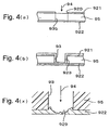
- an upper surface and a lower surface of an insulative substrate 95 are respectively coated by upper surface and lower surface metal foils 921, 922.
- An opening 920 is formed in the upper surface metal foil 921 in correspondence with a blind via hole formation portion 935, and a laser 94 is emitted toward the opening 920.
- the laser 94 forms an opening in the insulative substrate 95 at a position corresponding to the blind via hole formation portion 935 and forms a blind via hole 93 that extends to the lower surface metal foil 922.
- chemical plating or electroplating is performed to form a metal plating film 923 on the wall of the blind via hole 93.
- the thickness of the metal foil may be reduced.
- the laser 94 may inflict damage 929 on the lower surface metal foil 922.
- a first embodiment according to the present invention proposes a method for manufacturing a printed circuit board.
- the method includes the steps of coating a lower surface and an upper surface of an insulative substrate, respectively, with a lower surface metal foil and an upper surface metal foil, the thickness of which is less than that of the lower surface metal foil, forming an opening in the upper surface metal foil at a portion corresponding to a blind via hole formation portion of the insulative substrate, forming a blind via hole, the bottom of which is the lower surface metal foil, by emitting a laser against the blind via hole formation portion through the opening, applying a conductor to the blind via hole, and forming an upper surface pattern and a lower surface pattern by respectively etching the upper surface metal foil and the lower surface metal foil.
- the thickness of the upper surface metal foil is less than the thickness of the lower surface metal foil. This facilitates etching of the upper surface pattern, and the thickness of the lower surface metal foil is such that the lower surface metal foil is prevented from being damaged by the emission of a laser during formation of the blind via hole. Accordingly, the upper pattern is easily formed through etching, damage to the lower surface pattern due to the laser emission is prevented, and a conductor is applied to the blind via hole in a satisfactory state.
- etching be performed on the upper surface metal foil to remove part of the upper surface metal foil. In this manner, by performing etching in a single step, the formation of the thin upper surface metal foil is facilitated.
- a metal plating film may further be applied to the surface of the lower metal foil.
- the thickness of the upper surface pattern be 2 to 12 ⁇ m. When thinner than 2 ⁇ m, the strength of the upper pattern may be insufficient. When thicker than 12 ⁇ m, etching may be difficult during the formation of the upper surface pattern.
- the thickness of the lower surface pattern be 15 to 25 ⁇ m.
- the lower surface pattern, which defines the bottom of the blind via hole may be damaged by the laser emission. Further, there is no benefit to making the thickness greater than 25 ⁇ m.
- a conductor to the via hole
- chemical plating and electroplating may be performed to form a metal plating film on the wall of the via hole or the interior of the via hole may be filled with a conductive material, such as solder.
- a conductive material such as solder.
- other methods may be employed to apply a conductor.
- a resin material such as epoxy, polyimide, and bismaleimidetriazine, or a filler-containing multiple resin substrate made of these resin materials in addition to glass cloth and glass filler may be used as the insulative substrate.
- the upper surface metal foil and the lower surface metal foil may, for example, both be made of copper foil, although other materials may be used.
- the upper surface pattern and the lower surface pattern are formed after applying a conductor to the blind via hole.
- the upper surface pattern and the lower surface pattern may be formed before forming the blind via hole.
- a method for manufacturing a printed circuit board includes the steps of coating a lower surface and an upper surface of an insulative substrate respectively with a lower surface metal foil and an upper surface metal foil the thickness of which is less than that of the lower surface metal foil and forming an upper surface pattern and a lower surface pattern by respectively etching the upper surface metal foil and the lower surface metal foil.
- the upper surface pattern has an opening exposing the upper surface of the insulative substrate at a portion corresponding to a blind via hole formation portion.
- the lower surface pattern covers the lower surface of the insulative substrate at a portion corresponding to the blind via hole formation portion.
- the method further includes the steps of forming a blind via hole, the bottom of which is the lower surface pattern, by emitting a laser against the insulative substrate through the opening, and applying a conductor to the blind via hole.
- the manufacturing method of the second embodiment obtains the same effects as the manufacturing method of the first aspect.
- the details are the same as the manufacturing method of the first embodiment.
- a third embodiment provides a printed circuit board obtained through the manufacturing method of the first or second embodiments.
- the printed circuit board includes an insulative substrate, an upper surface pattern and a lower surface pattern provided, respectively, on an upper surface and a lower surface of the insulative substrate, and a blind via hole for electrically connecting the upper surface pattern and the lower surface pattern.
- An upper portion of the blind via hole is opened and a bottom of the blind via hole is covered by the lower surface pattern.
- the thickness of the upper surface pattern is less than that of the lower surface pattern.
- the upper surface pattern is thinner than the lower surface pattern. Thus, when manufacturing the printed circuit board, etching for forming the upper surface pattern is facilitated. Further, the lower surface pattern, which defines the bottom of the blind via hole, is not damaged by the laser emission, and the blind via hole is formed in a satisfactory state.
- a printed circuit board 4 includes an insulative substrate 5, an upper surface pattern 21 formed on the upper surface of the insulative substrate 5, a lower surface pattern 22 formed on the lower surface of the insulative substrate 5, and blind via holes 3 electrically connecting the upper surface pattern 21 and the lower surface pattern 22.
- the upper portions of the blind via holes 3 are opened, and the lower portions of the blind via holes 3 are covered by the lower surface pattern 22.
- the thickness t of the upper surface pattern 21 is less than the thickness T of the lower surface pattern 22.
- the difference between the thickness T of the lower surface pattern 22 and the thickness t of the upper surface pattern 21 is substantially the same as the thickness of the plating applied to the blind via holes and is about 3 to 10 ⁇ m.
- the surfaces of the upper surface pattern 21 and the lower surface pattern 22 and the walls of the blind via holes 3 are coated by a metal plating film 23.
- the surface of the insulative substrate 5, including the interiors of the blind via holes 3, is coated with a solder resist 55.
- Connection balls 61, which are connected to an electronic component 71, are adhered to the upper surface pattern 21 via a metal plating film 231.
- solder balls 6, which are used to arrange the printed circuit board 4 on an external substrate, are adhered to the lower surface pattern 22 via a metal plating film 231.
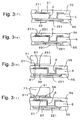
- a glass epoxy substrate which is used as the insulative substrate 5 is first prepared. Then, the upper and lower surfaces of the insulative substrate 5 are respectively coated by an upper surface metal foil 210 and a lower surface metal foil 220.
- the thickness t of the upper surface metal foil 210 is less than the thickness T of the lower surface metal foil 220. It is preferred that the coating of the upper surface metal foil 210 and the lower surface metal foil 220 be substances having thicknesses t and T, respectively.
- a surface treatment such as sandblasting, may be performed to adjust the thickness of the upper surface metal foil so that the thickness t of the upper surface metal foil 210 becomes less than the thickness T of the lower surface metal foil 220.
- upper surface and lower surface metal foils having the same thickness may be respectively applied to the upper surface and lower surface of the insulative substrate 5, and the upper surface metal foil may be etched until it is reduced to the thickness t to form the upper surface metal foil 210.
- the upper surface metal foil 210 and the lower surface metal foil 220 are preferably copper foils.
- a portion of the upper surface metal foil 210 corresponding to a blind via hole formation portion 35 of the insulative substrate 5 is etched to form an opening 213.
- a laser 8 is emitted against the surface of the surface of the insulative substrate 5 exposed by the opening 213, or the blind via hole formation portion 35. This forms the blind via hole 3, the bottom of which is the lower surface metal foil 220, as shown in Fig. 3(c).
- a chemical copper plating and an electric copper plating are applied to the wall of the blind via hole 3 to form the metal plating film 23.
- the surfaces of the upper surface metal foil 210 and the lower surface metal foil 220 are also coated by the metal plating film 23.
- the upper surface metal foil 210 and the lower surface metal foil 220 are etched to form the upper surface pattern 21 and the lower surface pattern 22.
- solder resist 55 is applied to the upper surface and lower surface of the insulative substrate 5.
- the solder resist 55 is applied so that a connection ball adhering portion 211 of the upper surface pattern 21 and a solder ball adhering portion 221 of the lower surface pattern 22 are exposed.
- a metal plating film 231 which is formed from nickel and gold, is applied to the connection ball adhering portion 211 of the upper surface pattern 21 and the solder ball adhering portion 221 of the lower surface pattern 22.
- connection ball adhering portion 211 of the upper surface pattern 21 by the connection ball 61, which is formed from solder.
- a filling material 59 such as an epoxy resin.
- the printed circuit board 4 of Figs. 1 and 2 is manufactured as described above.
- the thickness t of the upper surface metal foil 210 is less than the thickness T of the lower surface metal foil 220.
- this facilitates etching when etching the thin upper surface metal foil 210 to form the upper surface pattern 21.
- the thick lower surface metal foil 220 is not damaged by the emission of the laser 8 during formation of the blind via hole.
- the manufacturing method of the present embodiment enables the upper surface pattern 21 to be easily formed through etching. Further, the lower surface pattern 22, which is the bottom of the blind via hole, is prevented from being damaged by the laser emission during formation of the blind via hole, and a conductor is applied to the blind via hole 3 in a satisfactory state.
Landscapes
- Engineering & Computer Science (AREA)
- Microelectronics & Electronic Packaging (AREA)
- Manufacturing & Machinery (AREA)
- Physics & Mathematics (AREA)
- General Physics & Mathematics (AREA)
- Condensed Matter Physics & Semiconductors (AREA)
- Ceramic Engineering (AREA)
- Computer Hardware Design (AREA)
- Power Engineering (AREA)
- Optics & Photonics (AREA)
- Printing Elements For Providing Electric Connections Between Printed Circuits (AREA)
- Production Of Multi-Layered Print Wiring Board (AREA)
- Structure Of Printed Boards (AREA)
- Manufacturing Of Printed Circuit Boards (AREA)
- Manufacturing Of Printed Wiring (AREA)
Abstract

Description
Claims (8)
- A method for manufacturing a printed circuit board characterized by the steps of:coating a lower surface and an upper surface of an insulative substrate respectively with a lower surface metal foil and a lower surface metal foil, the thickness of which is less than that of the lower surface metal foil;forming an opening in the upper surface metal foil at a location corresponding to a blind via hole formation portion of the insulative substrate;forming a blind via hole, the bottom of which is the lower surface metal foil, by emitting a laser against the blind via hole formation portion through the opening;applying a conductor to the blind via hole; andforming an upper surface pattern and a lower surface pattern by respectively etching the upper surface metal foil and the lower surface metal foil.
- A method for manufacturing a printed circuit board characterized by the steps of:coating a lower surface and an upper surface of an insulative substrate respectively with a lower surface metal foil and an upper surface metal foil, the thickness of which is less than that of the lower surface metal foil;forming an upper surface pattern and a lower surface pattern by respectively etching the upper surface metal foil and the lower surface metal foil, wherein the upper surface pattern has an opening exposing the upper surface of the insulative substrate at a location corresponding to a blind via hole formation portion, and the lower surface pattern covers the lower surface of the insulative substrate at a location corresponding to the blind via hole formation portion;forming a blind via hole, the bottom of which is the lower surface pattern, by emitting a laser against the insulative substrate through the opening; andapplying a conductor to the blind via hole.
- The printed circuit board manufacturing method according to claim 1 or 2, characterized in that the upper surface and lower surface metal foil coating step includes a step of coating the upper surface and the lower surface, respectively, with an upper surface metal foil and a lower surface metal foil that have the same thickness, and a step for etching the upper surface metal foil.
- The printed circuit board manufacturing method according to claim 1 or 2, characterized in that the upper surface and lower surface metal foil coating step includes a step for coating the upper surface and the lower surface, respectively, with an upper surface metal foil and a lower surface metal foil that have the same thickness, and a step for further coating the lower surface metal foil with a metal plating film.
- The printed circuit board manufacturing method according to claim 1 or 2, characterized in that the upper surface and lower surface metal foil coating step includes a step for coating the upper surface and the lower surface, respectively, with an upper surface metal foil and a lower surface metal foil that have the same thickness, and a step for performing a sandblast treatment to the upper surface metal foil so that the thickness of the upper surface metal foil becomes less that of the lower surface metal foil.
- The printed circuit board manufacturing method according to claim 1 or 2, characterized in that the thickness of the upper surface pattern is 2 to 12µm.
- The printed circuit board manufacturing method according to claim 1 or 2, characterized in that the thickness of the lower surface pattern is 15 to 25µm.
- A printed circuit board characterized by:an insulative substrate;an upper surface pattern and a lower surface pattern provided, respectively, on an upper surface and a lower surface of the insulative substrate; anda blind via hole for electrically connecting the upper surface pattern and the lower surface pattern, wherein an upper portion of the blind via hole is opened and a bottom of the blind via hole is covered by the lower surface pattern, the thickness of the upper surface pattern being less than that of the lower surface pattern.
Priority Applications (1)
| Application Number | Priority Date | Filing Date | Title |
|---|---|---|---|
| EP06003039A EP1659841B1 (en) | 1998-07-08 | 1999-07-07 | Printed circuit board |
Applications Claiming Priority (3)
| Application Number | Priority Date | Filing Date | Title |
|---|---|---|---|
| JP19299298 | 1998-07-08 | ||
| JP10192992A JP2000031640A (en) | 1998-07-08 | 1998-07-08 | Printed wiring board and manufacture thereof |
| PCT/JP1999/003664 WO2000003572A1 (en) | 1998-07-08 | 1999-07-07 | Printed wiring board and method for producing the same |
Related Child Applications (1)
| Application Number | Title | Priority Date | Filing Date |
|---|---|---|---|
| EP06003039A Division EP1659841B1 (en) | 1998-07-08 | 1999-07-07 | Printed circuit board |
Publications (3)
| Publication Number | Publication Date |
|---|---|
| EP1102525A1 true EP1102525A1 (en) | 2001-05-23 |
| EP1102525A4 EP1102525A4 (en) | 2005-10-26 |
| EP1102525B1 EP1102525B1 (en) | 2007-09-19 |
Family
ID=16300433
Family Applications (2)
| Application Number | Title | Priority Date | Filing Date |
|---|---|---|---|
| EP99929729A Expired - Lifetime EP1102525B1 (en) | 1998-07-08 | 1999-07-07 | Printed wiring board and method for producing the same |
| EP06003039A Expired - Lifetime EP1659841B1 (en) | 1998-07-08 | 1999-07-07 | Printed circuit board |
Family Applications After (1)
| Application Number | Title | Priority Date | Filing Date |
|---|---|---|---|
| EP06003039A Expired - Lifetime EP1659841B1 (en) | 1998-07-08 | 1999-07-07 | Printed circuit board |
Country Status (6)
| Country | Link |
|---|---|
| US (1) | US6715204B1 (en) |
| EP (2) | EP1102525B1 (en) |
| JP (1) | JP2000031640A (en) |
| KR (2) | KR100514641B1 (en) |
| DE (2) | DE69937153T2 (en) |
| WO (1) | WO2000003572A1 (en) |
Cited By (4)
| Publication number | Priority date | Publication date | Assignee | Title |
|---|---|---|---|---|
| WO2003092344A1 (en) * | 2002-04-24 | 2003-11-06 | Ube Industries, Ltd. | Production of via hole in flexible circuit printable board |
| US7243425B2 (en) * | 2004-12-24 | 2007-07-17 | Cmk Corporation | Printed wiring board and method of manufacturing the same |
| CN103264227A (en) * | 2013-04-11 | 2013-08-28 | 温州大学 | Method of removing metal film covering surface of polymer substrate by direct laser etching |
| WO2014029626A2 (en) * | 2012-08-23 | 2014-02-27 | Continental Automotive Gmbh | Printed circuit board |
Families Citing this family (58)
| Publication number | Priority date | Publication date | Assignee | Title |
|---|---|---|---|---|
| US6598291B2 (en) * | 1998-03-20 | 2003-07-29 | Viasystems, Inc. | Via connector and method of making same |
| US6930256B1 (en) | 2002-05-01 | 2005-08-16 | Amkor Technology, Inc. | Integrated circuit substrate having laser-embedded conductive patterns and method therefor |
| JP2003069232A (en) * | 2001-08-30 | 2003-03-07 | Hitachi Chem Co Ltd | Wiring board and its manufacturing method |
| US7633765B1 (en) | 2004-03-23 | 2009-12-15 | Amkor Technology, Inc. | Semiconductor package including a top-surface metal layer for implementing circuit features |
| US7670962B2 (en) | 2002-05-01 | 2010-03-02 | Amkor Technology, Inc. | Substrate having stiffener fabrication method |
| US9691635B1 (en) | 2002-05-01 | 2017-06-27 | Amkor Technology, Inc. | Buildup dielectric layer having metallization pattern semiconductor package fabrication method |
| US7399661B2 (en) * | 2002-05-01 | 2008-07-15 | Amkor Technology, Inc. | Method for making an integrated circuit substrate having embedded back-side access conductors and vias |
| US7548430B1 (en) | 2002-05-01 | 2009-06-16 | Amkor Technology, Inc. | Buildup dielectric and metallization process and semiconductor package |
| US7028400B1 (en) * | 2002-05-01 | 2006-04-18 | Amkor Technology, Inc. | Integrated circuit substrate having laser-exposed terminals |
| US20080043447A1 (en) * | 2002-05-01 | 2008-02-21 | Amkor Technology, Inc. | Semiconductor package having laser-embedded terminals |
| US11081370B2 (en) | 2004-03-23 | 2021-08-03 | Amkor Technology Singapore Holding Pte. Ltd. | Methods of manufacturing an encapsulated semiconductor device |
| US10811277B2 (en) | 2004-03-23 | 2020-10-20 | Amkor Technology, Inc. | Encapsulated semiconductor package |
| US8826531B1 (en) | 2005-04-05 | 2014-09-09 | Amkor Technology, Inc. | Method for making an integrated circuit substrate having laminated laser-embedded circuit layers |
| JP5042501B2 (en) * | 2006-01-19 | 2012-10-03 | 株式会社フジクラ | Manufacturing method of semiconductor device |
| US7589398B1 (en) | 2006-10-04 | 2009-09-15 | Amkor Technology, Inc. | Embedded metal features structure |
| US7550857B1 (en) | 2006-11-16 | 2009-06-23 | Amkor Technology, Inc. | Stacked redistribution layer (RDL) die assembly package |
| KR100843211B1 (en) | 2006-11-23 | 2008-07-02 | 삼성전자주식회사 | Wafer backside Metal layer routing method, structure of the same, chip package stacking method, and chip package stacking structure thereof |
| US7750250B1 (en) | 2006-12-22 | 2010-07-06 | Amkor Technology, Inc. | Blind via capture pad structure |
| JP2008155274A (en) * | 2006-12-26 | 2008-07-10 | Disco Abrasive Syst Ltd | Method of machining wafer |
| US7752752B1 (en) | 2007-01-09 | 2010-07-13 | Amkor Technology, Inc. | Method of fabricating an embedded circuit pattern |
| US8323771B1 (en) | 2007-08-15 | 2012-12-04 | Amkor Technology, Inc. | Straight conductor blind via capture pad structure and fabrication method |
| KR100999515B1 (en) * | 2008-11-14 | 2010-12-09 | 삼성전기주식회사 | Manufacturing method of printed circuit board |
| US8872329B1 (en) | 2009-01-09 | 2014-10-28 | Amkor Technology, Inc. | Extended landing pad substrate package structure and method |
| US7960827B1 (en) | 2009-04-09 | 2011-06-14 | Amkor Technology, Inc. | Thermal via heat spreader package and method |
| US8623753B1 (en) | 2009-05-28 | 2014-01-07 | Amkor Technology, Inc. | Stackable protruding via package and method |
| KR101067223B1 (en) * | 2009-06-10 | 2011-09-22 | 삼성전기주식회사 | Package substrate |
| US8222538B1 (en) | 2009-06-12 | 2012-07-17 | Amkor Technology, Inc. | Stackable via package and method |
| US8471154B1 (en) | 2009-08-06 | 2013-06-25 | Amkor Technology, Inc. | Stackable variable height via package and method |
| US8796561B1 (en) | 2009-10-05 | 2014-08-05 | Amkor Technology, Inc. | Fan out build up substrate stackable package and method |
| US8937381B1 (en) | 2009-12-03 | 2015-01-20 | Amkor Technology, Inc. | Thin stackable package and method |
| US9691734B1 (en) | 2009-12-07 | 2017-06-27 | Amkor Technology, Inc. | Method of forming a plurality of electronic component packages |
| US8536462B1 (en) | 2010-01-22 | 2013-09-17 | Amkor Technology, Inc. | Flex circuit package and method |
| US8300423B1 (en) | 2010-05-25 | 2012-10-30 | Amkor Technology, Inc. | Stackable treated via package and method |
| US8294276B1 (en) | 2010-05-27 | 2012-10-23 | Amkor Technology, Inc. | Semiconductor device and fabricating method thereof |
| JP2012028374A (en) * | 2010-07-20 | 2012-02-09 | Furukawa Electric Co Ltd:The | Interposer, manufacturing method thereof, semiconductor package, and manufacturing method thereof |
| US8338229B1 (en) | 2010-07-30 | 2012-12-25 | Amkor Technology, Inc. | Stackable plasma cleaned via package and method |
| US8717775B1 (en) | 2010-08-02 | 2014-05-06 | Amkor Technology, Inc. | Fingerprint sensor package and method |
| KR101278426B1 (en) * | 2010-09-02 | 2013-06-24 | 삼성전기주식회사 | Manufacturing method of Semiconductor package substrate |
| US8337657B1 (en) | 2010-10-27 | 2012-12-25 | Amkor Technology, Inc. | Mechanical tape separation package and method |
| US8482134B1 (en) | 2010-11-01 | 2013-07-09 | Amkor Technology, Inc. | Stackable package and method |
| US9748154B1 (en) | 2010-11-04 | 2017-08-29 | Amkor Technology, Inc. | Wafer level fan out semiconductor device and manufacturing method thereof |
| US8525318B1 (en) | 2010-11-10 | 2013-09-03 | Amkor Technology, Inc. | Semiconductor device and fabricating method thereof |
| US8557629B1 (en) | 2010-12-03 | 2013-10-15 | Amkor Technology, Inc. | Semiconductor device having overlapped via apertures |
| US8535961B1 (en) | 2010-12-09 | 2013-09-17 | Amkor Technology, Inc. | Light emitting diode (LED) package and method |
| US9721872B1 (en) | 2011-02-18 | 2017-08-01 | Amkor Technology, Inc. | Methods and structures for increasing the allowable die size in TMV packages |
| US9013011B1 (en) | 2011-03-11 | 2015-04-21 | Amkor Technology, Inc. | Stacked and staggered die MEMS package and method |
| KR101140113B1 (en) | 2011-04-26 | 2012-04-30 | 앰코 테크놀로지 코리아 주식회사 | Semiconductor device |
| US8653674B1 (en) | 2011-09-15 | 2014-02-18 | Amkor Technology, Inc. | Electronic component package fabrication method and structure |
| US8633598B1 (en) | 2011-09-20 | 2014-01-21 | Amkor Technology, Inc. | Underfill contacting stacking balls package fabrication method and structure |
| US9029962B1 (en) | 2011-10-12 | 2015-05-12 | Amkor Technology, Inc. | Molded cavity substrate MEMS package fabrication method and structure |
| JP2013123035A (en) * | 2011-11-09 | 2013-06-20 | Ngk Spark Plug Co Ltd | Manufacturing method for multilayer wiring board |
| JP2013187255A (en) * | 2012-03-06 | 2013-09-19 | Ngk Spark Plug Co Ltd | Wiring board manufacturing method |
| US9799592B2 (en) | 2013-11-19 | 2017-10-24 | Amkor Technology, Inc. | Semicondutor device with through-silicon via-less deep wells |
| KR101366461B1 (en) | 2012-11-20 | 2014-02-26 | 앰코 테크놀로지 코리아 주식회사 | Semiconductor device and manufacturing method thereof |
| KR101488590B1 (en) | 2013-03-29 | 2015-01-30 | 앰코 테크놀로지 코리아 주식회사 | Semiconductor device and manufacturing method thereof |
| KR101607981B1 (en) | 2013-11-04 | 2016-03-31 | 앰코 테크놀로지 코리아 주식회사 | Interposer and method for manufacturing the same, and semiconductor package using the same |
| CN105764236B (en) * | 2015-04-29 | 2019-03-05 | 生益电子股份有限公司 | A kind of processing method and PCB of PCB |
| US9960328B2 (en) | 2016-09-06 | 2018-05-01 | Amkor Technology, Inc. | Semiconductor device and manufacturing method thereof |
Citations (5)
| Publication number | Priority date | Publication date | Assignee | Title |
|---|---|---|---|---|
| US4644130A (en) * | 1984-05-18 | 1987-02-17 | Siemens Aktiengesellschaft | Method for creating blind holes in a laminated structure |
| US4917758A (en) * | 1988-05-20 | 1990-04-17 | Mitsubishi Gas Chemical Company, Inc. | Method for preparing thin copper foil-clad substrate for circuit boards |
| WO1991018489A1 (en) * | 1990-05-16 | 1991-11-28 | Olin Corporation | Gtab manufacturing process and the product produced thereby |
| JPH0537124A (en) * | 1991-07-26 | 1993-02-12 | Mitsubishi Electric Corp | Manufacture of printed wiring board |
| US5639389A (en) * | 1994-02-21 | 1997-06-17 | Dyconex Patente Ag | Process for the production of structures |
Family Cites Families (14)
| Publication number | Priority date | Publication date | Assignee | Title |
|---|---|---|---|---|
| JPS61176193A (en) | 1985-01-31 | 1986-08-07 | 日立化成工業株式会社 | Manufacture of wiring board |
| JPH01318281A (en) * | 1988-06-20 | 1989-12-22 | Shin Etsu Chem Co Ltd | Manufacture of elexible printed wiring board |
| FR2637151A1 (en) * | 1988-09-29 | 1990-03-30 | Commissariat Energie Atomique | METHOD OF MAKING ELECTRICAL CONNECTIONS THROUGH A SUBSTRATE |
| JP2670700B2 (en) * | 1989-03-20 | 1997-10-29 | 日立精工株式会社 | Printed circuit board and printed circuit board manufacturing method |
| JP3129795B2 (en) | 1991-11-15 | 2001-01-31 | 株式会社東芝 | Stone crushing equipment |
| JPH05200574A (en) * | 1992-01-28 | 1993-08-10 | Furukawa Electric Co Ltd:The | Manufacture of insulating substrate with both surface conductor layers having through hole |
| JPH08139223A (en) * | 1994-11-09 | 1996-05-31 | Mitsubishi Electric Corp | Semiconductor device |
| JPH08148824A (en) * | 1994-11-16 | 1996-06-07 | Hitachi Chem Co Ltd | Manufacture of wiring board |
| JPH08298298A (en) * | 1995-04-26 | 1996-11-12 | Mitsubishi Gas Chem Co Inc | Semiconductor carrier |
| JPH0946042A (en) * | 1995-08-02 | 1997-02-14 | Fuji Kiko Denshi Kk | Circuit forming method in printed wiring board |
| JPH09148698A (en) * | 1995-11-28 | 1997-06-06 | Sharp Corp | Double-sided printed wiring board and its manufacture |
| US5764485A (en) * | 1996-04-19 | 1998-06-09 | Lebaschi; Ali | Multi-layer PCB blockade-via pad-connection |
| AU5238898A (en) * | 1996-11-08 | 1998-05-29 | W.L. Gore & Associates, Inc. | Method for reducing via inductance in an electronic assembly and device |
| JPH11266068A (en) * | 1998-01-14 | 1999-09-28 | Canon Inc | Wiring substrate and its manufacture |
-
1998
- 1998-07-08 JP JP10192992A patent/JP2000031640A/en active Pending
-
1999
- 1999-07-07 US US09/720,953 patent/US6715204B1/en not_active Expired - Lifetime
- 1999-07-07 KR KR10-2000-7014889A patent/KR100514641B1/en not_active IP Right Cessation
- 1999-07-07 DE DE69937153T patent/DE69937153T2/en not_active Expired - Lifetime
- 1999-07-07 KR KR1020057012866A patent/KR100719287B1/en not_active IP Right Cessation
- 1999-07-07 DE DE69943290T patent/DE69943290D1/en not_active Expired - Lifetime
- 1999-07-07 EP EP99929729A patent/EP1102525B1/en not_active Expired - Lifetime
- 1999-07-07 WO PCT/JP1999/003664 patent/WO2000003572A1/en active IP Right Grant
- 1999-07-07 EP EP06003039A patent/EP1659841B1/en not_active Expired - Lifetime
Patent Citations (5)
| Publication number | Priority date | Publication date | Assignee | Title |
|---|---|---|---|---|
| US4644130A (en) * | 1984-05-18 | 1987-02-17 | Siemens Aktiengesellschaft | Method for creating blind holes in a laminated structure |
| US4917758A (en) * | 1988-05-20 | 1990-04-17 | Mitsubishi Gas Chemical Company, Inc. | Method for preparing thin copper foil-clad substrate for circuit boards |
| WO1991018489A1 (en) * | 1990-05-16 | 1991-11-28 | Olin Corporation | Gtab manufacturing process and the product produced thereby |
| JPH0537124A (en) * | 1991-07-26 | 1993-02-12 | Mitsubishi Electric Corp | Manufacture of printed wiring board |
| US5639389A (en) * | 1994-02-21 | 1997-06-17 | Dyconex Patente Ag | Process for the production of structures |
Non-Patent Citations (2)
| Title |
|---|
| PATENT ABSTRACTS OF JAPAN vol. 017, no. 328 (E-1385), 22 June 1993 (1993-06-22) & JP 05 037124 A (MITSUBISHI ELECTRIC CORP), 12 February 1993 (1993-02-12) * |
| See also references of WO0003572A1 * |
Cited By (8)
| Publication number | Priority date | Publication date | Assignee | Title |
|---|---|---|---|---|
| WO2003092344A1 (en) * | 2002-04-24 | 2003-11-06 | Ube Industries, Ltd. | Production of via hole in flexible circuit printable board |
| US7918021B2 (en) | 2002-04-24 | 2011-04-05 | Ube Industries, Ltd. | Production of via hole in a flexible printed circuit board by applying a laser or punch |
| CN1663329B (en) * | 2002-04-24 | 2011-05-18 | 宇部兴产株式会社 | Production of via hole in flexible circuit printable board |
| US7243425B2 (en) * | 2004-12-24 | 2007-07-17 | Cmk Corporation | Printed wiring board and method of manufacturing the same |
| WO2014029626A2 (en) * | 2012-08-23 | 2014-02-27 | Continental Automotive Gmbh | Printed circuit board |
| WO2014029626A3 (en) * | 2012-08-23 | 2014-09-12 | Continental Automotive Gmbh | Printed circuit board |
| CN103264227A (en) * | 2013-04-11 | 2013-08-28 | 温州大学 | Method of removing metal film covering surface of polymer substrate by direct laser etching |
| CN103264227B (en) * | 2013-04-11 | 2015-05-13 | 温州大学 | Method of removing metal film covering surface of polymer substrate by direct laser etching |
Also Published As
| Publication number | Publication date |
|---|---|
| EP1659841B1 (en) | 2011-03-16 |
| KR20010071631A (en) | 2001-07-28 |
| EP1102525B1 (en) | 2007-09-19 |
| KR100719287B1 (en) | 2007-05-18 |
| KR20050085961A (en) | 2005-08-29 |
| KR100514641B1 (en) | 2005-09-14 |
| EP1659841A2 (en) | 2006-05-24 |
| DE69937153D1 (en) | 2007-10-31 |
| EP1102525A4 (en) | 2005-10-26 |
| DE69943290D1 (en) | 2011-04-28 |
| US6715204B1 (en) | 2004-04-06 |
| DE69937153T2 (en) | 2008-06-19 |
| WO2000003572A1 (en) | 2000-01-20 |
| JP2000031640A (en) | 2000-01-28 |
| EP1659841A3 (en) | 2009-02-25 |
Similar Documents
| Publication | Publication Date | Title |
|---|---|---|
| US6715204B1 (en) | Printed wiring board and method for producing the same | |
| US6618940B2 (en) | Fine pitch circuitization with filled plated through holes | |
| US7084509B2 (en) | Electronic package with filled blinds vias | |
| US20060180346A1 (en) | High aspect ratio plated through holes in a printed circuit board | |
| US4867839A (en) | Process for forming a circuit substrate | |
| KR100751984B1 (en) | Process for producing electronic component and electronic component | |
| US7197820B2 (en) | Circuit board and its manufacturing method | |
| KR20010105366A (en) | Method of manufacturing multilayer wiring board | |
| EP1146780A2 (en) | Circuit board and method of manufacture | |
| US9744624B2 (en) | Method for manufacturing circuit board | |
| KR100671541B1 (en) | A manufacturing method of printed circuit embedded board | |
| US8197702B2 (en) | Manufacturing method of printed circuit board | |
| EP1049364A1 (en) | Method of manufacturing multilayer wiring boards | |
| US20020185311A1 (en) | Printed wiring board having a discontinuous plating layer and method of manufacture thereof | |
| EP0949855A3 (en) | Multilayer circuit board | |
| US6998291B2 (en) | Cost-reducing and process-simplifying wiring board and manufacturing method thereof | |
| JP3278302B2 (en) | Method for manufacturing double-sided wiring type film carrier | |
| JPH11220256A (en) | Manufacturing method of ceramic wiring board | |
| JP3759755B2 (en) | How to make raised metal contacts on electrical circuits for permanent connection | |
| JP2000151107A (en) | Multilayer printed wiring board and manufacture thereof | |
| KR100473337B1 (en) | electrical conductive via forming method of substrate for semiconductor package | |
| KR100468195B1 (en) | A manufacturing process of multi-layer printed circuit board | |
| EP1014436A2 (en) | Process for producing a substrate | |
| JPH08186357A (en) | Printed wiring board and manufacture thereof | |
| JP2000188471A (en) | Printed wiring board and its manufacture |
Legal Events
| Date | Code | Title | Description |
|---|---|---|---|
| PUAI | Public reference made under article 153(3) epc to a published international application that has entered the european phase |
Free format text: ORIGINAL CODE: 0009012 |
|
| 17P | Request for examination filed |
Effective date: 20010104 |
|
| AK | Designated contracting states |
Kind code of ref document: A1 Designated state(s): AT BE CH CY DE DK ES FI FR GB GR IE IT LI LU MC NL PT SE |
|
| A4 | Supplementary search report drawn up and despatched |
Effective date: 20050908 |
|
| GRAP | Despatch of communication of intention to grant a patent |
Free format text: ORIGINAL CODE: EPIDOSNIGR1 |
|
| RBV | Designated contracting states (corrected) |
Designated state(s): DE GB |
|
| GRAS | Grant fee paid |
Free format text: ORIGINAL CODE: EPIDOSNIGR3 |
|
| GRAA | (expected) grant |
Free format text: ORIGINAL CODE: 0009210 |
|
| AK | Designated contracting states |
Kind code of ref document: B1 Designated state(s): DE GB |
|
| REG | Reference to a national code |
Ref country code: GB Ref legal event code: FG4D |
|
| REF | Corresponds to: |
Ref document number: 69937153 Country of ref document: DE Date of ref document: 20071031 Kind code of ref document: P |
|
| PLBE | No opposition filed within time limit |
Free format text: ORIGINAL CODE: 0009261 |
|
| STAA | Information on the status of an ep patent application or granted ep patent |
Free format text: STATUS: NO OPPOSITION FILED WITHIN TIME LIMIT |
|
| 26N | No opposition filed |
Effective date: 20080620 |
|
| GBPC | Gb: european patent ceased through non-payment of renewal fee |
Effective date: 20080707 |
|
| PG25 | Lapsed in a contracting state [announced via postgrant information from national office to epo] |
Ref country code: GB Free format text: LAPSE BECAUSE OF NON-PAYMENT OF DUE FEES Effective date: 20080707 |
|
| PGFP | Annual fee paid to national office [announced via postgrant information from national office to epo] |
Ref country code: DE Payment date: 20120704 Year of fee payment: 14 |
|
| PG25 | Lapsed in a contracting state [announced via postgrant information from national office to epo] |
Ref country code: DE Free format text: LAPSE BECAUSE OF NON-PAYMENT OF DUE FEES Effective date: 20140201 |
|
| REG | Reference to a national code |
Ref country code: DE Ref legal event code: R119 Ref document number: 69937153 Country of ref document: DE Effective date: 20140201 |