EP1102233A2 - Dispositif électronique avec un écran de visualisation - Google Patents
Dispositif électronique avec un écran de visualisation Download PDFInfo
- Publication number
- EP1102233A2 EP1102233A2 EP00123452A EP00123452A EP1102233A2 EP 1102233 A2 EP1102233 A2 EP 1102233A2 EP 00123452 A EP00123452 A EP 00123452A EP 00123452 A EP00123452 A EP 00123452A EP 1102233 A2 EP1102233 A2 EP 1102233A2
- Authority
- EP
- European Patent Office
- Prior art keywords
- contrast
- electronic device
- display
- display areas
- display unit
- Prior art date
- Legal status (The legal status is an assumption and is not a legal conclusion. Google has not performed a legal analysis and makes no representation as to the accuracy of the status listed.)
- Granted
Links
- 238000000034 method Methods 0.000 claims abstract description 17
- 238000012545 processing Methods 0.000 claims abstract description 3
- 230000008859 change Effects 0.000 claims description 14
- 230000003287 optical effect Effects 0.000 claims description 9
- 230000009467 reduction Effects 0.000 claims description 9
- 230000008569 process Effects 0.000 claims description 4
- 238000013459 approach Methods 0.000 description 1
- 238000013461 design Methods 0.000 description 1
- 238000001514 detection method Methods 0.000 description 1
- 238000010586 diagram Methods 0.000 description 1
- 238000006073 displacement reaction Methods 0.000 description 1
- 210000001747 pupil Anatomy 0.000 description 1
- 230000002123 temporal effect Effects 0.000 description 1
- 238000012549 training Methods 0.000 description 1
- 230000007704 transition Effects 0.000 description 1
- 230000000007 visual effect Effects 0.000 description 1
Images


Classifications
-
- G—PHYSICS
- G09—EDUCATION; CRYPTOGRAPHY; DISPLAY; ADVERTISING; SEALS
- G09G—ARRANGEMENTS OR CIRCUITS FOR CONTROL OF INDICATING DEVICES USING STATIC MEANS TO PRESENT VARIABLE INFORMATION
- G09G5/00—Control arrangements or circuits for visual indicators common to cathode-ray tube indicators and other visual indicators
-
- B60K2360/33—
-
- G—PHYSICS
- G09—EDUCATION; CRYPTOGRAPHY; DISPLAY; ADVERTISING; SEALS
- G09G—ARRANGEMENTS OR CIRCUITS FOR CONTROL OF INDICATING DEVICES USING STATIC MEANS TO PRESENT VARIABLE INFORMATION
- G09G2320/00—Control of display operating conditions
- G09G2320/06—Adjustment of display parameters
- G09G2320/066—Adjustment of display parameters for control of contrast
-
- G—PHYSICS
- G09—EDUCATION; CRYPTOGRAPHY; DISPLAY; ADVERTISING; SEALS
- G09G—ARRANGEMENTS OR CIRCUITS FOR CONTROL OF INDICATING DEVICES USING STATIC MEANS TO PRESENT VARIABLE INFORMATION
- G09G2340/00—Aspects of display data processing
- G09G2340/14—Solving problems related to the presentation of information to be displayed
-
- G—PHYSICS
- G09—EDUCATION; CRYPTOGRAPHY; DISPLAY; ADVERTISING; SEALS
- G09G—ARRANGEMENTS OR CIRCUITS FOR CONTROL OF INDICATING DEVICES USING STATIC MEANS TO PRESENT VARIABLE INFORMATION
- G09G2360/00—Aspects of the architecture of display systems
- G09G2360/14—Detecting light within display terminals, e.g. using a single or a plurality of photosensors
- G09G2360/144—Detecting light within display terminals, e.g. using a single or a plurality of photosensors the light being ambient light
Definitions
- the invention relates to an electronic device with an optical display unit, which has a plurality of display areas, an operating unit, means for processing input commands entered via the control unit are, as well as means for controlling the display unit. Furthermore, the Invention a method for controlling the contrast of individual areas of a Display unit with several display areas for displaying information.
- the aforementioned electronic device is, for example, in the form of a Known navigation system for use in motor vehicles.
- the brightness of the optical display unit changed to be optimal both during the day and when driving at night To achieve information display.
- the Brightness of the display to a lower level when the headlights are switched on to reduce.
- a display unit is known from US Pat. No. 5,617,112, which has a light sensor for detection of the intensity of the ambient light. Depending on the Different light levels of the light sensor are signal Display unit set. The transition between the brightness levels takes place in such a way that the rate of change to the rate of change is adapted to the degree of opening of the human pupil.
- the brightness is thus adjusted the display essentially to distinguish between a day and Night operation and thus to adapt to the intensity of the ambient light.
- the object of the invention is therefore a generic electronic Training facility such that the different meaning of Information in various display areas of the display unit in particular is taken into account at night.
- Another job is a method of controlling the contrast of individual areas to indicate a display unit.
- the first object is achieved in that in the electronic Establishment continues to provide means to determine the length of time since the last Actuation of the control unit and to compare this time period with a Default value and means for automatically changing the contrast individual display areas of the display unit are available and the automatic Change the contrast of individual display areas of the display unit depending on the result of the comparison of the length of time since the last The control unit is operated with the default value.
- the device according to the invention is therefore not like the previously known just a change in the brightness of the entire display unit for adjustment intended for day or night operation. Rather, it is provided that the contrast of individual areas that, for example, while driving from are of minor interest, is automatically changed.
- the length of time since the last actuation of the control unit is used. This time period is compared with a default value. exceeds the length of time since the control unit was last operated, the default value, so the contrast of individual display areas of the display unit is changed. In Usually the contrast of less important display areas reduced.
- the electronic device is one On-board computer of a motor vehicle, after a certain time Period of time the contrast of the area in which the day of the week or the date is reduced because this information is not provided by the driver continuously needed.
- a map with the current vehicle position, direction of travel as well as other areas are available when selecting them via the control unit can output additional information or the Destination can be entered.
- These latter functions too are not constantly needed while driving, while the Map display and / or the display of the direction of travel from constant interest for the driver.
- the contrast of the latter after the expiration of a certain one Duration automatically reduced after an entry via the control unit become.
- the control unit again automatically increases the contrast the display areas occur, the contrast of which was previously reduced. This makes it possible to see clearly again at any time all display areas. For example, if the driver wants one Navigation system to enter a new destination, by pressing a button on the control unit, for example, the corresponding previously darkened display areas back to normal brightness on a darker background so that the readability of the relevant information on the display unit is guaranteed.
- the change in the contrast of individual display areas can be different Depending on the type of representation of the display unit.
- the Representation of characters or symbols on display units for example can be designed as LCD displays, is generally between Distinguished between negative and positive presentation. With the positive display the characters and symbols shown are darker than the background of the Display unit. The reverse is true for the negative display.
- a reduction in Contrast can be achieved in that the brightness of the characters or Symbols are increased and the background brightness is adjusted accordingly.
- a Display unit with negative display is used to reduce the Contrast the brightness of the signs and symbols can be reduced and the approach the lower brightness of the background.
- a display unit can have both positive and negative areas.
- the contrast can therefore also be reduced in that the brightness of the background of individual display areas to the brightness of the Characters and symbols in this display area is adjusted.
- the contrast For display units with colored display of characters and symbols a different colored background it is also possible to change the contrast by changing the color of the background or the characters or symbols change.
- the characters or symbols are displayed in the Normal operation in red on a blue background Reduce the contrast of the representation of the characters or symbols in one Blue tone, which differs only slightly from the background. In this If the contrast is reduced, this is done solely by changing the color without changing the brightness. Furthermore, to reduce the contrast combinations of color and brightness changes are also possible.
- the change in contrast according to the invention can be individual Display areas also with a general change in the brightness of the Display depending on the ambient light or the time of day.
- the change in contrast according to the invention can be individual Display areas also with a general change in the brightness of the Display depending on the ambient light or the time of day.
- e.g. B. the automatic change of contrast of individual Display areas only when the vehicle headlights are switched on respectively. In this case, for example, there will be a flood when driving at night of the driver with too many visual stimuli.
- FIG. 1 are the components of a navigation system for motor vehicles shown schematically.
- the central component of the navigation system is the Computing unit (CPU) 1.
- An operating unit 2 is connected to the CPU 1 via for example the destination can be entered or selected.
- the Control unit 2 can be housed in the same housing as the CPU 1, however, the control unit 2 can also be designed as a remote control with the CPU 1, for example via an optical interface or a Radio interface is connected.
- With the CPU 2 is an optical output unit 3 connected, about the route guidance information and other Information is output.
- the route guidance information can continue to be output acoustically via a loudspeaker 4.
- the CPU 1 is also connected to a database 5, which contains the map data.
- the map data are stored, for example, on a CD-ROM.
- the navigation system contains a CD-ROM drive, which with the CPU 1 is connected. Based on the map data, the CPU 1 with known starting and destination in a known manner a calculation of optimal route can be carried out, which is then via the optical output unit 3 can be output.
- the navigation system also contains a receiver 6 for reception of satellite navigation signals.
- a satellite-independent position determination To be able to carry out, the navigation system also contains one Direction sensor 7 and a displacement sensor 8, which are also connected to the CPU 1 are connected so that with the help of a suitable program with these Signals a position determination is possible.
- Such a navigation system is known and does not form the content of the present invention. That in figure 1 illustrated navigation system is only explained here by way of example.
- the Invention is also with other configurations of navigation systems can be used, for example with so-called offboard navigation systems, where the route guidance information comes from outside be transmitted into the vehicle.
- the display unit of the navigation system is shown in more detail in FIG. Deviating from the illustration, the following description of a display unit with negative display, i.e. bright symbols on dark Background, outgoing.
- the output unit 3 contains a first area with a schematic diagram representation in this case, which shows the streets 9, 10, 11 and the vehicle position 12. In another area an arrow 13 indicates the direction of travel or an impending turn displayed. It is the map display and / or the arrow display information for the driver while driving to the destination are of constant interest.
- the display unit 3 has further display areas 14, 15, 16, 17, 18.
- the display area 18 shows, for example, the current one Day of the week, current date and time are displayed.
- the display areas 14, 15, 16, 17 can be selected via the control unit.
- the display area 14 is, for example, the entry of a destination allows.
- a complete route map is displayed shown on the display unit 3.
- area 16 is selected, a new route calculation carried out and when selecting area 17 further information is shown on the display unit 3.
- Selection of one of the display areas 14 to 17 can also be, for example another submenu can be called up.
- the display areas 14 to 18 are for the driver is usually of interest only before or at the start of a journey, for example, to enter the destination or a route calculation perform. In a navigation system according to the invention hence some or all of the output areas 14 to 18 after one predetermined time after the last entry via the control unit 2 in reduced their brightness.
- the determination of the length of time since the control unit was operated 2 as well as the comparison with a default value is software-based in the CPU 1 performed.
- the CPU 1 delivers the corresponding Output signals for the display unit 3, usually between the CPU 1 and the display unit 3 corresponding drivers or the like are interposed.
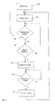
- FIG. 3 shows an example of a flow chart for the method according to the invention shown.
- Timer started.
- step 303 there is a regular query as to whether a Control element of control unit 2 was actuated. Became a control pressed, the timer starts again. However, was not a control element actuated, a query is made in step 304 as to whether the timer has expired is, that is, whether the length of time since the last actuation of an operating element is larger than the default value. Steps 303 and 304 will be repeats continuously until step 304 determines that the timer has expired is. In this case, in step 305, the brightness of individual predetermined ones Display areas reduced. This is followed in step 306 again a query as to whether an operating element was actuated. Is that the case, in step 307 the brightness of those display areas is increased again, where the brightness was previously reduced. The process then starts again with step 302.
- the time course of the brightness is shown in FIG. 4, with three brightness levels H1, H2, H3 are shown.
- the brightness level H1 is the Brightness of the background of the display.
- H3 is the normal one Brightness of the display denotes, while H2 the reduced brightness of the Indicates display areas whose brightness automatically depends on the length of time since the last actuation of an operating element can be changed.
- the brightness levels can also be used, for example, for day and day Night operation may be different.
- the last actuation of an operating element is said to have taken place at time t1, so that the timer is started at this time.
- Individual display areas on the brightness level H2 is reduced from time t2 during the period T from the brightness.
- This time period is ended by actuating an operating element of the operating unit again at time t4.
- the time span between the times t3 and t4 will, as a rule, be considerably longer in practical operation than the time intervals T off , T on or T delay than is shown in FIG.
- the brightness of the display areas is then increased again with previously reduced brightness. This is done one during the time period T and that the brightness level of the display areas H3, whose brightness was not reduced. This process is completed at time t5.
- the last actuation of an operating element then takes place at time t6, which thus corresponds to time t1 in terms of its function. At the time t6, therefore, the delay time T closes again galvanized followed it reduce the brightness from the time t7.
- the invention was made closer using a special navigation system explained.
Applications Claiming Priority (2)
| Application Number | Priority Date | Filing Date | Title |
|---|---|---|---|
| DE19956109 | 1999-11-22 | ||
| DE19956109A DE19956109A1 (de) | 1999-11-22 | 1999-11-22 | Elektronische Einrichtung mit einer Anzeigeeinheit |
Publications (3)
| Publication Number | Publication Date |
|---|---|
| EP1102233A2 true EP1102233A2 (fr) | 2001-05-23 |
| EP1102233A3 EP1102233A3 (fr) | 2001-05-30 |
| EP1102233B1 EP1102233B1 (fr) | 2009-06-24 |
Family
ID=7929898
Family Applications (1)
| Application Number | Title | Priority Date | Filing Date |
|---|---|---|---|
| EP00123452A Expired - Lifetime EP1102233B1 (fr) | 1999-11-22 | 2000-11-06 | Dispositif électronique avec un écran de visualisation |
Country Status (2)
| Country | Link |
|---|---|
| EP (1) | EP1102233B1 (fr) |
| DE (2) | DE19956109A1 (fr) |
Cited By (1)
| Publication number | Priority date | Publication date | Assignee | Title |
|---|---|---|---|---|
| EP1868169A1 (fr) * | 2006-06-09 | 2007-12-19 | Aruze Corporation | Machine de jeu |
Families Citing this family (2)
| Publication number | Priority date | Publication date | Assignee | Title |
|---|---|---|---|---|
| DE10144752A1 (de) * | 2001-09-11 | 2003-03-27 | Volkswagen Ag | Verfahren und Vorrichtung zur Übertragung von Information in ein Kraftfahrzeug |
| DE102004019329B4 (de) * | 2004-04-21 | 2016-11-03 | BSH Hausgeräte GmbH | Geschirrspülmaschine mit optischer Betriebsablaufanzeige |
Citations (3)
| Publication number | Priority date | Publication date | Assignee | Title |
|---|---|---|---|---|
| US5598565A (en) | 1993-12-29 | 1997-01-28 | Intel Corporation | Method and apparatus for screen power saving |
| US5617112A (en) | 1993-12-28 | 1997-04-01 | Nec Corporation | Display control device for controlling brightness of a display installed in a vehicular cabin |
| WO1999053472A1 (fr) | 1998-04-15 | 1999-10-21 | Cambridge Display Technology Ltd. | Dispositif de commande d'affichage comprenant des modes d'economie de la consommation d'energie |
Family Cites Families (11)
| Publication number | Priority date | Publication date | Assignee | Title |
|---|---|---|---|---|
| DE4012750A1 (de) * | 1990-04-21 | 1991-10-24 | Hoechst Ag | Ferroelektrisches fluessigkristalldisplay mit hohem kontrast und hoher helligkeit |
| JPH04250489A (ja) * | 1991-01-10 | 1992-09-07 | Pioneer Electron Corp | 車載ナビゲ−ション装置 |
| JPH0843811A (ja) * | 1994-08-02 | 1996-02-16 | Hitachi Ltd | 液晶表示装置 |
| DE19531824A1 (de) * | 1994-10-07 | 1996-04-11 | Mannesmann Ag | Verfahren zur Ansteuerung einer Anzeigevorrichtung zur Zielführung eines Fahrzeugs |
| US5818553A (en) * | 1995-04-10 | 1998-10-06 | Norand Corporation | Contrast control for a backlit LCD |
| WO1997003432A1 (fr) * | 1995-07-13 | 1997-01-30 | Motorola Inc. | Procede et dispositif de retroeclairage pour des temps differents de l'ecran d'un appareil alimente par batterie |
| JPH09123848A (ja) * | 1995-11-06 | 1997-05-13 | Toyota Motor Corp | 車両用情報表示装置 |
| US6271813B1 (en) * | 1996-08-30 | 2001-08-07 | Lear Automotive Dearborn, Inc. | Voltage control for adjusting the brightness of a screen display |
| JP2891955B2 (ja) * | 1997-02-14 | 1999-05-17 | 日本電気移動通信株式会社 | Lcd表示装置 |
| DE19755470A1 (de) * | 1997-02-24 | 1998-09-24 | Marius Dipl Ing Tegethoff | Anzeigesystem für Fahrzeuge |
| JP3700387B2 (ja) * | 1998-04-15 | 2005-09-28 | セイコーエプソン株式会社 | 液晶表示装置、液晶表示装置の駆動方法及び電子機器 |
-
1999
- 1999-11-22 DE DE19956109A patent/DE19956109A1/de not_active Withdrawn
-
2000
- 2000-11-06 DE DE50015671T patent/DE50015671D1/de not_active Expired - Lifetime
- 2000-11-06 EP EP00123452A patent/EP1102233B1/fr not_active Expired - Lifetime
Patent Citations (3)
| Publication number | Priority date | Publication date | Assignee | Title |
|---|---|---|---|---|
| US5617112A (en) | 1993-12-28 | 1997-04-01 | Nec Corporation | Display control device for controlling brightness of a display installed in a vehicular cabin |
| US5598565A (en) | 1993-12-29 | 1997-01-28 | Intel Corporation | Method and apparatus for screen power saving |
| WO1999053472A1 (fr) | 1998-04-15 | 1999-10-21 | Cambridge Display Technology Ltd. | Dispositif de commande d'affichage comprenant des modes d'economie de la consommation d'energie |
Cited By (1)
| Publication number | Priority date | Publication date | Assignee | Title |
|---|---|---|---|---|
| EP1868169A1 (fr) * | 2006-06-09 | 2007-12-19 | Aruze Corporation | Machine de jeu |
Also Published As
| Publication number | Publication date |
|---|---|
| EP1102233B1 (fr) | 2009-06-24 |
| DE19956109A1 (de) | 2001-05-23 |
| EP1102233A3 (fr) | 2001-05-30 |
| DE50015671D1 (de) | 2009-08-06 |
Similar Documents
| Publication | Publication Date | Title |
|---|---|---|
| EP0540570B1 (fr) | Procede pour la realisation d'un dialogue variable avec des appareils techniques | |
| DE102008045406B4 (de) | Bordeigene Anzeigevorrichtung und Anzeigeverfahren für eine bordeigene Anzeigevorrichtung | |
| DE4307367A1 (de) | Anzeige- und Bedieneinrichtung, insbesondere für Kraftfahrzeuge | |
| DE19958791B4 (de) | Navigationssystem mit mehreren Anzeigevorrichtungen | |
| EP1031456B1 (fr) | Procédé et dispositif pour assister l'utilisateur d'une automobile lors de la commande des composants | |
| DE19903093C2 (de) | Vorrichtung zur Anzeige von Fahrzeugdaten in einem Kraftfahrzeug | |
| EP1102037A1 (fr) | Système de navigation à sélection d'objets améliorée | |
| DE19646104C1 (de) | Vorrichtung zur Auswahl und Anzeige von Geschwindigkeiten | |
| DE102006029692A1 (de) | Verfahren zum Anpassen einer Sperrung von Navigations- und Audiosystemfunktionen während des Fahrens | |
| WO2019110056A1 (fr) | Dispositif d'affichage pour système de conduite permettant une conduite automatisée, pour l'affichage d'un état actif du mode de conduite automatisée | |
| EP0796765A2 (fr) | Procédé pour changer des fonctions réglables d'un véhicule | |
| DE102006012195A1 (de) | Steuerungsverfahren für den Anzeigemodus einer elektronischen Einrichtung | |
| DE102007018075A1 (de) | Verfahren und Vorrichtung zum Anzeigen eines Parameters mittels einer Skala | |
| EP1110815A2 (fr) | Dispostif de commande automatique de l'éclairage extérieur d'un véhicule | |
| DE3001470A1 (de) | Fahrdatenrechner fuer fahrzeuge | |
| DE19822919A1 (de) | Navigationseinrichtung | |
| EP1214563B1 (fr) | Representation de l'etat d'un systeme de regulation de l'espacement entre vehicules et de la vitesse | |
| DE102007018073A1 (de) | Verfahren zum Anzeigen einer digitalen Karte in einem Fahrzeug und Anzeigeeinrichtung hierfür | |
| EP1102233B1 (fr) | Dispositif électronique avec un écran de visualisation | |
| DE60101718T2 (de) | Informationssystem und entsprechendes Verfahren für ein Kraftfahrzeug | |
| DE10358928A1 (de) | Steuersystem für eine in einem Fahrzeug mitgeführte Vorrichtung | |
| DE102008038585A1 (de) | Assistenzsystem und Verfahren zum Ansteuern mindestens einer Ausgabevorrichtung | |
| DE102015000402A1 (de) | Kraftfahrzeug und Verfahren zum Betreiben einer Geschwindigkeitsregelanlage | |
| EP1128261A2 (fr) | Dispositif d'affichage comportant au moins deux modules de visualisation | |
| WO2022079166A1 (fr) | Procédé, programme informatique et dispositif de modification d'un itinéraire |
Legal Events
| Date | Code | Title | Description |
|---|---|---|---|
| PUAI | Public reference made under article 153(3) epc to a published international application that has entered the european phase |
Free format text: ORIGINAL CODE: 0009012 |
|
| PUAL | Search report despatched |
Free format text: ORIGINAL CODE: 0009013 |
|
| AK | Designated contracting states |
Kind code of ref document: A2 Designated state(s): DE FR GB |
|
| AX | Request for extension of the european patent |
Free format text: AL;LT;LV;MK;RO;SI |
|
| AK | Designated contracting states |
Kind code of ref document: A3 Designated state(s): AT BE CH CY DE DK ES FI FR GB GR IE IT LI LU MC NL PT SE TR |
|
| AX | Request for extension of the european patent |
Free format text: AL;LT;LV;MK;RO;SI |
|
| 17P | Request for examination filed |
Effective date: 20010619 |
|
| RAP1 | Party data changed (applicant data changed or rights of an application transferred) |
Owner name: SIEMENS AKTIENGESELLSCHAFT |
|
| AKX | Designation fees paid |
Free format text: DE FR GB |
|
| 17Q | First examination report despatched |
Effective date: 20071010 |
|
| RAP1 | Party data changed (applicant data changed or rights of an application transferred) |
Owner name: CONTINENTAL AUTOMOTIVE GMBH |
|
| GRAP | Despatch of communication of intention to grant a patent |
Free format text: ORIGINAL CODE: EPIDOSNIGR1 |
|
| GRAS | Grant fee paid |
Free format text: ORIGINAL CODE: EPIDOSNIGR3 |
|
| GRAA | (expected) grant |
Free format text: ORIGINAL CODE: 0009210 |
|
| AK | Designated contracting states |
Kind code of ref document: B1 Designated state(s): DE FR GB |
|
| REG | Reference to a national code |
Ref country code: GB Ref legal event code: FG4D Free format text: NOT ENGLISH |
|
| REF | Corresponds to: |
Ref document number: 50015671 Country of ref document: DE Date of ref document: 20090806 Kind code of ref document: P |
|
| PLBE | No opposition filed within time limit |
Free format text: ORIGINAL CODE: 0009261 |
|
| STAA | Information on the status of an ep patent application or granted ep patent |
Free format text: STATUS: NO OPPOSITION FILED WITHIN TIME LIMIT |
|
| 26N | No opposition filed |
Effective date: 20100325 |
|
| PGFP | Annual fee paid to national office [announced via postgrant information from national office to epo] |
Ref country code: GB Payment date: 20121120 Year of fee payment: 13 |
|
| GBPC | Gb: european patent ceased through non-payment of renewal fee |
Effective date: 20131106 |
|
| PG25 | Lapsed in a contracting state [announced via postgrant information from national office to epo] |
Ref country code: GB Free format text: LAPSE BECAUSE OF NON-PAYMENT OF DUE FEES Effective date: 20131106 |
|
| REG | Reference to a national code |
Ref country code: DE Ref legal event code: R084 Ref document number: 50015671 Country of ref document: DE |
|
| REG | Reference to a national code |
Ref country code: DE Ref legal event code: R084 Ref document number: 50015671 Country of ref document: DE Effective date: 20150327 |
|
| REG | Reference to a national code |
Ref country code: FR Ref legal event code: PLFP Year of fee payment: 16 |
|
| REG | Reference to a national code |
Ref country code: FR Ref legal event code: PLFP Year of fee payment: 17 |
|
| PGFP | Annual fee paid to national office [announced via postgrant information from national office to epo] |
Ref country code: DE Payment date: 20161130 Year of fee payment: 17 |
|
| REG | Reference to a national code |
Ref country code: FR Ref legal event code: PLFP Year of fee payment: 18 |
|
| PGFP | Annual fee paid to national office [announced via postgrant information from national office to epo] |
Ref country code: FR Payment date: 20171121 Year of fee payment: 18 |
|
| REG | Reference to a national code |
Ref country code: DE Ref legal event code: R119 Ref document number: 50015671 Country of ref document: DE |
|
| PG25 | Lapsed in a contracting state [announced via postgrant information from national office to epo] |
Ref country code: DE Free format text: LAPSE BECAUSE OF NON-PAYMENT OF DUE FEES Effective date: 20180602 |
|
| PG25 | Lapsed in a contracting state [announced via postgrant information from national office to epo] |
Ref country code: FR Free format text: LAPSE BECAUSE OF NON-PAYMENT OF DUE FEES Effective date: 20181130 |