EP1102233A2 - Electronic device with a display element - Google Patents
Electronic device with a display element Download PDFInfo
- Publication number
- EP1102233A2 EP1102233A2 EP00123452A EP00123452A EP1102233A2 EP 1102233 A2 EP1102233 A2 EP 1102233A2 EP 00123452 A EP00123452 A EP 00123452A EP 00123452 A EP00123452 A EP 00123452A EP 1102233 A2 EP1102233 A2 EP 1102233A2
- Authority
- EP
- European Patent Office
- Prior art keywords
- contrast
- electronic device
- display
- display areas
- display unit
- Prior art date
- Legal status (The legal status is an assumption and is not a legal conclusion. Google has not performed a legal analysis and makes no representation as to the accuracy of the status listed.)
- Granted
Links
- 238000000034 method Methods 0.000 claims abstract description 17
- 238000012545 processing Methods 0.000 claims abstract description 3
- 230000008859 change Effects 0.000 claims description 14
- 230000003287 optical effect Effects 0.000 claims description 9
- 230000009467 reduction Effects 0.000 claims description 9
- 230000008569 process Effects 0.000 claims description 4
- 238000013459 approach Methods 0.000 description 1
- 238000013461 design Methods 0.000 description 1
- 238000001514 detection method Methods 0.000 description 1
- 238000010586 diagram Methods 0.000 description 1
- 238000006073 displacement reaction Methods 0.000 description 1
- 210000001747 pupil Anatomy 0.000 description 1
- 230000002123 temporal effect Effects 0.000 description 1
- 238000012549 training Methods 0.000 description 1
- 230000007704 transition Effects 0.000 description 1
- 230000000007 visual effect Effects 0.000 description 1
Images


Classifications
-
- G—PHYSICS
- G09—EDUCATION; CRYPTOGRAPHY; DISPLAY; ADVERTISING; SEALS
- G09G—ARRANGEMENTS OR CIRCUITS FOR CONTROL OF INDICATING DEVICES USING STATIC MEANS TO PRESENT VARIABLE INFORMATION
- G09G5/00—Control arrangements or circuits for visual indicators common to cathode-ray tube indicators and other visual indicators
-
- B60K2360/33—
-
- G—PHYSICS
- G09—EDUCATION; CRYPTOGRAPHY; DISPLAY; ADVERTISING; SEALS
- G09G—ARRANGEMENTS OR CIRCUITS FOR CONTROL OF INDICATING DEVICES USING STATIC MEANS TO PRESENT VARIABLE INFORMATION
- G09G2320/00—Control of display operating conditions
- G09G2320/06—Adjustment of display parameters
- G09G2320/066—Adjustment of display parameters for control of contrast
-
- G—PHYSICS
- G09—EDUCATION; CRYPTOGRAPHY; DISPLAY; ADVERTISING; SEALS
- G09G—ARRANGEMENTS OR CIRCUITS FOR CONTROL OF INDICATING DEVICES USING STATIC MEANS TO PRESENT VARIABLE INFORMATION
- G09G2340/00—Aspects of display data processing
- G09G2340/14—Solving problems related to the presentation of information to be displayed
-
- G—PHYSICS
- G09—EDUCATION; CRYPTOGRAPHY; DISPLAY; ADVERTISING; SEALS
- G09G—ARRANGEMENTS OR CIRCUITS FOR CONTROL OF INDICATING DEVICES USING STATIC MEANS TO PRESENT VARIABLE INFORMATION
- G09G2360/00—Aspects of the architecture of display systems
- G09G2360/14—Detecting light within display terminals, e.g. using a single or a plurality of photosensors
- G09G2360/144—Detecting light within display terminals, e.g. using a single or a plurality of photosensors the light being ambient light
Definitions
- the invention relates to an electronic device with an optical display unit, which has a plurality of display areas, an operating unit, means for processing input commands entered via the control unit are, as well as means for controlling the display unit. Furthermore, the Invention a method for controlling the contrast of individual areas of a Display unit with several display areas for displaying information.
- the aforementioned electronic device is, for example, in the form of a Known navigation system for use in motor vehicles.
- the brightness of the optical display unit changed to be optimal both during the day and when driving at night To achieve information display.
- the Brightness of the display to a lower level when the headlights are switched on to reduce.
- a display unit is known from US Pat. No. 5,617,112, which has a light sensor for detection of the intensity of the ambient light. Depending on the Different light levels of the light sensor are signal Display unit set. The transition between the brightness levels takes place in such a way that the rate of change to the rate of change is adapted to the degree of opening of the human pupil.
- the brightness is thus adjusted the display essentially to distinguish between a day and Night operation and thus to adapt to the intensity of the ambient light.
- the object of the invention is therefore a generic electronic Training facility such that the different meaning of Information in various display areas of the display unit in particular is taken into account at night.
- Another job is a method of controlling the contrast of individual areas to indicate a display unit.
- the first object is achieved in that in the electronic Establishment continues to provide means to determine the length of time since the last Actuation of the control unit and to compare this time period with a Default value and means for automatically changing the contrast individual display areas of the display unit are available and the automatic Change the contrast of individual display areas of the display unit depending on the result of the comparison of the length of time since the last The control unit is operated with the default value.
- the device according to the invention is therefore not like the previously known just a change in the brightness of the entire display unit for adjustment intended for day or night operation. Rather, it is provided that the contrast of individual areas that, for example, while driving from are of minor interest, is automatically changed.
- the length of time since the last actuation of the control unit is used. This time period is compared with a default value. exceeds the length of time since the control unit was last operated, the default value, so the contrast of individual display areas of the display unit is changed. In Usually the contrast of less important display areas reduced.
- the electronic device is one On-board computer of a motor vehicle, after a certain time Period of time the contrast of the area in which the day of the week or the date is reduced because this information is not provided by the driver continuously needed.
- a map with the current vehicle position, direction of travel as well as other areas are available when selecting them via the control unit can output additional information or the Destination can be entered.
- These latter functions too are not constantly needed while driving, while the Map display and / or the display of the direction of travel from constant interest for the driver.
- the contrast of the latter after the expiration of a certain one Duration automatically reduced after an entry via the control unit become.
- the control unit again automatically increases the contrast the display areas occur, the contrast of which was previously reduced. This makes it possible to see clearly again at any time all display areas. For example, if the driver wants one Navigation system to enter a new destination, by pressing a button on the control unit, for example, the corresponding previously darkened display areas back to normal brightness on a darker background so that the readability of the relevant information on the display unit is guaranteed.
- the change in the contrast of individual display areas can be different Depending on the type of representation of the display unit.
- the Representation of characters or symbols on display units for example can be designed as LCD displays, is generally between Distinguished between negative and positive presentation. With the positive display the characters and symbols shown are darker than the background of the Display unit. The reverse is true for the negative display.
- a reduction in Contrast can be achieved in that the brightness of the characters or Symbols are increased and the background brightness is adjusted accordingly.
- a Display unit with negative display is used to reduce the Contrast the brightness of the signs and symbols can be reduced and the approach the lower brightness of the background.
- a display unit can have both positive and negative areas.
- the contrast can therefore also be reduced in that the brightness of the background of individual display areas to the brightness of the Characters and symbols in this display area is adjusted.
- the contrast For display units with colored display of characters and symbols a different colored background it is also possible to change the contrast by changing the color of the background or the characters or symbols change.
- the characters or symbols are displayed in the Normal operation in red on a blue background Reduce the contrast of the representation of the characters or symbols in one Blue tone, which differs only slightly from the background. In this If the contrast is reduced, this is done solely by changing the color without changing the brightness. Furthermore, to reduce the contrast combinations of color and brightness changes are also possible.
- the change in contrast according to the invention can be individual Display areas also with a general change in the brightness of the Display depending on the ambient light or the time of day.
- the change in contrast according to the invention can be individual Display areas also with a general change in the brightness of the Display depending on the ambient light or the time of day.
- e.g. B. the automatic change of contrast of individual Display areas only when the vehicle headlights are switched on respectively. In this case, for example, there will be a flood when driving at night of the driver with too many visual stimuli.
- FIG. 1 are the components of a navigation system for motor vehicles shown schematically.
- the central component of the navigation system is the Computing unit (CPU) 1.
- An operating unit 2 is connected to the CPU 1 via for example the destination can be entered or selected.
- the Control unit 2 can be housed in the same housing as the CPU 1, however, the control unit 2 can also be designed as a remote control with the CPU 1, for example via an optical interface or a Radio interface is connected.
- With the CPU 2 is an optical output unit 3 connected, about the route guidance information and other Information is output.
- the route guidance information can continue to be output acoustically via a loudspeaker 4.
- the CPU 1 is also connected to a database 5, which contains the map data.
- the map data are stored, for example, on a CD-ROM.
- the navigation system contains a CD-ROM drive, which with the CPU 1 is connected. Based on the map data, the CPU 1 with known starting and destination in a known manner a calculation of optimal route can be carried out, which is then via the optical output unit 3 can be output.
- the navigation system also contains a receiver 6 for reception of satellite navigation signals.
- a satellite-independent position determination To be able to carry out, the navigation system also contains one Direction sensor 7 and a displacement sensor 8, which are also connected to the CPU 1 are connected so that with the help of a suitable program with these Signals a position determination is possible.
- Such a navigation system is known and does not form the content of the present invention. That in figure 1 illustrated navigation system is only explained here by way of example.
- the Invention is also with other configurations of navigation systems can be used, for example with so-called offboard navigation systems, where the route guidance information comes from outside be transmitted into the vehicle.
- the display unit of the navigation system is shown in more detail in FIG. Deviating from the illustration, the following description of a display unit with negative display, i.e. bright symbols on dark Background, outgoing.
- the output unit 3 contains a first area with a schematic diagram representation in this case, which shows the streets 9, 10, 11 and the vehicle position 12. In another area an arrow 13 indicates the direction of travel or an impending turn displayed. It is the map display and / or the arrow display information for the driver while driving to the destination are of constant interest.
- the display unit 3 has further display areas 14, 15, 16, 17, 18.
- the display area 18 shows, for example, the current one Day of the week, current date and time are displayed.
- the display areas 14, 15, 16, 17 can be selected via the control unit.
- the display area 14 is, for example, the entry of a destination allows.
- a complete route map is displayed shown on the display unit 3.
- area 16 is selected, a new route calculation carried out and when selecting area 17 further information is shown on the display unit 3.
- Selection of one of the display areas 14 to 17 can also be, for example another submenu can be called up.
- the display areas 14 to 18 are for the driver is usually of interest only before or at the start of a journey, for example, to enter the destination or a route calculation perform. In a navigation system according to the invention hence some or all of the output areas 14 to 18 after one predetermined time after the last entry via the control unit 2 in reduced their brightness.
- the determination of the length of time since the control unit was operated 2 as well as the comparison with a default value is software-based in the CPU 1 performed.
- the CPU 1 delivers the corresponding Output signals for the display unit 3, usually between the CPU 1 and the display unit 3 corresponding drivers or the like are interposed.
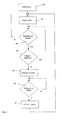
- FIG. 3 shows an example of a flow chart for the method according to the invention shown.
- Timer started.
- step 303 there is a regular query as to whether a Control element of control unit 2 was actuated. Became a control pressed, the timer starts again. However, was not a control element actuated, a query is made in step 304 as to whether the timer has expired is, that is, whether the length of time since the last actuation of an operating element is larger than the default value. Steps 303 and 304 will be repeats continuously until step 304 determines that the timer has expired is. In this case, in step 305, the brightness of individual predetermined ones Display areas reduced. This is followed in step 306 again a query as to whether an operating element was actuated. Is that the case, in step 307 the brightness of those display areas is increased again, where the brightness was previously reduced. The process then starts again with step 302.
- the time course of the brightness is shown in FIG. 4, with three brightness levels H1, H2, H3 are shown.
- the brightness level H1 is the Brightness of the background of the display.
- H3 is the normal one Brightness of the display denotes, while H2 the reduced brightness of the Indicates display areas whose brightness automatically depends on the length of time since the last actuation of an operating element can be changed.
- the brightness levels can also be used, for example, for day and day Night operation may be different.
- the last actuation of an operating element is said to have taken place at time t1, so that the timer is started at this time.
- Individual display areas on the brightness level H2 is reduced from time t2 during the period T from the brightness.
- This time period is ended by actuating an operating element of the operating unit again at time t4.
- the time span between the times t3 and t4 will, as a rule, be considerably longer in practical operation than the time intervals T off , T on or T delay than is shown in FIG.
- the brightness of the display areas is then increased again with previously reduced brightness. This is done one during the time period T and that the brightness level of the display areas H3, whose brightness was not reduced. This process is completed at time t5.
- the last actuation of an operating element then takes place at time t6, which thus corresponds to time t1 in terms of its function. At the time t6, therefore, the delay time T closes again galvanized followed it reduce the brightness from the time t7.
- the invention was made closer using a special navigation system explained.
Landscapes
- Engineering & Computer Science (AREA)
- Physics & Mathematics (AREA)
- Computer Hardware Design (AREA)
- General Physics & Mathematics (AREA)
- Theoretical Computer Science (AREA)
- Navigation (AREA)
- Indicating Measured Values (AREA)
Abstract
Description
Die Erfindung betrifft eine elektronische Einrichtung mit einer optischen Anzeigeeinheit, die mehrere Anzeigebereiche aufweist, einer Bedieneinheit, Mitteln zur Verarbeitung von Eingabebefehlen, die über die Bedieneinheit eingegeben werden, sowie Mitteln zur Ansteuerung der Anzeigeeinheit. Weiterhin betrifft die Erfindung ein Verfahren zur Steuerung des Kontrasts einzelner Bereiche einer Anzeigeeinheit mit mehreren Anzeigebereichen zur Darstellung von Informationen.The invention relates to an electronic device with an optical display unit, which has a plurality of display areas, an operating unit, means for processing input commands entered via the control unit are, as well as means for controlling the display unit. Furthermore, the Invention a method for controlling the contrast of individual areas of a Display unit with several display areas for displaying information.
Die vorgenannte elektronische Einrichtung ist beispielsweise in Form eines Navigationssystems zum Einsatz in Kraftfahrzeugen bekannt. Bei einem solchen Navigationssystem wird die Helligkeit der optischen Anzeigeeinheit verändert, um sowohl am Tage als auch bei Fahrten in der Nacht eine optimale Informationsdarstellung zu erzielen. Beispielsweise kann vorgesehen sein, die Helligkeit der Anzeige mit Einschalten des Fahrlicht auf ein niedrigeres Niveau zu reduzieren. Es ist jedoch auch möglich, einen separaten Sensor vorzusehen, der die Intensität des Umgebungslichtes registriert und bei Unterschreiten eines Schwellwertes die Helligkeit der Anzeige reduziert.The aforementioned electronic device is, for example, in the form of a Known navigation system for use in motor vehicles. At a such navigation system, the brightness of the optical display unit changed to be optimal both during the day and when driving at night To achieve information display. For example, the Brightness of the display to a lower level when the headlights are switched on to reduce. However, it is also possible to provide a separate sensor which registers the intensity of the ambient light and falls below of a threshold value reduces the brightness of the display.
Aus der US 5,617,112 ist eine Anzeigeeinheit bekannt, die einen Lichtsensor zu Detektion der Intensität des Umgebungslichtes aufweist. Abhängig vom Signal dieses Lichtsensors werden unterschiedliche Helligkeitsniveaus der Anzeigeeinheit eingestellt. Der Übergang zwischen den Helligkeitsniveaus erfolgt dabei derart, daß die Änderungsgeschwindigkeit an die Änderungsgeschwindigkeit des Öffnungsgrades der menschlichen Pupille angepaßt ist.A display unit is known from US Pat. No. 5,617,112, which has a light sensor for detection of the intensity of the ambient light. Depending on the Different light levels of the light sensor are signal Display unit set. The transition between the brightness levels takes place in such a way that the rate of change to the rate of change is adapted to the degree of opening of the human pupil.
Bei den bekannten Anzeigeeinheiten erfolgt somit eine Anpassung der Helligkeit der Anzeige im wesentlichen zur Unterscheidung zwischen einem Tag- und Nachtbetrieb und damit zur Anpassung an die Intensität des Umgebungslichtes.In the known display units, the brightness is thus adjusted the display essentially to distinguish between a day and Night operation and thus to adapt to the intensity of the ambient light.
Gerade bei elektronischen Einrichtungen mit einer optischen Anzeigeeinheit, die in Verkehrsmitteln wie Kraftfahrzeugen, Flugzeugen oder Bahnen eingesetzt werden, können auf der Anzeigeeinheit unterschiedliche Informationen dargestellt sein. Von diesen Informationen ist häufig lediglich ein geringer Teil ständig für den Fahrer von Interesse. Andere Informationen werden dagegen nur vorübergehend benötigt oder dienen der Auswahl bestimmter Funktionen der elektronischen Einrichtung.Especially in electronic devices with an optical display unit, used in means of transport such as motor vehicles, airplanes or trains different information can be shown on the display unit be shown. Often, only a small portion of this information is available of constant interest to the driver. Other information is opposed only temporarily required or used to select certain functions the electronic device.
Aufgabe der Erfindung ist es daher, eine gattungsgemäße elektronische Einrichtung derart weiterzubilden, daß der unterschiedlichen Bedeutung der Informationen in verschiedenen Anzeigebereichen der Anzeigeeinheit insbesondere bei Nachtbetrieb Rechnung getragen wird. Eine weitere Aufgabe besteht darin, ein Verfahren zur Steuerung des Kontrasts einzelner Bereiche einer Anzeigeeinheit anzugeben.The object of the invention is therefore a generic electronic Training facility such that the different meaning of Information in various display areas of the display unit in particular is taken into account at night. Another job is a method of controlling the contrast of individual areas to indicate a display unit.
Die erstgenannte Aufgabe wird dadurch gelöst, daß bei der elektronischen Einrichtung weiterhin Mittel zur Bestimmung der Zeitdauer seit der letzten Betätigung der Bedieneinheit und zum Vergleich dieser Zeitdauer mit einem Vorgabewert sowie Mittel zur automatischen Veränderung des Kontrasts einzelner Anzeigebereiche der Anzeigeeinheit vorhanden sind und die automatische Veränderung des Kontrasts einzelner Anzeigebereiche der Anzeigeeinheit in Abhängigkeit vom Ergebnis des Vergleichs der Zeitdauer seit der letzten Betätigung der Bedieneinheit mit dem Vorgabewert erfolgt.The first object is achieved in that in the electronic Establishment continues to provide means to determine the length of time since the last Actuation of the control unit and to compare this time period with a Default value and means for automatically changing the contrast individual display areas of the display unit are available and the automatic Change the contrast of individual display areas of the display unit depending on the result of the comparison of the length of time since the last The control unit is operated with the default value.
Dabei kann generell eine Reduzierung des Kontrasts einzelner Anzeigebereiche durch Annähern der Helligkeit oder der Farbe der dargestellten Zeichen, Symbole oder dgl. an die Helligkeit oder Farbe des Hintergrundes erreicht werdenThis can generally reduce the contrast of individual display areas by approximating the brightness or color of the displayed characters, Symbols or the like reached the brightness or color of the background become
Bei der erfindungsgemäßen Einrichtung ist somit nicht wie beim Vorbekannten lediglich eine Änderung der Helligkeit der gesamten Anzeigeeinheit zur Anpassung an den Tag- oder Nachtbetrieb vorgesehen. Vielmehr ist vorgesehen, daß der Kontrast einzelner Bereiche, die beispielsweise während der Fahrt von untergeordnetem Interesse sind, automatisch verändert wird. Als Kriterium hierfür wird die Zeitdauer seit der letzten Betätigung der Bedieneinheit herangezogen. Diese Zeitdauer wird mit einem Vorgabewert verglichen. Übersteigt die Zeitdauer seit der letzten Betätigung der Bedieneinheit den Vorgabewert, so wird der Kontrast einzelner Anzeigebereiche der Anzeigeeinheit verändert. In der Regel wird hierbei der Kontrast von weniger wichtigen Anzeigebereichen reduziert.The device according to the invention is therefore not like the previously known just a change in the brightness of the entire display unit for adjustment intended for day or night operation. Rather, it is provided that the contrast of individual areas that, for example, while driving from are of minor interest, is automatically changed. As a criterion the length of time since the last actuation of the control unit is used. This time period is compared with a default value. exceeds the length of time since the control unit was last operated, the default value, so the contrast of individual display areas of the display unit is changed. In Usually the contrast of less important display areas reduced.
Handelt es sich bei der elektronischen Einrichtung beispielsweise um einen Bordcomputer eines Kraftfahrzeuges, so kann nach Ablauf einer bestimmten Zeitspanne der Kontrast des Bereichs, in dem der Wochentag oder das Datum ausgegeben wird, reduziert werden, da diese Informationen vom Fahrer nicht fortlaufend benötigt werden.For example, if the electronic device is one On-board computer of a motor vehicle, after a certain time Period of time the contrast of the area in which the day of the week or the date is reduced because this information is not provided by the driver continuously needed.
Im Falle eines Navigationssystems können auf der Anzeigeeinheit beispielsweise eine Kartendarstellung mit der aktuellen Fahrzeugposition, Fahrtrichtungshinweise sowie weitere Bereiche vorhanden sein, bei deren Anwahl über die Bedieneinheit zusätzliche Informationen ausgegeben werden oder der Zielort eingegeben werden kann. Auch diese letztgenannten Funktionen werden während der Fahrt nicht ständig benötigt, während andererseits die Kartendarstellung und/oder die Anzeige der Fahrtrichtungshinweise von ständigem Interesse für den Fahrer ist. Um insbesondere bei Nachtfahrten eine bessere Unterscheidung für den Fahrer zwischen diesen für ihn ständig wichtigen und den weniger interessierenden Bereichen zu erhalten, kann erfindungsgemäß der Kontrast der letztgenannten nach Ablauf einer bestimmten Zeitdauer nach einer Eingabe über die Bedieneinheit automatisch reduziert werden.In the case of a navigation system, for example, on the display unit a map with the current vehicle position, direction of travel as well as other areas are available when selecting them via the control unit can output additional information or the Destination can be entered. These latter functions too are not constantly needed while driving, while the Map display and / or the display of the direction of travel from constant interest for the driver. In order to achieve a better distinction for the driver between them for him all the time important and less interesting areas according to the invention the contrast of the latter after the expiration of a certain one Duration automatically reduced after an entry via the control unit become.
In einer weiteren Ausbildung der Erfindung ist vorgesehen, daß nach einem erneuten Betätigen der Bedieneinheit automatisch eine Erhöhung des Kontrasts der Anzeigebereiche erfolgt, deren Kontrast zuvor reduziert wurde. Hierdurch ist es möglich, jederzeit wieder eine klare und deutliche Erkennbarkeit aller Anzeigebereiche zu erhalten. Will der Fahrer beispielsweise bei einem Navigationssystem einen neuen Zielort eingeben, so werden durch Betätigung einer Taste der Bedieneinheit beispielsweise die entsprechenden zuvor abgedunkelten Anzeigebereiche wieder auf normale Helligkeit gegenüber einem dunkleren Hintergrund angehoben, so daß eine gute Lesbarkeit der relevanten Informationen auf der Anzeigeeinheit gewährleistet ist.In a further embodiment of the invention it is provided that after a pressing the control unit again automatically increases the contrast the display areas occur, the contrast of which was previously reduced. This makes it possible to see clearly again at any time all display areas. For example, if the driver wants one Navigation system to enter a new destination, by pressing a button on the control unit, for example, the corresponding previously darkened display areas back to normal brightness on a darker background so that the readability of the relevant information on the display unit is guaranteed.
Die Änderung des Kontrasts einzelner Anzeigebereiche kann auf verschiedene Weise erfolgen, abhängig von der Darstellungsart der Anzeigeeinheit. Bei der Darstellung von Zeichen oder Symbolen auf Anzeigeeinheiten, die beispielsweise als LCD-Anzeigen ausgebildet sein können, wird im allgemeinen zwischen Negativ- und Positivdarstellung unterschieden. Bei der Positivdarstellung sind die dargestellten Zeichen und Symbole dunkler als der Hintergrund der Anzeigeeinheit. Bei der Negativdarstellung ist es umgekehrt. Daraus ergibt sich, daß bei einer Anzeigeeinheit mit Positivdarstellung eine Reduzierung des Kontrasts dadurch erreicht werden kann, daß die Helligkeit der Zeichen oder Symbole erhöht und damit der Hintergrundhelligkeit angepaßt wird. Bei einer Anzeigeeinheit mit Negativdarstellung wird dagegen zur Reduzierung des Kontrasts die Helligkeit der Zeichen und Symbole reduziert werden und sich der geringeren Helligkeit des Hintergrunds annähern. Eine Anzeigeeinheit kann sowohl Bereiche mit Positiv- als auch mit Negativdarstellung aufweisen. Eine Reduzierung des Kontrasts kann daher prinzipiell auch dadurch erfolgen, daß die Helligkeit des Hintergrunds einzelner Anzeigebereiche an die Helligkeit der Zeichen und Symbole in diesem Anzeigebereich angepaßt wird.The change in the contrast of individual display areas can be different Depending on the type of representation of the display unit. In the Representation of characters or symbols on display units, for example can be designed as LCD displays, is generally between Distinguished between negative and positive presentation. With the positive display the characters and symbols shown are darker than the background of the Display unit. The reverse is true for the negative display. It follows is that in a display unit with positive display a reduction in Contrast can be achieved in that the brightness of the characters or Symbols are increased and the background brightness is adjusted accordingly. At a Display unit with negative display, however, is used to reduce the Contrast the brightness of the signs and symbols can be reduced and the approach the lower brightness of the background. A display unit can have both positive and negative areas. A In principle, the contrast can therefore also be reduced in that the brightness of the background of individual display areas to the brightness of the Characters and symbols in this display area is adjusted.
Bei Anzeigeeinheiten mit farbiger Darstellung von Zeichen und Symbolen auf einem andersfarbigen Hintergrund ist es darüber hinaus möglich, den Kontrast durch eine Farbänderung des Hintergrundes oder der Zeichen oder Symbole zu verändern. Erfolgt beispielsweise die Darstellung der Zeichen oder Symbole im Normalbetrieb in roter Farbe auf einem blauen Hintergrund, so kann zur Reduzierung des Kontrasts die Darstellung der Zeichen oder Symbole in einem Blauton erfolgen, der sich nur wenig vom Hintergrund unterscheidet. In diesem Falle erfolgt die Reduzierung des Kontrasts alleine über eine Farbänderung ohne Änderung der Helligkeit. Weiterhin sind zur Reduzierung des Kontrasts auch Kombinationen von Farb- und Helligkeitsänderungen möglich.For display units with colored display of characters and symbols a different colored background it is also possible to change the contrast by changing the color of the background or the characters or symbols change. For example, the characters or symbols are displayed in the Normal operation in red on a blue background Reduce the contrast of the representation of the characters or symbols in one Blue tone, which differs only slightly from the background. In this If the contrast is reduced, this is done solely by changing the color without changing the brightness. Furthermore, to reduce the contrast combinations of color and brightness changes are also possible.
In den nachfolgenden Ausführungen wird zur Vereinfachung im wesentlichen von einer monochromen Anzeigeeinheit mit Negativdarstellung ausgegangen, ohne daß hierin eine Beschränkung zu sehen ist.For simplification, the following explanations will essentially be: assumed a monochrome display unit with a negative display, without any limitation.
Um eine Irritierung des Fahrers durch eine plötzliche Änderung der Helligkeit einzelner Anzeigebereiche auszuschließen, ist in einer besonderen Ausführungsform vorgesehen, daß die Reduzierung und/oder die Erhöhung der Helligkeit bzw. des Kontrasts allmählich erfolgt, beispielsweise wie in der US 5,617,112 beschrieben. Zur Anpassung an die Fähigkeiten des menschlichen Auges kann dies insbesondere derart erfolgen, daß die Reduzierung der Helligkeit langsamer erfolgt als die Erhöhung der Helligkeit. To irritate the driver due to a sudden change in brightness Excluding individual display areas is in a special embodiment provided that the reduction and / or increase in Brightness or contrast takes place gradually, for example as in the US 5,617,112. To adapt to the capabilities of the human Eye this can be done in particular in such a way that the reduction of Brightness is slower than the increase in brightness.
Bei den erfindungsgemäß mit geringerem Kontrast dargestellten Anzeigebereichen kann es sich je nach Art der elektronischen Einrichtung um Bereiche unterschiedlichster Funktion handeln. Beispielsweise können diese Anzeigebereiche Auswahlmenüs oder Eingabefelder enthalten. Im Falle eines Navigationssystems ist es insbesondere weiterhin auch möglich, Straßen einer untergeordneten Kategorie, die für die Orientierung von geringerem Interesse sind, in der Kartendarstellung in der Helligkeit automatisch zu reduzieren. Beispielsweise können hierbei bei einer reinen Autobahnfahrt untergeordnete Straßen, die keine Autobahnen sind, automatisch mit geringerer Helligkeit dargestellt werden.In the display areas shown according to the invention with a lower contrast There may be areas depending on the type of electronic device act in a wide variety of functions. For example, these display areas Selection menus or input fields included. In the case of a navigation system In particular, it is still possible to subordinate streets Category that are of less interest for orientation automatically reduce the brightness in the map display. For example Subordinate roads can be that are not highways are automatically displayed with lower brightness become.
Weiterhin kann die erfindungsgemäße Veränderung des Kontrasts einzelner Anzeigebereiche auch mit einer generellen Veränderung der Helligkeit der Anzeige in Abhängigkeit vom Umgebungslicht bzw. der Tageszeit erfolgen. Insbesondere kann z. B. die automatische Veränderung des Kontrasts einzelner Anzeigebereiche nur bei eingeschaltetem Fahrlicht des Kraftfahrzeuges erfolgen. In diesem Fall wird bei einer Nachtfahrt beispielsweise eine Überflutung des Fahrers mit zu vielen optischen Reizen vermindert.Furthermore, the change in contrast according to the invention can be individual Display areas also with a general change in the brightness of the Display depending on the ambient light or the time of day. In particular, e.g. B. the automatic change of contrast of individual Display areas only when the vehicle headlights are switched on respectively. In this case, for example, there will be a flood when driving at night of the driver with too many visual stimuli.
Ein erfindungsgemäßes Verfahren zur Steuerung des Kontrasts einzelner Bereiche einer Anzeigeeinheit mit mehreren Anzeigebereichen zur Darstellung von Informationen weist die folgenden Verfahrensschritte auf:
- Starten eines Zeitgebers nach Abschluß eines Bedienvorgangs an einer mit der Anzeigeeinheit unmittelbar oder mittelbar verbundenen Bedieneinheit,
- Vergleichen des Zeitgebersignals mit einem Vorgabewert
- Reduzieren des Kontrasts einzelner Anzeigebereiche der Anzeigeeinheit, wenn das Zeitgebersignal den Vorgabewert überschreitet.
- Starting a timer after completion of an operating process on an operating unit directly or indirectly connected to the display unit,
- Compare the timer signal with a default value
- Reduce the contrast of individual display areas of the display unit when the timer signal exceeds the preset value.
Die Erfindung wird nachfolgend anhand der Zeichnung und eines Ausführungsbeispiels mit einer Anzeigeeinheit mit Negativdarstellung näher erläutert. Es zeigen:
Figur 1- die Komponenten eines Navigationssystems für Kraftfahrzeuge
Figur 2- die Anzeigeeinheit eines solchen Navigationssystems
Figur 3- einen Ablaufplan einer Ausführungsform des erfindungsgemäßen Verfahrens
- Figur 4
- die zeitliche Änderung der Helligkeit einzelner Anzeigebereiche
- Figure 1
- the components of a navigation system for motor vehicles
- Figure 2
- the display unit of such a navigation system
- Figure 3
- a flowchart of an embodiment of the method according to the invention
- Figure 4
- the temporal change in the brightness of individual display areas
In Figur 1 sind die Komponenten eines Navigationssystems für Kraftfahrzeuge
schematisch dargestellt. Zentraler Bestandteil des Navigationssystems ist die
Recheneinheit (CPU) 1. Mit der CPU 1 ist eine Bedieneinheit 2 verbunden, über
die beispielsweise der Zielort eingegeben oder ausgewählt werden kann. Die
Bedieneinheit 2 kann im gleichen Gehäuse wie die CPU 1 untergebracht sein,
jedoch kann die Bedieneinheit 2 auch als Fernbedienung ausgebildet sein, die
mit der CPU 1 beispielsweise über eine optische Schnittstelle oder eine
Funkschnittstelle in Verbindung steht. Mit der CPU 2 ist eine optische Ausgabeeinheit
3 verbunden, über die Zielführungsinformationen und sonstige
Informationen ausgegeben werden. Die Zielführungsinformationen können
weiterhin über einen Lautsprecher 4 akustisch ausgegeben werden. Die CPU 1
ist ferner mit einer Datenbank 5 verbunden, die die Landkartendaten enthält.
Die Landkartendaten sind beispielsweise auf einer CD-ROM abgespeichert. In
diesem Falle enthält das Navigationssystem ein CD-ROM-Laufwerk, das mit
der CPU 1 verbunden ist. Anhand der Landkartendaten kann von der CPU 1
bei bekanntem Start- und Zielort in bekannter Weise eine Berechnung der
optimalen Route durchgeführt werden, die dann über die optische Ausgabeeinheit
3 ausgegeben werden kann. Zur Bestimmung der aktuellen Fahrzeugposition
enthält das Navigationssystem ferner einen Empfänger 6 zum Empfang
von Satellitennavigationssignalen. Um eine satellitenunabhängige Positionsbestimmung
durchführen zu können, enthält das Navigationssystem ferner einen
Richtungssensor 7 und einen Wegsensor 8, die ebenfalls mit der CPU 1
verbunden sind, so daß mit Hilfe eines geeigneten Programmes mit diesen
Signalen eine Positionsbestimmung möglich ist. Ein solches Navigationssystem
ist bekannt und bildet nicht den Inhalt der vorliegenden Erfindung. Das in Figur
1 dargestellte Navigationssystem wird hier lediglich beispielhaft erläutert. Die
Erfindung ist auch mit anderen Ausgestaltungen von Navigationssystemen
einsetzbar, beispielsweise auch mit sogenannten Offboard-Navigationssystemen,
bei denen die Zielführungsinformationen von außerhalb
in das Fahrzeug übermittelt werden.In Figure 1 are the components of a navigation system for motor vehicles
shown schematically. The central component of the navigation system is the
Computing unit (CPU) 1. An
In Figur 2 ist die Anzeigeeinheit des Navigationssystems näher dargestellt.
Abweichend von der Darstellung wird in der nachfolgenden Beschreibung von
einer Anzeigeeinheit mit Negativdarstellung, d.h. helle Symbole auf dunklem
Hintergrund, ausgegangen. Die Ausgabeeinheit 3 enthält einen ersten Bereich
mit einer in diesem Fall schematisierten Kartendarstellung, die die Straßen 9,
10, 11 sowie die Fahrzeugposition 12 zeigt. In einem weiteren Bereich wird
durch einen Pfeil 13 die Fahrtrichtung, bzw. ein bevorstehendes Abbiegen
angezeigt. Bei der Kartendarstellung und/oder der Pfeildarstellung handelt es
sich um Informationen die für den Fahrer während der Fahrt zur Zielführung
ständig von Interesse sind. Die Anzeigeeinheit 3 weist weitere Anzeigebereiche
14, 15, 16, 17, 18 auf. Im Anzeigebereich 18 wird beispielsweise der aktuelle
Wochentag, das aktuelle Datum und die Uhrzeit angezeigt. Die Anzeigebereiche
14, 15, 16, 17 können über die Bedieneinheit angewählt werden. Bei
Anwahl des Anzeigebereichs 14 wird beispielsweise die Eingabe eines Zielortes
ermöglicht. Bei Anwahl des Bereichs 15 wird eine vollständige Routenkarte
auf der Anzeigeeinheit 3 dargestellt. Bei Anwahl des Bereichs 16 wird eine
neue Routenberechnung vorgenommen und bei Anwahl des Bereichs 17
werden weitere Informationen auf der Anzeigeeinheit 3 dargestellt. Durch
Auswahl eines der Anzeigebereiche 14 bis 17 kann beispielsweise auch eine
weiteres Untermenü aufgerufen werden. Die Anzeigebereiche 14 bis 18 sind für
den Fahrer in der Regel nur vor oder zu Beginn einer Fahrt von Interesse,
beispielsweise um den Zielort einzugeben oder eine Routenberechnung
durchzuführen. Bei einem erfindungsgemäßen Navigationssystem werden
daher einige oder alle der Ausgabebereiche 14 bis 18 nach Ablauf einer
vorgegebenen Zeitdauer nach der letzten Eingabe über die Bedieneinheit 2 in
ihrer Helligkeit reduziert. Vorzugsweise erfolgt dies soweit, daß die Helligkeit
der in diesen Anzeigebereichen dargestellten Informationen nur noch geringfügig
über der Hintergrundhelligkeit liegt, so daß die Informationen zwar noch
erkennbar sind, aber gegenüber der Kartendarstellung deutlich in den Hintergrund
treten. Die Bestimmung der Zeitdauer seit dem Betätigen der Bedieneinheit
2 sowie der Vergleich mit einem Vorgabewert wird softwaremäßig in der
CPU 1 durchgeführt. Abhängig von diesem Vergleich liefert die CPU 1 entsprechende
Ausgangssignale für die Anzeigeeinheit 3, wobei in der Regel zwischen
der CPU 1 und der Anzeigeeinheit 3 noch entsprechende Treiber oder dergleichen
zwischengeschaltet sind.The display unit of the navigation system is shown in more detail in FIG.
Deviating from the illustration, the following description of
a display unit with negative display, i.e. bright symbols on dark
Background, outgoing. The
In Figur 3 ist ein Ablaufplan für das erfindungsgemäße Verfahren beispielhaft
dargestellt. Nach einer Initialisierungsphase in Schritt 301 wird in Schritt 302 ein
Zeitgeber gestartet. Es erfolgt regelmäßig in Schritt 303 eine Abfrage, ob ein
Bedienelement der Bedieneinheit 2 betätigt wurde. Wurde ein Bedienelement
betätigt, so startet der Zeitgeber von neuem. Wurde dagegen kein Bedienelement
betätigt, so erfolgt in Schritt 304 eine Abfrage, ob der Zeitgeber abgelaufen
ist, das heißt, ob die Zeitdauer seit dem letzten Betätigen eines Bedienelementes
größer ist als der Vorgabewert. Die Schritte 303 und 304 werden
ständig wiederholt bis in Schritt 304 festgestellt wird, daß der Zeitgeber abgelaufen
ist. In diesem Fall wird in Schritt 305 die Helligkeit einzelner vorbestimmter
Anzeigebereiche reduziert. Anschließend erfolgt in Schritt 306
wiederum eine Abfrage, ob ein Bedienelement betätigt wurde. Ist dies der Fall,
so wird in Schritt 307 die Helligkeit derjenigen Anzeigebereiche wieder erhöht,
bei denen die Helligkeit zuvor reduziert wurde. Das Verfahren startet anschließend
erneut mit Schritt 302.FIG. 3 shows an example of a flow chart for the method according to the invention
shown. After an initialization phase in
In Figur 4 ist der zeitliche Verlauf der Helligkeit dargestellt, wobei drei Helligkeitsniveaus H1, H2, H3 eingezeichnet sind. Das Helligkeitsniveau H1 ist die Helligkeit des Hintergrundes der Anzeigendarstellung. Mit H3 ist die normale Helligkeit der Anzeige bezeichnet, während H2 die reduzierte Helligkeit der Anzeigebereiche bezeichnet, deren Helligkeit automatisch in Abhängigkeit von der Zeitdauer seit der letzten Betätigung eines Bedienelements veränderbar ist. Die Helligkeitsniveaus können zusätzlich beispielsweise noch für Tag- und Nachtbetrieb unterschiedlich sein.The time course of the brightness is shown in FIG. 4, with three brightness levels H1, H2, H3 are shown. The brightness level H1 is the Brightness of the background of the display. With H3 is the normal one Brightness of the display denotes, while H2 the reduced brightness of the Indicates display areas whose brightness automatically depends on the length of time since the last actuation of an operating element can be changed. The brightness levels can also be used, for example, for day and day Night operation may be different.
Zum Zeitpunkt t1 soll die letzte Betätigung eines Bedienelements erfolgt sein, so daß zu diesem Zeitpunkt der Zeitgeber gestartet wird. Der Zeitgeber ist zum Zeitpunkt t2, also nach der Zeitspanne Tverz, die dem Vorgabewert entspricht, abgelaufen. Vom Zeitpunkt t2 an wird während der Zeitspanne Taus die Helligkeit einzelner Anzeigebereiche auf das Helligkeitsniveau H2 reduziert. Zwischen den Zeitpunkten t3 und t4 liegt somit ein Betriebszustand mit zwei konstanten, unterschiedlichen Helligkeitsniveaus für verschiedene Anzeigebereiche vor. Diese Zeitspanne wird mit einer erneuten Betätigung eines Bedienelements der Bedieneinheit zum Zeitpunkt t4 beendet. Die Zeitspanne zwischen den Zeitpunkten t3 und t4 wird im praktischen Betrieb im Vergleich zu den Zeitintervallen Taus, Tein oder Tverz in der Regel wesentlich größer sein als aus Vereinfachungsgründen in Figur 4 dargestellt. Nach dem erneuten Betätigen eines Bedienelements zum Zeitpunkt t4 wird anschließend die Helligkeit der Anzeigebereiche mit zuvor reduzierter Helligkeit wieder angehoben. Dies erfolgt während der Zeitspanne Tein und zwar auf das Helligkeitsniveau H3 der Anzeigebereiche, deren Helligkeit nicht reduziert wurde. Dieser Vorgang ist zum Zeitpunkt t5 abgeschlossen. Das letztmalige Betätigen eines Bedienelements erfolgt dann zum Zeitpunkt t6, der damit von seiner Funktion her dem Zeitpunkt t1 entspricht. An den Zeitpunkt t6 schließt sich daher wieder die Verzögerungszeitspanne Tverz mit daran anschließender Verringerung der Helligkeit ab dem Zeitpunkt t7 an.The last actuation of an operating element is said to have taken place at time t1, so that the timer is started at this time. The timer expired at time t2, that is to say after the time period T delay which corresponds to the preset value. Individual display areas on the brightness level H2 is reduced from time t2 during the period T from the brightness. Between times t3 and t4, there is an operating state with two constant, different brightness levels for different display areas. This time period is ended by actuating an operating element of the operating unit again at time t4. The time span between the times t3 and t4 will, as a rule, be considerably longer in practical operation than the time intervals T off , T on or T delay than is shown in FIG. After actuating an operating element again at time t4, the brightness of the display areas is then increased again with previously reduced brightness. This is done one during the time period T and that the brightness level of the display areas H3, whose brightness was not reduced. This process is completed at time t5. The last actuation of an operating element then takes place at time t6, which thus corresponds to time t1 in terms of its function. At the time t6, therefore, the delay time T closes again galvanized followed it reduce the brightness from the time t7.
Die Erfindung wurde anhand eines speziellen Navigationssystems näher erläutert. Jedoch ist weder die spezielle Ausgestaltung des Navigationssystems noch die im Ausführungsbeispiel genannte spezielle Art der Informationen auf der Ausgabeeinheit als Beschränkung anzusehen. Vielmehr kann es sich um jede elektronische Einrichtung mit optischer Anzeigefunktion handeln, bei der eine ähnliche optische Gewichtung unterschiedlicher Anzeigebereiche gewünscht wird.The invention was made closer using a special navigation system explained. However, neither is the special design of the navigation system the special type of information mentioned in the exemplary embodiment the output unit as a restriction. Rather, it can be trade any electronic device with an optical display function in which a similar optical weighting of different display areas is desired becomes.
Claims (16)
Applications Claiming Priority (2)
| Application Number | Priority Date | Filing Date | Title |
|---|---|---|---|
| DE19956109A DE19956109A1 (en) | 1999-11-22 | 1999-11-22 | Electronic device with a display unit |
| DE19956109 | 1999-11-22 |
Publications (3)
| Publication Number | Publication Date |
|---|---|
| EP1102233A2 true EP1102233A2 (en) | 2001-05-23 |
| EP1102233A3 EP1102233A3 (en) | 2001-05-30 |
| EP1102233B1 EP1102233B1 (en) | 2009-06-24 |
Family
ID=7929898
Family Applications (1)
| Application Number | Title | Priority Date | Filing Date |
|---|---|---|---|
| EP00123452A Expired - Lifetime EP1102233B1 (en) | 1999-11-22 | 2000-11-06 | Electronic device with a display element |
Country Status (2)
| Country | Link |
|---|---|
| EP (1) | EP1102233B1 (en) |
| DE (2) | DE19956109A1 (en) |
Cited By (1)
| Publication number | Priority date | Publication date | Assignee | Title |
|---|---|---|---|---|
| EP1868169A1 (en) * | 2006-06-09 | 2007-12-19 | Aruze Corporation | Gaming machine |
Families Citing this family (2)
| Publication number | Priority date | Publication date | Assignee | Title |
|---|---|---|---|---|
| DE10144752A1 (en) * | 2001-09-11 | 2003-03-27 | Volkswagen Ag | Optical information representation method for automobile with classification and filtering of information supplied to display device |
| DE102004019329B4 (en) * | 2004-04-21 | 2016-11-03 | BSH Hausgeräte GmbH | Dishwasher with optical operating display |
Citations (3)
| Publication number | Priority date | Publication date | Assignee | Title |
|---|---|---|---|---|
| US5598565A (en) | 1993-12-29 | 1997-01-28 | Intel Corporation | Method and apparatus for screen power saving |
| US5617112A (en) | 1993-12-28 | 1997-04-01 | Nec Corporation | Display control device for controlling brightness of a display installed in a vehicular cabin |
| WO1999053472A1 (en) | 1998-04-15 | 1999-10-21 | Cambridge Display Technology Ltd. | Display control device with modes for reduced power consumption |
Family Cites Families (11)
| Publication number | Priority date | Publication date | Assignee | Title |
|---|---|---|---|---|
| DE4012750A1 (en) * | 1990-04-21 | 1991-10-24 | Hoechst Ag | FERROELECTRIC LIQUID CRYSTAL DISPLAY WITH HIGH CONTRAST AND HIGH BRIGHTNESS |
| JPH04250489A (en) * | 1991-01-10 | 1992-09-07 | Pioneer Electron Corp | On-vehicle navigation aids |
| JPH0843811A (en) * | 1994-08-02 | 1996-02-16 | Hitachi Ltd | Liquid crystal display device |
| DE19531824A1 (en) * | 1994-10-07 | 1996-04-11 | Mannesmann Ag | Method for controlling a display device for route guidance of a vehicle |
| US5818553A (en) * | 1995-04-10 | 1998-10-06 | Norand Corporation | Contrast control for a backlit LCD |
| WO1997003432A1 (en) * | 1995-07-13 | 1997-01-30 | Motorola Inc. | Method and apparatus for backlighting a display for different times in a battery powered device |
| JPH09123848A (en) * | 1995-11-06 | 1997-05-13 | Toyota Motor Corp | Vehicular information display device |
| US6271813B1 (en) * | 1996-08-30 | 2001-08-07 | Lear Automotive Dearborn, Inc. | Voltage control for adjusting the brightness of a screen display |
| JP2891955B2 (en) * | 1997-02-14 | 1999-05-17 | 日本電気移動通信株式会社 | LCD display device |
| DE19755470A1 (en) * | 1997-02-24 | 1998-09-24 | Marius Dipl Ing Tegethoff | Display system for vehicles |
| JP3700387B2 (en) * | 1998-04-15 | 2005-09-28 | セイコーエプソン株式会社 | Liquid crystal display device, driving method of liquid crystal display device, and electronic apparatus |
-
1999
- 1999-11-22 DE DE19956109A patent/DE19956109A1/en not_active Withdrawn
-
2000
- 2000-11-06 DE DE50015671T patent/DE50015671D1/en not_active Expired - Lifetime
- 2000-11-06 EP EP00123452A patent/EP1102233B1/en not_active Expired - Lifetime
Patent Citations (3)
| Publication number | Priority date | Publication date | Assignee | Title |
|---|---|---|---|---|
| US5617112A (en) | 1993-12-28 | 1997-04-01 | Nec Corporation | Display control device for controlling brightness of a display installed in a vehicular cabin |
| US5598565A (en) | 1993-12-29 | 1997-01-28 | Intel Corporation | Method and apparatus for screen power saving |
| WO1999053472A1 (en) | 1998-04-15 | 1999-10-21 | Cambridge Display Technology Ltd. | Display control device with modes for reduced power consumption |
Cited By (1)
| Publication number | Priority date | Publication date | Assignee | Title |
|---|---|---|---|---|
| EP1868169A1 (en) * | 2006-06-09 | 2007-12-19 | Aruze Corporation | Gaming machine |
Also Published As
| Publication number | Publication date |
|---|---|
| EP1102233A3 (en) | 2001-05-30 |
| DE50015671D1 (en) | 2009-08-06 |
| DE19956109A1 (en) | 2001-05-23 |
| EP1102233B1 (en) | 2009-06-24 |
Similar Documents
| Publication | Publication Date | Title |
|---|---|---|
| EP0540570B1 (en) | Process for carrying out a variable dialogue with technical equipment | |
| DE102008045406B4 (en) | On-board display device and display method for an on-board display device | |
| DE4307367A1 (en) | Display and control device, in particular for motor vehicles | |
| DE19958791B4 (en) | Navigation system with several display devices | |
| EP1031456B1 (en) | Procedure and device to support a motor vehicle user when operating vehicle components | |
| DE19903093C2 (en) | Device for displaying vehicle data in a motor vehicle | |
| EP1102037A1 (en) | Navigation system with improved object selection | |
| DE19646104C1 (en) | Device for selecting and displaying speeds | |
| DE102006029692A1 (en) | Method for adjusting blocking of navigation and audio system functions while driving | |
| DE102007018072A1 (en) | A display device for a vehicle for displaying information concerning the operation of the vehicle and methods for displaying this information | |
| WO2019110056A1 (en) | Display device for a driving system for automated driving for displaying the active automated driving mode | |
| EP0796765A2 (en) | Procedure for changing adjustable functions in a vehicle | |
| DE102006012195A1 (en) | Control method for the display mode of an electronic device | |
| DE102007018075A1 (en) | Parameter e.g. automatic speed control system' ideal velocity, indicating method for motor vehicle, involves highlightly representing dial in sections, where one section is not highlightly represented based on chart' initial value | |
| EP1110815A2 (en) | Process for automatically controlling the exterior lighting of a vehicle | |
| DE3001470A1 (en) | Travel data computer for vehicles - has keyboard for entering data and selecting which data is displayed on 7-segment display | |
| DE19822919A1 (en) | Navigation system for road vehicles | |
| EP1214563B1 (en) | Representing the system state of a speed and distance control system | |
| DE102007018073A1 (en) | A method of displaying a digital map in a vehicle and display device therefor | |
| EP1102233B1 (en) | Electronic device with a display element | |
| DE60101718T2 (en) | Information system and corresponding method for a motor vehicle | |
| DE10358928A1 (en) | Control system for a device carried in a vehicle | |
| DE102008038585A1 (en) | Assistance system, particularly for motor vehicle, has avionics, display device for displaying information controlled by avionics, input device and memory element | |
| DE102015000402A1 (en) | Motor vehicle and method for operating a cruise control system | |
| EP1128261A2 (en) | Display arrangement with at least two display modules |
Legal Events
| Date | Code | Title | Description |
|---|---|---|---|
| PUAI | Public reference made under article 153(3) epc to a published international application that has entered the european phase |
Free format text: ORIGINAL CODE: 0009012 |
|
| PUAL | Search report despatched |
Free format text: ORIGINAL CODE: 0009013 |
|
| AK | Designated contracting states |
Kind code of ref document: A2 Designated state(s): DE FR GB |
|
| AX | Request for extension of the european patent |
Free format text: AL;LT;LV;MK;RO;SI |
|
| AK | Designated contracting states |
Kind code of ref document: A3 Designated state(s): AT BE CH CY DE DK ES FI FR GB GR IE IT LI LU MC NL PT SE TR |
|
| AX | Request for extension of the european patent |
Free format text: AL;LT;LV;MK;RO;SI |
|
| 17P | Request for examination filed |
Effective date: 20010619 |
|
| RAP1 | Party data changed (applicant data changed or rights of an application transferred) |
Owner name: SIEMENS AKTIENGESELLSCHAFT |
|
| AKX | Designation fees paid |
Free format text: DE FR GB |
|
| 17Q | First examination report despatched |
Effective date: 20071010 |
|
| RAP1 | Party data changed (applicant data changed or rights of an application transferred) |
Owner name: CONTINENTAL AUTOMOTIVE GMBH |
|
| GRAP | Despatch of communication of intention to grant a patent |
Free format text: ORIGINAL CODE: EPIDOSNIGR1 |
|
| GRAS | Grant fee paid |
Free format text: ORIGINAL CODE: EPIDOSNIGR3 |
|
| GRAA | (expected) grant |
Free format text: ORIGINAL CODE: 0009210 |
|
| AK | Designated contracting states |
Kind code of ref document: B1 Designated state(s): DE FR GB |
|
| REG | Reference to a national code |
Ref country code: GB Ref legal event code: FG4D Free format text: NOT ENGLISH |
|
| REF | Corresponds to: |
Ref document number: 50015671 Country of ref document: DE Date of ref document: 20090806 Kind code of ref document: P |
|
| PLBE | No opposition filed within time limit |
Free format text: ORIGINAL CODE: 0009261 |
|
| STAA | Information on the status of an ep patent application or granted ep patent |
Free format text: STATUS: NO OPPOSITION FILED WITHIN TIME LIMIT |
|
| 26N | No opposition filed |
Effective date: 20100325 |
|
| PGFP | Annual fee paid to national office [announced via postgrant information from national office to epo] |
Ref country code: GB Payment date: 20121120 Year of fee payment: 13 |
|
| GBPC | Gb: european patent ceased through non-payment of renewal fee |
Effective date: 20131106 |
|
| PG25 | Lapsed in a contracting state [announced via postgrant information from national office to epo] |
Ref country code: GB Free format text: LAPSE BECAUSE OF NON-PAYMENT OF DUE FEES Effective date: 20131106 |
|
| REG | Reference to a national code |
Ref country code: DE Ref legal event code: R084 Ref document number: 50015671 Country of ref document: DE |
|
| REG | Reference to a national code |
Ref country code: DE Ref legal event code: R084 Ref document number: 50015671 Country of ref document: DE Effective date: 20150327 |
|
| REG | Reference to a national code |
Ref country code: FR Ref legal event code: PLFP Year of fee payment: 16 |
|
| REG | Reference to a national code |
Ref country code: FR Ref legal event code: PLFP Year of fee payment: 17 |
|
| PGFP | Annual fee paid to national office [announced via postgrant information from national office to epo] |
Ref country code: DE Payment date: 20161130 Year of fee payment: 17 |
|
| REG | Reference to a national code |
Ref country code: FR Ref legal event code: PLFP Year of fee payment: 18 |
|
| PGFP | Annual fee paid to national office [announced via postgrant information from national office to epo] |
Ref country code: FR Payment date: 20171121 Year of fee payment: 18 |
|
| REG | Reference to a national code |
Ref country code: DE Ref legal event code: R119 Ref document number: 50015671 Country of ref document: DE |
|
| PG25 | Lapsed in a contracting state [announced via postgrant information from national office to epo] |
Ref country code: DE Free format text: LAPSE BECAUSE OF NON-PAYMENT OF DUE FEES Effective date: 20180602 |
|
| PG25 | Lapsed in a contracting state [announced via postgrant information from national office to epo] |
Ref country code: FR Free format text: LAPSE BECAUSE OF NON-PAYMENT OF DUE FEES Effective date: 20181130 |