EP1102136B1 - Vorrichtung zum Aufsetzen einer Schutzkappe aus hartem Material auf den Mittelteil einer Uhr - Google Patents
Vorrichtung zum Aufsetzen einer Schutzkappe aus hartem Material auf den Mittelteil einer Uhr Download PDFInfo
- Publication number
- EP1102136B1 EP1102136B1 EP99122881A EP99122881A EP1102136B1 EP 1102136 B1 EP1102136 B1 EP 1102136B1 EP 99122881 A EP99122881 A EP 99122881A EP 99122881 A EP99122881 A EP 99122881A EP 1102136 B1 EP1102136 B1 EP 1102136B1
- Authority
- EP
- European Patent Office
- Prior art keywords
- cover
- centre
- cap
- screws
- clamps
- Prior art date
- Legal status (The legal status is an assumption and is not a legal conclusion. Google has not performed a legal analysis and makes no representation as to the accuracy of the status listed.)
- Expired - Lifetime
Links
- 239000000463 material Substances 0.000 title claims description 13
- 239000013078 crystal Substances 0.000 claims description 4
- 230000000295 complement effect Effects 0.000 claims description 3
- 238000005304 joining Methods 0.000 claims description 3
- 239000002184 metal Substances 0.000 claims 1
- 238000007789 sealing Methods 0.000 claims 1
- 238000003754 machining Methods 0.000 description 5
- 230000035939 shock Effects 0.000 description 4
- 229920001971 elastomer Polymers 0.000 description 3
- 239000000806 elastomer Substances 0.000 description 3
- 239000000919 ceramic Substances 0.000 description 2
- 238000005253 cladding Methods 0.000 description 2
- 238000010276 construction Methods 0.000 description 2
- 210000005069 ears Anatomy 0.000 description 2
- 238000000227 grinding Methods 0.000 description 2
- 210000004247 hand Anatomy 0.000 description 2
- 238000004519 manufacturing process Methods 0.000 description 2
- 238000000034 method Methods 0.000 description 2
- 229910052594 sapphire Inorganic materials 0.000 description 2
- 239000010980 sapphire Substances 0.000 description 2
- 206010001488 Aggression Diseases 0.000 description 1
- 229910001369 Brass Inorganic materials 0.000 description 1
- 229910000831 Steel Inorganic materials 0.000 description 1
- 239000000853 adhesive Substances 0.000 description 1
- 238000004026 adhesive bonding Methods 0.000 description 1
- 230000001070 adhesive effect Effects 0.000 description 1
- 230000016571 aggressive behavior Effects 0.000 description 1
- 239000010951 brass Substances 0.000 description 1
- 239000011248 coating agent Substances 0.000 description 1
- 238000000576 coating method Methods 0.000 description 1
- 239000000470 constituent Substances 0.000 description 1
- 238000000151 deposition Methods 0.000 description 1
- 229910003460 diamond Inorganic materials 0.000 description 1
- 239000010432 diamond Substances 0.000 description 1
- 239000011521 glass Substances 0.000 description 1
- 230000002427 irreversible effect Effects 0.000 description 1
- 230000003647 oxidation Effects 0.000 description 1
- 238000007254 oxidation reaction Methods 0.000 description 1
- 238000005498 polishing Methods 0.000 description 1
- 239000010959 steel Substances 0.000 description 1
- 210000000707 wrist Anatomy 0.000 description 1
Images


Classifications
-
- G—PHYSICS
- G04—HOROLOGY
- G04B—MECHANICALLY-DRIVEN CLOCKS OR WATCHES; MECHANICAL PARTS OF CLOCKS OR WATCHES IN GENERAL; TIME PIECES USING THE POSITION OF THE SUN, MOON OR STARS
- G04B47/00—Time-pieces combined with other articles which do not interfere with the running or the time-keeping of the time-piece
- G04B47/04—Time-pieces combined with other articles which do not interfere with the running or the time-keeping of the time-piece with attached ornaments or amusement apparatus
- G04B47/046—Changeable decorations and parts thereof, decorations for the case which change the external appearance of the clockwork
-
- G—PHYSICS
- G04—HOROLOGY
- G04B—MECHANICALLY-DRIVEN CLOCKS OR WATCHES; MECHANICAL PARTS OF CLOCKS OR WATCHES IN GENERAL; TIME PIECES USING THE POSITION OF THE SUN, MOON OR STARS
- G04B37/00—Cases
- G04B37/0008—Cases for pocket watches and wrist watches
-
- G—PHYSICS
- G04—HOROLOGY
- G04B—MECHANICALLY-DRIVEN CLOCKS OR WATCHES; MECHANICAL PARTS OF CLOCKS OR WATCHES IN GENERAL; TIME PIECES USING THE POSITION OF THE SUN, MOON OR STARS
- G04B37/00—Cases
- G04B37/08—Hermetic sealing of openings, joints, passages or slits
- G04B37/084—Complete encasings for wrist or pocket watches without means for hermetic sealing of winding stem or crown
-
- G—PHYSICS
- G04—HOROLOGY
- G04B—MECHANICALLY-DRIVEN CLOCKS OR WATCHES; MECHANICAL PARTS OF CLOCKS OR WATCHES IN GENERAL; TIME PIECES USING THE POSITION OF THE SUN, MOON OR STARS
- G04B37/00—Cases
- G04B37/22—Materials or processes of manufacturing pocket watch or wrist watch cases
Definitions
- the present invention relates to a device for assembling a hard material cap on the upper edge of the middle part of a watch case.
- the exposed parts that is to say the ice, the middle part and the cap are the parts most exposed to external aggressions, such as scratches, shocks, oxidation, etc.
- external aggressions such as scratches, shocks, oxidation, etc.
- it eliminates or reduces the unsightly consequences of these attacks on the ice using a sapphire crystal whose manufacture is certainly delicate, but whose simple geometric shape does not involve complicated machining.
- a very hard material such as a ceramic.
- Such a material has a remarkable resistance to external attack, but has the drawbacks of being still sensitive to shocks and very poorly suited to overly complex machining. For this reason, this hard material is most often used as a cladding for an underlying structure that is easier to machine and generally much cheaper.
- the document CH 508 925 proposes to removably attach the cap to an element of the housing by providing two facing grooves between which is interposed a resilient closed ring which will be compressed during assembly. If the section of this ring is too strong, we risk breaking the cap by forcing it to the assembly; if on the contrary the section is too low the cap may turn around the middle part which can be inconvenient for the passage of the time setting rod, or unsightly if the cap is not perfectly circular.
- the document CH 568 040 proposes to radially arrange blind holes in the flat underside of the cap, to fill these holes with a readily tapable material and to screw said cap on an element of the middle part.
- the proposed solution allows to consider, if necessary, a replacement of said cap and provides a better relative positioning of the two assembled elements, but such a construction is relatively complex and the blind holes undoubtedly embrittle said cap.
- the present invention therefore aims to overcome the drawbacks of this prior art by providing a device for assembling a hard material cap on the upper edge of the middle part of a watch case or on a part integral with it. ci, said cap can be obtained with a reduced number of machining operations and can be easily replaced in case of breakage.
- the invention relates to a removable assembly device of a hard material cap on the upper edge of the middle part of a watch case closed by an ice and a bottom delimiting with a casing ring, a space for accommodating at least one movement, characterized in that it comprises a metal center whose external wall has a staircase structure complementary to the internal structure of the cap secured to said center by means of at least two screws passing through it through holes for clamping flanges housed in radial recesses formed in a vertical wall of the cap, compressing an elastomeric seal disposed between two horizontal surfaces of the stair structures, and whose thickness is sufficient to provide at least one clearance between surfaces respectively facing the bottom and the base of the cap, and the vertical wall of the center and the wall of the cap joining the base.
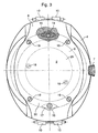
- the case 1 of a wristwatch is shown, the visible parts of which consist essentially of a cap 20 forming a middle part 4, in which a recess 5 is formed for the housing of the time-setting ring 7.
- the recess 5 comprises in its center a channel 26, visible on the figure 4 , which joins the inner surface of the cap 20 to allow the passage of the stem of the setting ring 7.
- the central portion of the cap 20 comprises, above a dial 11 provided with hour hands / minutes / seconds 13a, 13b, 13c, a sapphire crystal 3, whose fixing will be explained later.
- the cap 20 leaves, at the positions 12h-6h, below the middle part 4, an extension 8 of the bottom 2, curved outwards substantially according to the curvature of a wrist and provided with horns 10 serving fixing a bracelet (not shown). It is obvious that after fixing a bracelet this extension 8 will not be visible at all.
- the bottom 2 and the dial 11 delimit, with the casing ring 6, a housing 9 for a watch movement 29 held by two fixing screws 18 (also visible on the figure 3 ).
- the cap 20 has an oblong shape and covers, from the perimeter of the ice 3, the entire surface of the watch forming two lugs 28 extending above the extensions 8, being, like said extensions 8 curved towards the outside to form a dome.
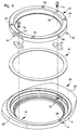
- the figure 4 is a representation in exploded perspective of the. assembly device, the different parts having the orientation in view from below represented at the figure 3 .
- the device comprises a metal center 30, an elastomer washer 12, two screws 14, 16 and two flanges 15, 17 which will allow the assembly of the cap 20.
- the inner wall of the cap has an annular stair structure formed from the base 21 by orthogonal flat surfaces 21a, 22, 22a, 23a.
- the base 21 is extended at the ears 28 by oblique extensions 24 having the same inclination as the extensions 8 of the bottom 2.
- the vertical portion 21a, joining the base 21 and parallel to the middle part 4 comprises at the ears 28 two recesses 25, 27 diametrically opposed and intended to receive the flanges 15, 17.
- these recesses are the only parts of the cap 20 which require special machining. They can for example be obtained by means of a diamond grinding, or by providing, during the manufacture of the cap of the drawers in the mold at the locations of the recesses 25, 27.
- the metal center 30 is formed of a ring whose outer surface has a stair shape, complementary to that of the cap 20, formed from the base 31, by flat surfaces 31a, 32, 32a, 33.
- the inner wall 46 of metal center 30 comprises at its base and at its upper part two annular grooves 45, 47 for receiving seals 45a, 47a respectively compressed axially against the bottom 2 and radially against the vertical edge 3a of the ice 3.
- bottom of the annular groove 47 is extended towards the inside of the casing 1 by a ring 40 which will form a flange between the spout 3b of the glass 3 and the dial 11. It is obvious that this ring 40 has only one optional character and that it could be replaced by an independent enhancement.
- the surface 33 of the metal center 30 comprises two open recesses 35, 37 which are diametrically opposed and intended to receive the flanges 15, 17.
- the recesses 35, 37 comprise in their substantially median part the axial bores 34, 36 in which will be engaged. the screws 14, 16 for fixing the flanges 15, 17.
- These clearances 35, 37 make it possible to reduce the height of the assembly device and facilitate the positioning of the center 30 above the flanges. According to a simpler embodiment, it is also possible to provide no clearance.
- the metal center 30 finally has, distributed around its periphery, four tapped holes 39 for fixing the bottom 2 by means of four screws 19, and a radial bore 38 for the passage of the crown rod 7.
- a first step from the central element formed by the metal center 30, it is possible to preassemble in a known manner all the constituent elements of the watch, ice 3, hands 13a, 13b, 13c, dial 11, circle d casing 6, movement 29 and crown 7, with the exception of the cap 20 and the bottom 2. It will also be observed, in the case where the ring 40 is replaced by an independent flange, that the metal center 30 and the circle of casing 6 can be made in one piece.
- the elastomer washer 12 is then placed on the annular surface 22 of the staircase structure of the cap 20, then the two flanges 15, 17 are engaged in the recesses 25, 27.
- the metal center 30 is then placed by positioning the clearance 35, 37 above the flanges 15, 17, and then screwed together by means of the screws 14, 16 so as to compress the washer 12 between the facing annular surfaces 22, 32 of the cap 20 and the metal center 30, and finally the bottom is screwed by means of the four screws 19.
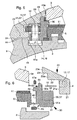
- the dimensions of the assembled elements and the thickness of the elastomer washer 12 are designed so that there are very small gaps between the internal surfaces of the cap 20 and the surfaces of the facing elements, with the exception of the surfaces 22, 32 between which is compressed the elastomeric washer 12.
- the clearance between the oblique extension 24 and the extension 8 of the bottom 2 is designated by the reference 44, that between the base 21 and the bottom 2 by the reference 41, that between the wall 21a and the corresponding wall 31a of the center 30 by the reference 41a, that between the wall 23 and the outer edge 33 of the center 20 by the reference 43, and that between the wall 23a and the edge 3a of the ice 3 by the reference 43a .
- the fixing means of the cap are two in number and are positioned under the bottom 2 positions 12h-6h, at the cap where there is the most material. Comparing the cuts of Figures 5 and 6 it will be observed that the point of the recesses 25, 27 closest to the surface of the cap 20 remains the same all around said cap, so that it is possible, according to an alternative embodiment, to consider putting more than two fixing means occupying different angular positions with respect to the axis 12h-6h. In the embodiment taken by way of example, it will be observed that the two axial bores 34, 36 and the four tapped holes 39 have an angular offset, that is to say that they are distinct and that only are apparent the screws 19 for fixing the bottom 2.
- the center 30 comprises only two tapped holes 39 for two screws 19 for fixing the bottom, the two other screws being merged with the screws 14, 16 of flange fixing 15, 17 having longer rods.
- this embodiment has the advantage of being able to replace the cap 20 without removing the bottom 2, and therefore without risk of damaging the seal 45a.
Landscapes
- Physics & Mathematics (AREA)
- General Physics & Mathematics (AREA)
- Engineering & Computer Science (AREA)
- Manufacturing & Machinery (AREA)
- Electric Clocks (AREA)
Claims (8)
- Vorrichtung zum lösbaren Anbringen einer Kappe (20) aus hartem Material an den oberen Bereich des Mittelteils (4) eines Uhrengehäuses (1), das von einem Uhrenglas (3) und einem Boden (2) verschlossen wird, der mit einem Gehäusering (6) einen Raum (9) begrenzt, um zumindest ein Uhrwerk (29) aufzunehmen, dadurch gekennzeichnet, dass sie einen Kern aus Metall (30) aufweist, dessen Außenwand einen treppenartigen Aufbau (31, 31a, 32, 32a, 33) hat, der komplementär zum Innenaufbau (21, 21a, 22, 22a, 23, 23a) der Kappe (20) ausgeführt ist, die fest mit dem Kern (30) über zumindest zwei Schrauben (14, 16) verbunden ist, welche diesen durch Bohrungen (34, 36) hindurch durchsetzen, um Flansche (15, 17) einzuklemmen, die in radialen Vertiefungen (25, 27) aufgenommen sind, welche in einer senkrechten Wand (21a) der Kappe (20) ausgebildet sind, wobei eine Elastomerdichtung (12) zusammengedrückt wird, die zwischen zwei horizontalen Flächen (22, 32) der treppenartigen Aufbauten angeordnet ist, und deren Dicke ausreicht, um zumindest zwischen den gegenüberliegenden Flächen des Bodens (2) bzw. der Basis (21) der Kappe (20) sowie der senkrechten Wand (31a) des Kerns und der auf die Basis (21) auftreffenden Wand (21a) der Kappe (20) ein jeweiliges Spiel (41, 41a) auszubilden.
- Vorrichtung nach Anspruch 1, dadurch gekennzeichnet, dass der Kern (30) ferner Freistiche (35, 37) aufweist, die sich an den Stellen der Flansche (15, 17) zur Kappe (20) hin öffnen und als Tiefe im wesentlichen die Dicke der Flansche (15, 17) haben.
- Vorrichtung nach Anspruch 1, dadurch gekennzeichnet, dass der Kern (30) ferner Gewindebohrungen (39) aufweist, die im Winkel zu den Bohrungen für die Schrauben (14, 16) der Flansche (15, 17) versetzt sind und das Befestigen des Bodens (2) mittels Schrauben (19) ermöglichen.
- Vorrichtung nach Anspruch 3, dadurch gekennzeichnet, dass zwei Schrauben (14, 16) zum Befestigen der Flansche (15, 17) auch die Befestigung des Bodens (2) ermöglichen.
- Vorrichtung nach Anspruch 1, dadurch gekennzeichnet, dass die Kappe (20) eine längliche Form hat und zwei Vertiefungen (25, 27) aufweist, die bei 12 Uhr und bei 6 Uhr positioniert sind.
- Vorrichtung nach Anspruch 1, dadurch gekennzeichnet, dass die Innenränder des Kerns (20) ferner zwei Rillen (45, 47) aufweisen, die dazu bestimmt sind, zwei Dichtungen (45a, 47a) aufzunehmen, mit denen für Dichtheit mit dem Boden (2) und dem Uhrenglas (3) gesorgt werden kann.
- Vorrichtung nach Anspruch 1, dadurch gekennzeichnet, dass der obere Bereich der Innenwand des Kerns (30) eine ringförmige Erweiterung (40) aufweist, die eine Erhebung bildet.
- Vorrichtung nach Anspruch 1, dadurch gekennzeichnet, dass der Kern (30) und der Gehäusering (6) einstückig ausgebildet sind.
Priority Applications (2)
| Application Number | Priority Date | Filing Date | Title |
|---|---|---|---|
| EP99122881A EP1102136B1 (de) | 1999-11-17 | 1999-11-17 | Vorrichtung zum Aufsetzen einer Schutzkappe aus hartem Material auf den Mittelteil einer Uhr |
| DE69940381T DE69940381D1 (de) | 1999-11-17 | 1999-11-17 | Vorrichtung zum Aufsetzen einer Schutzkappe aus hartem Material auf den Mittelteil einer Uhr |
Applications Claiming Priority (1)
| Application Number | Priority Date | Filing Date | Title |
|---|---|---|---|
| EP99122881A EP1102136B1 (de) | 1999-11-17 | 1999-11-17 | Vorrichtung zum Aufsetzen einer Schutzkappe aus hartem Material auf den Mittelteil einer Uhr |
Publications (2)
| Publication Number | Publication Date |
|---|---|
| EP1102136A1 EP1102136A1 (de) | 2001-05-23 |
| EP1102136B1 true EP1102136B1 (de) | 2009-02-04 |
Family
ID=8239417
Family Applications (1)
| Application Number | Title | Priority Date | Filing Date |
|---|---|---|---|
| EP99122881A Expired - Lifetime EP1102136B1 (de) | 1999-11-17 | 1999-11-17 | Vorrichtung zum Aufsetzen einer Schutzkappe aus hartem Material auf den Mittelteil einer Uhr |
Country Status (2)
| Country | Link |
|---|---|
| EP (1) | EP1102136B1 (de) |
| DE (1) | DE69940381D1 (de) |
Families Citing this family (6)
| Publication number | Priority date | Publication date | Assignee | Title |
|---|---|---|---|---|
| EP2107432B1 (de) | 2008-04-01 | 2011-06-29 | Montres Rado S.A. | Steuervorrichtung mit Drücker für Uhr |
| CN103343765B (zh) * | 2013-05-21 | 2015-11-11 | 张宝喜 | 用于手表、怀表和首饰的分体式金属实体连接装置 |
| CN104317181A (zh) * | 2014-08-26 | 2015-01-28 | 上海稻房投资有限公司 | 一种陶瓷背板防水手表 |
| CN107193200A (zh) * | 2017-07-19 | 2017-09-22 | 深圳市雷诺表业有限公司 | 一种可旋转快速拆卸的手表组合结构及手表 |
| CN109375490A (zh) * | 2018-11-16 | 2019-02-22 | 深圳市稳达时钟表有限公司 | 一种组合式diy手表及组合式diy手表的组装方法 |
| CN110824883B (zh) * | 2019-12-18 | 2024-07-09 | 东莞市天铭钟表有限公司 | 一种多层结构陀飞轮机械表 |
Family Cites Families (9)
| Publication number | Priority date | Publication date | Assignee | Title |
|---|---|---|---|---|
| CH311861A (fr) * | 1953-09-28 | 1955-12-15 | Derobert Jean | Montre. |
| CH517963A (fr) | 1960-10-05 | 1972-02-29 | Schlup & Cie S A | Boîte de montre |
| CH508925A (fr) | 1968-09-27 | 1971-02-15 | Piquerez Sa Ervin | Montre-bracelet comportant un écran protecteur |
| CH1766468A4 (de) | 1968-11-25 | 1970-10-30 | ||
| US3643423A (en) * | 1969-09-30 | 1972-02-22 | Piquerez Sa Ervin | Protective screen for a timepiece casing |
| FR2231042A1 (en) * | 1973-05-23 | 1974-12-20 | Chatenoud Gilles | Wrist watch with interchangeable decorative surround - covers point where bracelet is secured to watch case |
| CH568040A5 (en) | 1973-09-14 | 1975-12-15 | Weill Ernst | Tooth brush with rotatable head - enables vertical cleaning movements to be made more easily and efficiently |
| CH667966GA3 (en) * | 1987-02-18 | 1988-11-30 | Sealed wrist watch casing - has plastic body and precious metal surround with e.g. gold restricted to part of watch thickness | |
| CH684297B5 (fr) * | 1993-04-20 | 1995-02-28 | Blancpain Sa | Boîte de montre présentant une lunette amovible. |
-
1999
- 1999-11-17 DE DE69940381T patent/DE69940381D1/de not_active Expired - Lifetime
- 1999-11-17 EP EP99122881A patent/EP1102136B1/de not_active Expired - Lifetime
Also Published As
| Publication number | Publication date |
|---|---|
| EP1102136A1 (de) | 2001-05-23 |
| DE69940381D1 (de) | 2009-03-19 |
Similar Documents
| Publication | Publication Date | Title |
|---|---|---|
| EP2859412B1 (de) | System eines drehbaren aussenrings (einer uhr) | |
| EP3540523B1 (de) | Armbanduhr, die ein uhrengehäuse mit zwei zifferblättern umfasst | |
| EP3736642B1 (de) | Wasserdichtes armbanduhrgehäuse | |
| CH678254B5 (de) | ||
| EP4145230B1 (de) | Aussenring für uhr | |
| EP1680715B1 (de) | Uhr mit umkehrbarem uhrgehäuse | |
| EP1102136B1 (de) | Vorrichtung zum Aufsetzen einer Schutzkappe aus hartem Material auf den Mittelteil einer Uhr | |
| EP1065576B1 (de) | Chronographuhr aus Edelmetall mit einem ausgehöhlten Glasreif-Mittelteil | |
| EP1975747B1 (de) | Armbanduhrgehäuse | |
| CH690870A5 (fr) | Boîte de montre étanche. | |
| EP0168010A1 (de) | Uhrengehäuse | |
| EP0370356B1 (de) | Uhrengehäuse mit einem gesinterten Mittelteil | |
| EP3896535A1 (de) | Abdichtungssystem für uhrengehäuse | |
| EP0770937B1 (de) | Uhr mit einem drehbaren Ring | |
| EP3828643B1 (de) | Zifferblatt für uhr | |
| EP1241541B1 (de) | Mittels des Glasreifes zusammengebautes Uhrengehäuse | |
| EP3321749B1 (de) | Dichtungsfuge für uhrwerk | |
| EP4250020B1 (de) | Armbanduhrengehäuse mit drehbarem aussenring | |
| EP4198646B1 (de) | Wasserdichtes armbanduhrgehäuse mit fixierdichtung | |
| EP1291739B1 (de) | Wasserdichtes Uhrgehäuse und Montageverfahren für ein solches Gehäuse | |
| WO2000033144A1 (fr) | Joint d'etancheite et dispositif de commande etanche d'une piece d'horlogerie | |
| CH712378B1 (fr) | Boîte de montre à aspect visuel asymétrique | |
| CH714749B1 (fr) | Montre comprenant une boîte de montre munie de deux cadrans. | |
| CH709079B1 (fr) | Boîte de montre comprenant des moyens de fixation de la glace à la carrure. | |
| EP0082840B1 (de) | Wasserdichtes uhrgehäuse |
Legal Events
| Date | Code | Title | Description |
|---|---|---|---|
| PUAI | Public reference made under article 153(3) epc to a published international application that has entered the european phase |
Free format text: ORIGINAL CODE: 0009012 |
|
| AK | Designated contracting states |
Kind code of ref document: A1 Designated state(s): CH DE FR GB IT LI |
|
| AX | Request for extension of the european patent |
Free format text: AL;LT;LV;MK;RO;SI |
|
| 17P | Request for examination filed |
Effective date: 20011123 |
|
| AKX | Designation fees paid |
Free format text: CH DE FR GB IT LI |
|
| 17Q | First examination report despatched |
Effective date: 20071008 |
|
| GRAP | Despatch of communication of intention to grant a patent |
Free format text: ORIGINAL CODE: EPIDOSNIGR1 |
|
| GRAS | Grant fee paid |
Free format text: ORIGINAL CODE: EPIDOSNIGR3 |
|
| GRAS | Grant fee paid |
Free format text: ORIGINAL CODE: EPIDOSNIGR3 |
|
| GRAA | (expected) grant |
Free format text: ORIGINAL CODE: 0009210 |
|
| AK | Designated contracting states |
Kind code of ref document: B1 Designated state(s): CH DE FR GB IT LI |
|
| REG | Reference to a national code |
Ref country code: GB Ref legal event code: FG4D Free format text: NOT ENGLISH |
|
| REG | Reference to a national code |
Ref country code: CH Ref legal event code: EP |
|
| REG | Reference to a national code |
Ref country code: CH Ref legal event code: NV Representative=s name: ICB INGENIEURS CONSEILS EN BREVETS SA |
|
| REF | Corresponds to: |
Ref document number: 69940381 Country of ref document: DE Date of ref document: 20090319 Kind code of ref document: P |
|
| PLBE | No opposition filed within time limit |
Free format text: ORIGINAL CODE: 0009261 |
|
| STAA | Information on the status of an ep patent application or granted ep patent |
Free format text: STATUS: NO OPPOSITION FILED WITHIN TIME LIMIT |
|
| 26N | No opposition filed |
Effective date: 20091105 |
|
| REG | Reference to a national code |
Ref country code: FR Ref legal event code: PLFP Year of fee payment: 17 |
|
| REG | Reference to a national code |
Ref country code: FR Ref legal event code: PLFP Year of fee payment: 18 |
|
| PGFP | Annual fee paid to national office [announced via postgrant information from national office to epo] |
Ref country code: FR Payment date: 20161024 Year of fee payment: 18 Ref country code: DE Payment date: 20161020 Year of fee payment: 18 |
|
| PGFP | Annual fee paid to national office [announced via postgrant information from national office to epo] |
Ref country code: IT Payment date: 20161025 Year of fee payment: 18 |
|
| REG | Reference to a national code |
Ref country code: DE Ref legal event code: R119 Ref document number: 69940381 Country of ref document: DE |
|
| REG | Reference to a national code |
Ref country code: FR Ref legal event code: ST Effective date: 20180731 |
|
| PG25 | Lapsed in a contracting state [announced via postgrant information from national office to epo] |
Ref country code: IT Free format text: LAPSE BECAUSE OF NON-PAYMENT OF DUE FEES Effective date: 20171117 Ref country code: DE Free format text: LAPSE BECAUSE OF NON-PAYMENT OF DUE FEES Effective date: 20180602 Ref country code: FR Free format text: LAPSE BECAUSE OF NON-PAYMENT OF DUE FEES Effective date: 20171130 |
|
| PGFP | Annual fee paid to national office [announced via postgrant information from national office to epo] |
Ref country code: CH Payment date: 20181030 Year of fee payment: 20 Ref country code: GB Payment date: 20181024 Year of fee payment: 20 |
|
| REG | Reference to a national code |
Ref country code: CH Ref legal event code: PL |
|
| REG | Reference to a national code |
Ref country code: GB Ref legal event code: PE20 Expiry date: 20191116 |
|
| PG25 | Lapsed in a contracting state [announced via postgrant information from national office to epo] |
Ref country code: GB Free format text: LAPSE BECAUSE OF EXPIRATION OF PROTECTION Effective date: 20191116 |