EP1102136B1 - Dispositif d'assemblage d'une coiffe en matériau dur sur la carrure d'une montre - Google Patents
Dispositif d'assemblage d'une coiffe en matériau dur sur la carrure d'une montre Download PDFInfo
- Publication number
- EP1102136B1 EP1102136B1 EP99122881A EP99122881A EP1102136B1 EP 1102136 B1 EP1102136 B1 EP 1102136B1 EP 99122881 A EP99122881 A EP 99122881A EP 99122881 A EP99122881 A EP 99122881A EP 1102136 B1 EP1102136 B1 EP 1102136B1
- Authority
- EP
- European Patent Office
- Prior art keywords
- cover
- centre
- cap
- screws
- clamps
- Prior art date
- Legal status (The legal status is an assumption and is not a legal conclusion. Google has not performed a legal analysis and makes no representation as to the accuracy of the status listed.)
- Expired - Lifetime
Links
- 239000000463 material Substances 0.000 title claims description 13
- 239000013078 crystal Substances 0.000 claims description 4
- 230000000295 complement effect Effects 0.000 claims description 3
- 238000005304 joining Methods 0.000 claims description 3
- 239000002184 metal Substances 0.000 claims 1
- 238000007789 sealing Methods 0.000 claims 1
- 238000003754 machining Methods 0.000 description 5
- 230000035939 shock Effects 0.000 description 4
- 229920001971 elastomer Polymers 0.000 description 3
- 239000000806 elastomer Substances 0.000 description 3
- 239000000919 ceramic Substances 0.000 description 2
- 238000005253 cladding Methods 0.000 description 2
- 238000010276 construction Methods 0.000 description 2
- 210000005069 ears Anatomy 0.000 description 2
- 238000000227 grinding Methods 0.000 description 2
- 210000004247 hand Anatomy 0.000 description 2
- 238000004519 manufacturing process Methods 0.000 description 2
- 238000000034 method Methods 0.000 description 2
- 229910052594 sapphire Inorganic materials 0.000 description 2
- 239000010980 sapphire Substances 0.000 description 2
- 206010001488 Aggression Diseases 0.000 description 1
- 229910001369 Brass Inorganic materials 0.000 description 1
- 229910000831 Steel Inorganic materials 0.000 description 1
- 239000000853 adhesive Substances 0.000 description 1
- 238000004026 adhesive bonding Methods 0.000 description 1
- 230000001070 adhesive effect Effects 0.000 description 1
- 230000016571 aggressive behavior Effects 0.000 description 1
- 239000010951 brass Substances 0.000 description 1
- 239000011248 coating agent Substances 0.000 description 1
- 238000000576 coating method Methods 0.000 description 1
- 239000000470 constituent Substances 0.000 description 1
- 238000000151 deposition Methods 0.000 description 1
- 229910003460 diamond Inorganic materials 0.000 description 1
- 239000010432 diamond Substances 0.000 description 1
- 239000011521 glass Substances 0.000 description 1
- 230000002427 irreversible effect Effects 0.000 description 1
- 230000003647 oxidation Effects 0.000 description 1
- 238000007254 oxidation reaction Methods 0.000 description 1
- 238000005498 polishing Methods 0.000 description 1
- 239000010959 steel Substances 0.000 description 1
- 210000000707 wrist Anatomy 0.000 description 1
Images


Classifications
-
- G—PHYSICS
- G04—HOROLOGY
- G04B—MECHANICALLY-DRIVEN CLOCKS OR WATCHES; MECHANICAL PARTS OF CLOCKS OR WATCHES IN GENERAL; TIME PIECES USING THE POSITION OF THE SUN, MOON OR STARS
- G04B47/00—Time-pieces combined with other articles which do not interfere with the running or the time-keeping of the time-piece
- G04B47/04—Time-pieces combined with other articles which do not interfere with the running or the time-keeping of the time-piece with attached ornaments or amusement apparatus
- G04B47/046—Changeable decorations and parts thereof, decorations for the case which change the external appearance of the clockwork
-
- G—PHYSICS
- G04—HOROLOGY
- G04B—MECHANICALLY-DRIVEN CLOCKS OR WATCHES; MECHANICAL PARTS OF CLOCKS OR WATCHES IN GENERAL; TIME PIECES USING THE POSITION OF THE SUN, MOON OR STARS
- G04B37/00—Cases
- G04B37/0008—Cases for pocket watches and wrist watches
-
- G—PHYSICS
- G04—HOROLOGY
- G04B—MECHANICALLY-DRIVEN CLOCKS OR WATCHES; MECHANICAL PARTS OF CLOCKS OR WATCHES IN GENERAL; TIME PIECES USING THE POSITION OF THE SUN, MOON OR STARS
- G04B37/00—Cases
- G04B37/08—Hermetic sealing of openings, joints, passages or slits
- G04B37/084—Complete encasings for wrist or pocket watches without means for hermetic sealing of winding stem or crown
-
- G—PHYSICS
- G04—HOROLOGY
- G04B—MECHANICALLY-DRIVEN CLOCKS OR WATCHES; MECHANICAL PARTS OF CLOCKS OR WATCHES IN GENERAL; TIME PIECES USING THE POSITION OF THE SUN, MOON OR STARS
- G04B37/00—Cases
- G04B37/22—Materials or processes of manufacturing pocket watch or wrist watch cases
Definitions
- the present invention relates to a device for assembling a hard material cap on the upper edge of the middle part of a watch case.
- the exposed parts that is to say the ice, the middle part and the cap are the parts most exposed to external aggressions, such as scratches, shocks, oxidation, etc.
- external aggressions such as scratches, shocks, oxidation, etc.
- it eliminates or reduces the unsightly consequences of these attacks on the ice using a sapphire crystal whose manufacture is certainly delicate, but whose simple geometric shape does not involve complicated machining.
- a very hard material such as a ceramic.
- Such a material has a remarkable resistance to external attack, but has the drawbacks of being still sensitive to shocks and very poorly suited to overly complex machining. For this reason, this hard material is most often used as a cladding for an underlying structure that is easier to machine and generally much cheaper.
- the document CH 508 925 proposes to removably attach the cap to an element of the housing by providing two facing grooves between which is interposed a resilient closed ring which will be compressed during assembly. If the section of this ring is too strong, we risk breaking the cap by forcing it to the assembly; if on the contrary the section is too low the cap may turn around the middle part which can be inconvenient for the passage of the time setting rod, or unsightly if the cap is not perfectly circular.
- the document CH 568 040 proposes to radially arrange blind holes in the flat underside of the cap, to fill these holes with a readily tapable material and to screw said cap on an element of the middle part.
- the proposed solution allows to consider, if necessary, a replacement of said cap and provides a better relative positioning of the two assembled elements, but such a construction is relatively complex and the blind holes undoubtedly embrittle said cap.
- the present invention therefore aims to overcome the drawbacks of this prior art by providing a device for assembling a hard material cap on the upper edge of the middle part of a watch case or on a part integral with it. ci, said cap can be obtained with a reduced number of machining operations and can be easily replaced in case of breakage.
- the invention relates to a removable assembly device of a hard material cap on the upper edge of the middle part of a watch case closed by an ice and a bottom delimiting with a casing ring, a space for accommodating at least one movement, characterized in that it comprises a metal center whose external wall has a staircase structure complementary to the internal structure of the cap secured to said center by means of at least two screws passing through it through holes for clamping flanges housed in radial recesses formed in a vertical wall of the cap, compressing an elastomeric seal disposed between two horizontal surfaces of the stair structures, and whose thickness is sufficient to provide at least one clearance between surfaces respectively facing the bottom and the base of the cap, and the vertical wall of the center and the wall of the cap joining the base.
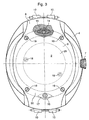
- the case 1 of a wristwatch is shown, the visible parts of which consist essentially of a cap 20 forming a middle part 4, in which a recess 5 is formed for the housing of the time-setting ring 7.
- the recess 5 comprises in its center a channel 26, visible on the figure 4 , which joins the inner surface of the cap 20 to allow the passage of the stem of the setting ring 7.
- the central portion of the cap 20 comprises, above a dial 11 provided with hour hands / minutes / seconds 13a, 13b, 13c, a sapphire crystal 3, whose fixing will be explained later.
- the cap 20 leaves, at the positions 12h-6h, below the middle part 4, an extension 8 of the bottom 2, curved outwards substantially according to the curvature of a wrist and provided with horns 10 serving fixing a bracelet (not shown). It is obvious that after fixing a bracelet this extension 8 will not be visible at all.
- the bottom 2 and the dial 11 delimit, with the casing ring 6, a housing 9 for a watch movement 29 held by two fixing screws 18 (also visible on the figure 3 ).
- the cap 20 has an oblong shape and covers, from the perimeter of the ice 3, the entire surface of the watch forming two lugs 28 extending above the extensions 8, being, like said extensions 8 curved towards the outside to form a dome.
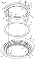
- the figure 4 is a representation in exploded perspective of the. assembly device, the different parts having the orientation in view from below represented at the figure 3 .
- the device comprises a metal center 30, an elastomer washer 12, two screws 14, 16 and two flanges 15, 17 which will allow the assembly of the cap 20.
- the inner wall of the cap has an annular stair structure formed from the base 21 by orthogonal flat surfaces 21a, 22, 22a, 23a.
- the base 21 is extended at the ears 28 by oblique extensions 24 having the same inclination as the extensions 8 of the bottom 2.
- the vertical portion 21a, joining the base 21 and parallel to the middle part 4 comprises at the ears 28 two recesses 25, 27 diametrically opposed and intended to receive the flanges 15, 17.
- these recesses are the only parts of the cap 20 which require special machining. They can for example be obtained by means of a diamond grinding, or by providing, during the manufacture of the cap of the drawers in the mold at the locations of the recesses 25, 27.
- the metal center 30 is formed of a ring whose outer surface has a stair shape, complementary to that of the cap 20, formed from the base 31, by flat surfaces 31a, 32, 32a, 33.
- the inner wall 46 of metal center 30 comprises at its base and at its upper part two annular grooves 45, 47 for receiving seals 45a, 47a respectively compressed axially against the bottom 2 and radially against the vertical edge 3a of the ice 3.
- bottom of the annular groove 47 is extended towards the inside of the casing 1 by a ring 40 which will form a flange between the spout 3b of the glass 3 and the dial 11. It is obvious that this ring 40 has only one optional character and that it could be replaced by an independent enhancement.
- the surface 33 of the metal center 30 comprises two open recesses 35, 37 which are diametrically opposed and intended to receive the flanges 15, 17.
- the recesses 35, 37 comprise in their substantially median part the axial bores 34, 36 in which will be engaged. the screws 14, 16 for fixing the flanges 15, 17.
- These clearances 35, 37 make it possible to reduce the height of the assembly device and facilitate the positioning of the center 30 above the flanges. According to a simpler embodiment, it is also possible to provide no clearance.
- the metal center 30 finally has, distributed around its periphery, four tapped holes 39 for fixing the bottom 2 by means of four screws 19, and a radial bore 38 for the passage of the crown rod 7.
- a first step from the central element formed by the metal center 30, it is possible to preassemble in a known manner all the constituent elements of the watch, ice 3, hands 13a, 13b, 13c, dial 11, circle d casing 6, movement 29 and crown 7, with the exception of the cap 20 and the bottom 2. It will also be observed, in the case where the ring 40 is replaced by an independent flange, that the metal center 30 and the circle of casing 6 can be made in one piece.
- the elastomer washer 12 is then placed on the annular surface 22 of the staircase structure of the cap 20, then the two flanges 15, 17 are engaged in the recesses 25, 27.
- the metal center 30 is then placed by positioning the clearance 35, 37 above the flanges 15, 17, and then screwed together by means of the screws 14, 16 so as to compress the washer 12 between the facing annular surfaces 22, 32 of the cap 20 and the metal center 30, and finally the bottom is screwed by means of the four screws 19.
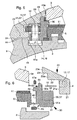
- the dimensions of the assembled elements and the thickness of the elastomer washer 12 are designed so that there are very small gaps between the internal surfaces of the cap 20 and the surfaces of the facing elements, with the exception of the surfaces 22, 32 between which is compressed the elastomeric washer 12.
- the clearance between the oblique extension 24 and the extension 8 of the bottom 2 is designated by the reference 44, that between the base 21 and the bottom 2 by the reference 41, that between the wall 21a and the corresponding wall 31a of the center 30 by the reference 41a, that between the wall 23 and the outer edge 33 of the center 20 by the reference 43, and that between the wall 23a and the edge 3a of the ice 3 by the reference 43a .
- the fixing means of the cap are two in number and are positioned under the bottom 2 positions 12h-6h, at the cap where there is the most material. Comparing the cuts of Figures 5 and 6 it will be observed that the point of the recesses 25, 27 closest to the surface of the cap 20 remains the same all around said cap, so that it is possible, according to an alternative embodiment, to consider putting more than two fixing means occupying different angular positions with respect to the axis 12h-6h. In the embodiment taken by way of example, it will be observed that the two axial bores 34, 36 and the four tapped holes 39 have an angular offset, that is to say that they are distinct and that only are apparent the screws 19 for fixing the bottom 2.
- the center 30 comprises only two tapped holes 39 for two screws 19 for fixing the bottom, the two other screws being merged with the screws 14, 16 of flange fixing 15, 17 having longer rods.
- this embodiment has the advantage of being able to replace the cap 20 without removing the bottom 2, and therefore without risk of damaging the seal 45a.
Landscapes
- Physics & Mathematics (AREA)
- General Physics & Mathematics (AREA)
- Engineering & Computer Science (AREA)
- Manufacturing & Machinery (AREA)
- Electric Clocks (AREA)
Description
- La présente invention a pour objet un dispositif d'assemblage d'une coiffe en matériau dur sur le bord supérieur de la carrure d'une boîte de montre.
- Dans une boîte de montre-bracelet les parties apparentes, c'est-à-dire la glace, la carrure et la coiffe sont les parties les plus exposées aux agressions extérieures, telles que les rayures, les chocs, l'oxydation, etc. Dans les produits de qualité, on élimine ou réduit les conséquences inesthétiques de ces agressions au niveau de la glace en utilisant un verre saphir dont la fabrication est certes délicate, mais dont la forme géométrique simple n'implique pas un usinage compliqué. Pour les autres parties extérieures, on a proposé depuis longtemps d'utiliser un matériau très dur, tel qu'une céramique. Un tel matériau a une résistance remarquable aux agressions extérieures, mais a comme inconvénients d'être encore sensible aux chocs et de très mal se prêter à des usinages trop complexes. Pour cette raison, ce matériau dur est le plus souvent utilisé comme habillage d'une structure sous-jacente plus facilement usinable et généralement bien meilleur marché.
- Pour rendre solidaire la structure et l'habillage, la solution la plus évidente est le collage, comme décrit par exemple dans le brevet
CH 517 963 CH 506 826 - Pour permettre le démontage et le remplacement d'une telle coiffe en matériau dur, le document
CH 508 925 - Pour remédier à l'inconvénient ci-dessus, le document
CH 568 040 - D'autres constructions se rattachent plus ou moins à celles évoquées ci-dessus, et en présentent les mêmes inconvénients.
- La présente invention a donc pour objet de remédier aux inconvénients de cet art antérieur en procurant un dispositif d'assemblage d'une coiffe en matériau dur sur le bord supérieur de la carrure d'une boîte de montre ou sur une pièce solidaire de celle-ci, ladite coiffe pouvant être obtenue avec un nombre réduit d'opérations d'usinage et pouvant être facilement remplacée en cas de bris.
- A cet effet l'invention a pour objet un dispositif d'assemblage amovible d'une coiffe en matériau dur sur le bord supérieur de la carrure d'une boîte de montre fermée par une glace et un fond délimitant avec un cercle d'emboîtage, un espace pour loger au moins un mouvement, caractérisé en ce qu'il comprend un centre métallique dont la paroi externe a une structure en escaliers complémentaire de la structure interne de la coiffe rendue solidaire dudit centre au moyen d'au moins deux vis le traversant à travers des perçages pour serrer des brides logées dans des creusures radiales formées dans une paroi verticale de la coiffe, en comprimant un joint élastomère disposé entre deux surfaces horizontales des structures en escalier, et dont l'épaisseur est suffisante pour ménager des jeux au moins entre des surfaces en regard respectivement du fond et de la base de la coiffe, et de la paroi verticale du centre et la paroi de la coiffe rejoignant la base.
- L'invention sera mieux comprise en prenant comme exemple illustratif et non limitatif un dispositif d'assemblage d'une coiffe en céramique sur une montre bracelet de forme oblongue, en référence aux dessins annexés dans lesquels
- la
figure 1 est une représentation en perspective; - la
figure 2 est une représentation en coupe selon la ligne brisée II-II de lafigure 1 passant par les positions horaires 3h et 6h; - la
figure 3 est une vue de dessous de la montre-bracelet représentée à lafigure 1 , le fond étant partiellement arraché au niveau d'une bride; - la
figure 4 est une représentation éclatée du dispositif d'assemblage; - la
figure 5 est une vue agrandie de la coupe II-II à la position 6h; - la
figure 6 est une représentation éclatée de la coupe selon la ligne VI-VI de lafigure 1 ; - En se référant aux
figures 1 et2 , on a représenté le boîtier 1 d'une montre-bracelet dont les parties visibles sont essentiellement constituées par une coiffe 20 formant une carrure 4, dans laquelle est formé un évidement 5 pour le logement de la couronne de mise à l'heure 7. L'évidement 5 comprend en son centre une gouttière 26, visible sur lafigure 4 , qui rejoint la surface intérieure de la coiffe 20 pour permettre le passage de la tige de la couronne de mise à l'heure 7. La partie centrale de la coiffe 20 comprend, au-dessus d'un cadran 11 pourvu d'aiguilles heures/minutes/secondes 13a, 13b, 13c, une glace saphir 3, dont la fixation sera expliquée plus loin. Comme on le voit, la coiffe 20 laisse apparent, aux positions 12h-6h, en dessous de la carrure 4, un prolongement 8 du fond 2, incurvé vers l'extérieur sensiblement selon la courbure d'un poignet et pourvu de cornes 10 servant à la fixation d'un bracelet (non représenté). Il est bien évident qu'après la fixation d'un bracelet ce prolongement 8 ne sera plus du tout visible. - Le fond 2 et le cadran 11 délimitent, avec le cercle d'emboîtage 6, un logement 9 pour un mouvement horloger 29 maintenu par deux vis de fixation 18 (visibles également sur la
figure 3 ). La coiffe 20 a une forme oblongue et recouvre, à partir du périmètre de la glace 3, toute la surface de la montre en formant deux oreilles 28 s'étendant au-dessus des prolongements 8, en étant, comme lesdits prolongements 8 incurvées vers l'extérieur pour former une coupole. - La
figure 4 est une représentation en perpective éclatée du. dispositif d'assemblage, les différentes pièces ayant l'orientation en vue de dessous représentées à lafigure 3 . On voit que le dispositif comprend un centre métallique 30, une rondelle élastomère 12, deux vis 14, 16 et deux brides 15, 17 qui vont permettre l'assemblage de la coiffe 20. - Comme représentée à plus grande échelle à la
figure 6 , la paroi intérieure de la coiffe présente une structure annulaire en escaliers constituée, depuis la base 21, par des surfaces planes orthogonales 21a, 22, 22a, 23a. - Comme on le voit à la
figure 5 , la base 21 est prolongée au niveau des oreilles 28 par des extensions obliques 24 ayant la même inclinaison que les prolongements 8 du fond 2. La partie verticale 21a, rejoignant la base 21 et parallèle à la carrure 4, comporte au niveau des oreilles 28 deux creusures 25, 27 diamétralement opposées et destinées à recevoir les brides 15, 17. Si on excepte les opérations de polissage des surfaces extérieures, ces creusures sont les seules parties de la coiffe 20 qui nécessitent un usinage particulier. Elles peuvent par exemple être obtenues au moyen d'un meulage diamanté, ou en prévoyant, lors de la fabrication de la coiffe des tiroirs dans le moule aux emplacements des creusures 25, 27. - Le centre métallique 30 est formé d'un anneau dont la surface extérieure a une forme en escaliers, complémentaire de celle de la coiffe 20, constituée, depuis la base 31, par des surfaces planes 31a, 32, 32a, 33. La paroi interne 46 de centre métallique 30 comprend à sa base et à sa partie supérieure deux rainures annulaires 45, 47 pour recevoir des joints d'étanchéité 45a, 47a comprimés respectivement axialement contre le fond 2 et radialement contre le bord vertical 3a de la glace 3. Le fond de la rainure annulaire 47 est prolongé vers l'intérieur du boîtier 1 par une bague 40 qui va former rehaut entre le bec 3b de la glace 3 et le cadran 11. Il est bien évident que cette bague 40 n'a qu'un caractère optionnel et qu'elle pourrait être remplacée par un rehaut indépendant.
- En se référant plus particulièrement aux
figures 4 et5 on voit que la surface 33 du centre métallique 30 comprend deux dégagements ouverts 35, 37 diamétralement opposés et destinés à recevoir les brides 15, 17. Les dégagements 35,37 comprennent dans leur partie sensiblement médiane les perçages axiaux 34, 36 dans lesquels seront engagées les vis 14, 16 de fixation des brides 15, 17. Ces dégagements 35, 37 permettent de réduire la hauteur du dispositif d'assemblage et facilitent le positionnement du centre 30 au-dessus des brides. Selon un mode de réalisation plus simple, il est également possible de ne prévoir aucun dégagement. Le centre métallique 30 comporte enfin, répartis sur son pourtour, quatre trous taraudés 39 pour la fixation du fond 2 au moyen de quatre vis 19, ainsi qu'un perçage radial 38 pour le passage de la tige de la couronne 7. - Comme on le voit, toutes les opérations d'usinage, qui seraient difficiles, voire impossibles à réaliser sur un matériau extra dur sont facilement réalisables sur un anneau de section initiale rectangulaire par exemple en acier ou en laiton.
- En se référant maintenant plus particulièrement aux
figures 4 à 6 on indique ci-après comment le dispositif selon l'invention rend très faciles les opérations de montage ou démontage de la coiffe 20. - Dans une première étape, à partir de l'élément central formé par le centre métallique 30, il est possible de préassembler de façon connue tous les éléments constitutifs de la montre, glace 3 , aiguilles 13a, 13b, 13c, cadran 11, cercle d'emboîtage 6 , mouvement 29 et couronne 7 , à l'exception de la coiffe 20 et du fond 2. On observera également, dans le cas où la bague 40 est remplacée par un rehaut indépendant, que le centre métallique 30 et le cercle d'emboîtage 6 peuvent être réalisés en une seule pièce.
- On met ensuite en place la rondelle élastomère 12 sur la surface annulaire 22 de la structure en escaliers de la coiffe 20, puis on engage les deux brides 15, 17 dans les creusures 25, 27. On pose ensuite le centre métallique 30 en positionnant les dégagements 35, 37 au-dessus des brides 15, 17, puis on visse l'ensemble au moyen des vis 14, 16 de façon à comprimer la rondelle 12 entre les surfaces annulaires en regard 22, 32 de la coiffe 20 et du centre métallique 30, et finalement on visse le fond au moyen des quatre vis 19.
- Comme on le voit sur la
figure 5 , les cotes des éléments assemblés et l'épaisseur de la rondelle élastomère 12 sont prévues pour qu'il existe de très faibles jeux entre les surfaces internes de la coiffe 20 et les surfaces des éléments en regard, à l'exception des surfaces 22, 32 entre lesquelles est comprimée la rondelle élastomère 12. Le jeu entre l'extension oblique 24 et le prolongement 8 du fond 2 est désigné par la référence 44, celui entre la base 21 et le fond 2 par la référence 41, celui entre la paroi 21a et la paroi correspondante 31a du centre 30 par la référence 41a, celui entre la paroi 23 et le bord externe 33 du centre 20 par la référence 43, et celui entre la paroi 23a et le bord 3a de la glace 3 par la référence 43a. Le jeu entre la paroi 22a et la surface correspondante 32a du centre est pratiquement inexistant de sorte qu'il est plus exact de dire qu'à cet endroit on a un ajustage gras. Ces jeux ont volontairement été prévus pour permettre un faible basculement de la coiffe 20 en cas de choc léger et éviter ainsi de la briser. Si le choc est trop important, et provoque un dommage irréversible de la coiffe 20, il sera très facile de la remplacer en déposant le fond 2 et en dévissant les deux vis 14, 16. - Dans l'exemple représenté, les moyens de fixation de la coiffe sont au nombre de deux et sont positionnés sous le fond 2 aux positions 12h-6h, au niveau de la coiffe où il existe le plus de matière. En comparant les coupes des
figures 5 et 6 on observera que le point des creusures 25, 27 les plus rapproché de la surface de la coiffe 20 reste le même sur tout le pourtour de ladite coiffe, de sorte qu'on peut, selon une variante d'exécution, envisager de mettre plus de deux moyens de fixation occupant des positions angulaires différentes par rapport à l'axe 12h-6h. Dans le mode de réalisation pris à titre d'exemple, on observera que les deux perçages axiaux 34, 36 et les quatre trous taraudés 39 présentent un décalage angulaire, c'est-à-dire qu'ils sont distincts et que seules sont apparentes les vis 19 de fixation du fond 2. Selon une variante d'exécution non représentée, le centre 30 ne comprend que deux trous taraudés 39 pour deux vis 19 de fixation du fond, les deux autres vis étant confondues avec les vis 14, 16 de fixation de bride 15, 17 en ayant des tiges plus longues. Par rapport au processus de montage/démontage décrit précédemment, ce mode de réalisation présente l'avantage de pouvoir remplacer la coiffe 20 sans déposer le fond 2, et donc sans risque d'endommager le joint d'étanchéité 45a. - L'exemple qui vient d'être décrit concerne un cadran de forme circulaire avec une coiffe oblongue, mais il est bien évident que l'homme de métier peut, sans sortir du cadre de la présente invention, adapter ce dispositif de fixation à tout type de coiffe et à tout type de cadran.
Claims (8)
- Dispositif d'assemblage amovible d'une coiffe (20) en matériau dur sur la partie supérieure de la carrure (4) d'une boîte de montre (1) fermée par une glace (3) et un fond (2) délimitant avec un cercle d'emboîtage (6), un espace (9) pour loger au moins un mouvement (29), caractérisé en ce qu'il comprend un centre métallique (30) dont la paroi externe a une structure en escaliers (31, 31a, 32, 32a, 33) complémentaire de la structure interne (21, 21a, 22, 22a, 23, 23a) de la coiffe (20) rendue solidaire dudit centre (30) au moyen d'au moins deux vis (14, 16) le traversant à travers des perçages (34, 36) pour serrer des brides (15, 17) logées dans des creusures radiales (25, 27) formées dans une paroi (21 a) verticale de la coiffe (20) en comprimant un joint élastomère (12), disposé entre deux surfaces horizontales (22, 32) des structures en escaliers, et dont l'épaisseur est suffisante pour ménager des jeux (41, 41a) au moins entre des surfaces en regard respectivement du fond (2) et de la base (21) de la coiffe (20), et de la paroi verticale (31 a) du centre (30) et la paroi (21 a) de la coiffe (20) rejoignant la base (21).
- Dispositif selon la revendication 1, caractérisé en ce que le centre (30) comprend en outre des dégagements (35, 37) ouverts vers la coiffe (20) aux emplacements des brides (15, 17) et ayant sensiblement pour profondeur l'épaisseur desdites brides (15, 17).
- Dispositif selon la revendication 1, caractérisé en ce que le centre (30) comprend en outre des trous taraudés (39) décalés angulairement par rapport aux perçages pour les vis (14, 16) de bride (15, 17) et permettant la fixation du fond (2) au moyen de vis (19).
- Dispositif selon la revendication 3, caractérisé en ce que deux vis (14, 16) de fixation de bride (15, 17) permettent aussi la fixation du fond (2).
- Dispositif selon la revendication 1, caractérisé en ce que la coiffe (20) a une forme oblongue et comporte deux creusures (25, 27) positionnées à 12h et 6h.
- Dispositif selon la revendication 1, caractérisé en ce que les bords internes du centre (20) comportent en outre deux rainures (45, 47) destinées à recevoir deux joints (45a, 47a) permettant d'assurer l'étanchéité avec le fond (2) et avec la glace (3).
- Dispositif selon la revendication 1, caractérisé en ce que la partie supérieure de la paroi interne du centre (30) comprend une extension annulaire (40) formant rehaut.
- Dispositif selon la revendication 1, caractérisé en ce que le centre (30) et le cercle d'emboîtage (6) sont confondus en une seule pièce.
Priority Applications (2)
| Application Number | Priority Date | Filing Date | Title |
|---|---|---|---|
| DE69940381T DE69940381D1 (de) | 1999-11-17 | 1999-11-17 | Vorrichtung zum Aufsetzen einer Schutzkappe aus hartem Material auf den Mittelteil einer Uhr |
| EP99122881A EP1102136B1 (fr) | 1999-11-17 | 1999-11-17 | Dispositif d'assemblage d'une coiffe en matériau dur sur la carrure d'une montre |
Applications Claiming Priority (1)
| Application Number | Priority Date | Filing Date | Title |
|---|---|---|---|
| EP99122881A EP1102136B1 (fr) | 1999-11-17 | 1999-11-17 | Dispositif d'assemblage d'une coiffe en matériau dur sur la carrure d'une montre |
Publications (2)
| Publication Number | Publication Date |
|---|---|
| EP1102136A1 EP1102136A1 (fr) | 2001-05-23 |
| EP1102136B1 true EP1102136B1 (fr) | 2009-02-04 |
Family
ID=8239417
Family Applications (1)
| Application Number | Title | Priority Date | Filing Date |
|---|---|---|---|
| EP99122881A Expired - Lifetime EP1102136B1 (fr) | 1999-11-17 | 1999-11-17 | Dispositif d'assemblage d'une coiffe en matériau dur sur la carrure d'une montre |
Country Status (2)
| Country | Link |
|---|---|
| EP (1) | EP1102136B1 (fr) |
| DE (1) | DE69940381D1 (fr) |
Families Citing this family (6)
| Publication number | Priority date | Publication date | Assignee | Title |
|---|---|---|---|---|
| EP2107432B1 (fr) | 2008-04-01 | 2011-06-29 | Montres Rado S.A. | Dispositif de commande à poussoir pour montre |
| CN103343765B (zh) * | 2013-05-21 | 2015-11-11 | 张宝喜 | 用于手表、怀表和首饰的分体式金属实体连接装置 |
| CN104317181A (zh) * | 2014-08-26 | 2015-01-28 | 上海稻房投资有限公司 | 一种陶瓷背板防水手表 |
| CN107193200A (zh) * | 2017-07-19 | 2017-09-22 | 深圳市雷诺表业有限公司 | 一种可旋转快速拆卸的手表组合结构及手表 |
| CN109375490A (zh) * | 2018-11-16 | 2019-02-22 | 深圳市稳达时钟表有限公司 | 一种组合式diy手表及组合式diy手表的组装方法 |
| CN110824883B (zh) * | 2019-12-18 | 2024-07-09 | 东莞市天铭钟表有限公司 | 一种多层结构陀飞轮机械表 |
Family Cites Families (9)
| Publication number | Priority date | Publication date | Assignee | Title |
|---|---|---|---|---|
| CH311861A (fr) * | 1953-09-28 | 1955-12-15 | Derobert Jean | Montre. |
| CH517963A (fr) | 1960-10-05 | 1972-02-29 | Schlup & Cie S A | Boîte de montre |
| CH508925A (fr) | 1968-09-27 | 1971-02-15 | Piquerez Sa Ervin | Montre-bracelet comportant un écran protecteur |
| CH1766468A4 (fr) | 1968-11-25 | 1970-10-30 | ||
| US3643423A (en) * | 1969-09-30 | 1972-02-22 | Piquerez Sa Ervin | Protective screen for a timepiece casing |
| FR2231042A1 (en) * | 1973-05-23 | 1974-12-20 | Chatenoud Gilles | Wrist watch with interchangeable decorative surround - covers point where bracelet is secured to watch case |
| CH568040A5 (en) | 1973-09-14 | 1975-12-15 | Weill Ernst | Tooth brush with rotatable head - enables vertical cleaning movements to be made more easily and efficiently |
| CH667966GA3 (en) * | 1987-02-18 | 1988-11-30 | Sealed wrist watch casing - has plastic body and precious metal surround with e.g. gold restricted to part of watch thickness | |
| CH684297B5 (fr) * | 1993-04-20 | 1995-02-28 | Blancpain Sa | Boîte de montre présentant une lunette amovible. |
-
1999
- 1999-11-17 EP EP99122881A patent/EP1102136B1/fr not_active Expired - Lifetime
- 1999-11-17 DE DE69940381T patent/DE69940381D1/de not_active Expired - Lifetime
Also Published As
| Publication number | Publication date |
|---|---|
| DE69940381D1 (de) | 2009-03-19 |
| EP1102136A1 (fr) | 2001-05-23 |
Similar Documents
| Publication | Publication Date | Title |
|---|---|---|
| EP2859412B1 (fr) | Systeme de lunette tournante | |
| EP3540523B1 (fr) | Montre comprenant une boite de montre munie de deux cadrans | |
| EP3736642B1 (fr) | Boite de montre etanche | |
| CH678254B5 (fr) | ||
| EP4145230B1 (fr) | Lunette pour piece d'horlogerie | |
| EP1680715B1 (fr) | Piece d'horlogerie a boite de montre reversible | |
| EP1102136B1 (fr) | Dispositif d'assemblage d'une coiffe en matériau dur sur la carrure d'une montre | |
| EP1065576B1 (fr) | Montre chronographe en métal noble à carrure-lunette évidée | |
| EP0327829A1 (fr) | Boîte de montre étanche | |
| CH690870A5 (fr) | Boîte de montre étanche. | |
| EP0168010A1 (fr) | Boîte de montre | |
| EP0370356B1 (fr) | Boîte de montre comportant une carrure frittée | |
| EP1975747A2 (fr) | Boîte de montre | |
| EP3896535A1 (fr) | Systeme d'etancheite pour boite de piece d'horlogerie | |
| EP0770937B1 (fr) | Pièce d'horlogerie comportant une lunette tournante | |
| EP1241541B1 (fr) | Boîte de montre assemblée par la lunette | |
| EP3321749B1 (fr) | Joint d'étanchéité pour l'horlogerie | |
| EP4250020B1 (fr) | Boîte de montre à lunette tournante | |
| EP4198646B1 (fr) | Boite de montre etanche a joint de fixation | |
| EP3756904B1 (fr) | Instrument d'ecriture comprenant une capsule agencee pour recevoir un mouvement horloger | |
| EP1291739B1 (fr) | Boîte de montre étanche et son procédé de montage | |
| EP3736641A1 (fr) | Tige-couronne d'une boîte de montre étanche, et boîte de montre la comprenant | |
| CH712378B1 (fr) | Boîte de montre à aspect visuel asymétrique | |
| CH714749B1 (fr) | Montre comprenant une boîte de montre munie de deux cadrans. | |
| CH709079B1 (fr) | Boîte de montre comprenant des moyens de fixation de la glace à la carrure. |
Legal Events
| Date | Code | Title | Description |
|---|---|---|---|
| PUAI | Public reference made under article 153(3) epc to a published international application that has entered the european phase |
Free format text: ORIGINAL CODE: 0009012 |
|
| AK | Designated contracting states |
Kind code of ref document: A1 Designated state(s): CH DE FR GB IT LI |
|
| AX | Request for extension of the european patent |
Free format text: AL;LT;LV;MK;RO;SI |
|
| 17P | Request for examination filed |
Effective date: 20011123 |
|
| AKX | Designation fees paid |
Free format text: CH DE FR GB IT LI |
|
| 17Q | First examination report despatched |
Effective date: 20071008 |
|
| GRAP | Despatch of communication of intention to grant a patent |
Free format text: ORIGINAL CODE: EPIDOSNIGR1 |
|
| GRAS | Grant fee paid |
Free format text: ORIGINAL CODE: EPIDOSNIGR3 |
|
| GRAS | Grant fee paid |
Free format text: ORIGINAL CODE: EPIDOSNIGR3 |
|
| GRAA | (expected) grant |
Free format text: ORIGINAL CODE: 0009210 |
|
| AK | Designated contracting states |
Kind code of ref document: B1 Designated state(s): CH DE FR GB IT LI |
|
| REG | Reference to a national code |
Ref country code: GB Ref legal event code: FG4D Free format text: NOT ENGLISH |
|
| REG | Reference to a national code |
Ref country code: CH Ref legal event code: EP |
|
| REG | Reference to a national code |
Ref country code: CH Ref legal event code: NV Representative=s name: ICB INGENIEURS CONSEILS EN BREVETS SA |
|
| REF | Corresponds to: |
Ref document number: 69940381 Country of ref document: DE Date of ref document: 20090319 Kind code of ref document: P |
|
| PLBE | No opposition filed within time limit |
Free format text: ORIGINAL CODE: 0009261 |
|
| STAA | Information on the status of an ep patent application or granted ep patent |
Free format text: STATUS: NO OPPOSITION FILED WITHIN TIME LIMIT |
|
| 26N | No opposition filed |
Effective date: 20091105 |
|
| REG | Reference to a national code |
Ref country code: FR Ref legal event code: PLFP Year of fee payment: 17 |
|
| REG | Reference to a national code |
Ref country code: FR Ref legal event code: PLFP Year of fee payment: 18 |
|
| PGFP | Annual fee paid to national office [announced via postgrant information from national office to epo] |
Ref country code: FR Payment date: 20161024 Year of fee payment: 18 Ref country code: DE Payment date: 20161020 Year of fee payment: 18 |
|
| PGFP | Annual fee paid to national office [announced via postgrant information from national office to epo] |
Ref country code: IT Payment date: 20161025 Year of fee payment: 18 |
|
| REG | Reference to a national code |
Ref country code: DE Ref legal event code: R119 Ref document number: 69940381 Country of ref document: DE |
|
| REG | Reference to a national code |
Ref country code: FR Ref legal event code: ST Effective date: 20180731 |
|
| PG25 | Lapsed in a contracting state [announced via postgrant information from national office to epo] |
Ref country code: IT Free format text: LAPSE BECAUSE OF NON-PAYMENT OF DUE FEES Effective date: 20171117 Ref country code: DE Free format text: LAPSE BECAUSE OF NON-PAYMENT OF DUE FEES Effective date: 20180602 Ref country code: FR Free format text: LAPSE BECAUSE OF NON-PAYMENT OF DUE FEES Effective date: 20171130 |
|
| PGFP | Annual fee paid to national office [announced via postgrant information from national office to epo] |
Ref country code: CH Payment date: 20181030 Year of fee payment: 20 Ref country code: GB Payment date: 20181024 Year of fee payment: 20 |
|
| REG | Reference to a national code |
Ref country code: CH Ref legal event code: PL |
|
| REG | Reference to a national code |
Ref country code: GB Ref legal event code: PE20 Expiry date: 20191116 |
|
| PG25 | Lapsed in a contracting state [announced via postgrant information from national office to epo] |
Ref country code: GB Free format text: LAPSE BECAUSE OF EXPIRATION OF PROTECTION Effective date: 20191116 |