EP1102128A2 - Gleitstützmechanismus für ein dielektrisches Trägerelement in einem elektrostatographischen Vervielfältigungsapparat - Google Patents
Gleitstützmechanismus für ein dielektrisches Trägerelement in einem elektrostatographischen Vervielfältigungsapparat Download PDFInfo
- Publication number
- EP1102128A2 EP1102128A2 EP00124992A EP00124992A EP1102128A2 EP 1102128 A2 EP1102128 A2 EP 1102128A2 EP 00124992 A EP00124992 A EP 00124992A EP 00124992 A EP00124992 A EP 00124992A EP 1102128 A2 EP1102128 A2 EP 1102128A2
- Authority
- EP
- European Patent Office
- Prior art keywords
- frame
- roller
- shaped component
- reproduction apparatus
- dielectric
- Prior art date
- Legal status (The legal status is an assumption and is not a legal conclusion. Google has not performed a legal analysis and makes no representation as to the accuracy of the status listed.)
- Withdrawn
Links
- 239000002245 particle Substances 0.000 description 11
- 230000009977 dual effect Effects 0.000 description 8
- 230000033458 reproduction Effects 0.000 description 7
- 239000000463 material Substances 0.000 description 4
- 239000000126 substance Substances 0.000 description 4
- 238000000034 method Methods 0.000 description 3
- 238000004519 manufacturing process Methods 0.000 description 2
- 230000015556 catabolic process Effects 0.000 description 1
- 238000006731 degradation reaction Methods 0.000 description 1
- 238000006073 displacement reaction Methods 0.000 description 1
- 230000000694 effects Effects 0.000 description 1
- 230000005684 electric field Effects 0.000 description 1
- 239000004744 fabric Substances 0.000 description 1
- 238000010438 heat treatment Methods 0.000 description 1
- 238000012423 maintenance Methods 0.000 description 1
- 239000000049 pigment Substances 0.000 description 1
Images


Classifications
-
- G—PHYSICS
- G03—PHOTOGRAPHY; CINEMATOGRAPHY; ANALOGOUS TECHNIQUES USING WAVES OTHER THAN OPTICAL WAVES; ELECTROGRAPHY; HOLOGRAPHY
- G03G—ELECTROGRAPHY; ELECTROPHOTOGRAPHY; MAGNETOGRAPHY
- G03G15/00—Apparatus for electrographic processes using a charge pattern
- G03G15/75—Details relating to xerographic drum, band or plate, e.g. replacing, testing
- G03G15/754—Details relating to xerographic drum, band or plate, e.g. replacing, testing relating to band, e.g. tensioning
Definitions
- the present invention relates to the positioning of a dielectric carrier element for electrographic duplicators in operative connection with a roller-shaped component of the reproduction apparatus.
- this roller-shaped Component of the duplicating apparatus can, for example, be a Act toner roller within the developer unit of a duplicator.
- the magnetic brush development unit includes one Housing that has a plurality of elements and a container with a supply of developer substance.
- the developer substance can e.g. be a two-component substance that magnetic carrier particles and, in comparison, smaller pigment particles Includes marking particles.
- the developer unit also includes one Mixer arrangement, e.g. a screw mixer or a belt mixer, which is in the Container is located and serves to the carrier particles and the marking particles move to electrically charge the particles so that the marking particles adhere to the surface of the carrier particles.
- a transport device does that Developer material from the container into a box, which is characterized by a variety of Magnets are generated, which are arranged on a rotating sleeve, which is usually is called a toner roller (of course, the magnets could also rotate and the Sleeve be stationary or at a different angular velocity than the magnets rotate).
- the rotating sleeve and the magnetic fields cause the Marking particles in the vicinity of the latent image charge pattern on the dielectric Carrier element brought and applied to the latent image charge pattern, so the patterns can be developed.
- the distance between the dielectric carrier element and the Toner roller in the developer unit very important for the production of qualitative high quality reproductions and to maintain an efficient way of working of the duplicating apparatus.
- the distance of the dielectric support element to that Toner roller forms a small gap, through which developer material with a desired Flow rate must occur. If the gap is too small for a certain developer flow rate is a bottleneck that prevents the developer material efficiently through the gap flows. In this case, the developer does not develop the latent image charge pattern reasonable, so that unacceptable reproductions of the information to be reproduced getting produced. In addition, the developer substance can become undesirable Directions in the duplicator, moving the inside of the Damage the duplicator.
- a bottleneck in the gap can thereby be avoided that both the flow rate of the fabric and the distance of the toner roller to the dielectric support element are strictly controlled.
- the tolerance value regarding the Distance can become less important if one of the components is made that it compensates for larger flow rates by increasing the distance.
- the gap can be controlled efficiently by using an optional one movable support device for a dielectric support element is provided.
- the optionally movable support device for the dielectric support element can be in Form of a simple sliding arrangement with a sliding element or a dual Sliding arrangement can be designed with two sliding elements, but also a larger number of Sliding elements are conceivable.
- a dielectric Carrier element is a sliding element on one side instead of directly over one roller-shaped component of the reproduction apparatus.
- the dielectric is then directly above the roller-shaped component, where the narrowest section of the gap is located, slightly movable.
- the dielectric Carrier element can give way so that the developer flow through the gap is not too much restrict.
- the dual sliding arrangement is preferable to the simple sliding arrangement, since it is the dielectric support element on both sides of the roller-shaped component supports.
- the invention is therefore based on the object of a support device for accurate Positioning a dielectric support for electrographic duplicators in operative connection with a roller-shaped component of the reproduction apparatus to accomplish.
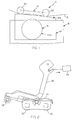
- FIG. 1 shows a schematic view of a dielectric support device Carrier element, wherein the support device is designated by the reference numeral 10.
- the Support device 10 according to the invention comprises a sliding arrangement 12 for supporting a Portion of a movable dielectric support member 14 to the portion of the dielectric support member relative to the toner roller 16a Duplicator developing unit 18 during the Position the duplication process exactly.
- the sliding assembly 12, the clearest from the FIG. 2 and 3, comprises a plurality of sliding elements, preferably two sliding elements 20 and 22, which are designed so that they dielectric carrier element 14 for the precise, desired displacement of a defined free-stretched section of the dielectric carrier element in operative connection with the Conduct the toner roller 16a, but with the web guide of the dielectric carrier element act only minimal countermovement. While the two sliding elements 20 and 22 as elongated rods are formed, other embodiments such as e.g. Slide strips are also suitable for use in accordance with the invention.
- the two sliding elements 20 and 22 of the sliding arrangement 12 are in a frame 24 appropriate.
- the frame 24 includes a pair of end pieces 26a, 26b that meet the ends of the support respective sliding elements 20 and 22. Therefore, the frame 24 is used for positioning the sliding elements 20 and 22 in relation to each other and to maintain a certain predetermined distance between the sliding elements 20 and 22.
- the frame 24 is attached to a swivel bar 28 which is in a position in operative relationship with the Developer unit 18 is arranged in the duplicator.
- a pair of support arms 30, 32 and a load arm 36 serve to fasten the frame 24 to the swivel bar 28
- the support arms 30, 32 are each at one end on the pivot bar 28 near the End pieces attached (see FIG. 3).
- the opposite ends of the respective support arms 30, 32 grip a pivot rod 34 which in the end pieces 26a, 26b of the frame 24th and is held in the elongated holes 30a, 32a, which are located in the support arms. How best from FIG. 4, the support arms 30, 32 allow the Hold the pivot rod 34, the rotation of the pivot rod in the ends of the support arms, while supporting them at the same time.
- the load arm 36 is also at one end of the Swivel bar 28, attached approximately at its center. The opposite end of the Load arm 36 engages pivot rod 34, as shown in FIG.
- FIG. 3 and 5 best shows with a U-shaped slot 36a in a way that a force caused by the Torque is caused on the pivot bar 28 (in the manner shown below) is transmitted to the load arm 36 and thus to the swivel rod 34.
- Farther enables the special connection of the load arm 36 with the pivot rod 34 that Rotate the swivel rod about an axis perpendicular to the longitudinal axis of the Swivel rod.
- a rocker arm 38 is connected at one end to the swivel bar 28.
- force-applying device 40 e.g. a solenoid
- the Rocker arm 38 is in operative connection with the Rocker arm 38 to selectively transmit torque to the pivot bar 28 which in turn, the swivel rod 34 is loaded with a load by means of the load arm 36.
- the Swivel rod 34 thus applies a force to the frame 24, which in turn acts on the Sliding elements 20, 22 is passed on.
- the sliding elements 20, 22 are thus with the Cam track surface members 42a held in contact with the end fasteners 42 for the toner roller 16a (see FIG. 1, the one Cam surface element shows).
- the two roller end attachments 42 (one in front and one arranged in the rear of the magnetic brush development unit 18) support the Toner roller 16a and create precise locking positions for the sliding elements 20, 22 of the Support device 10.
- the toner roller 16a is arranged between the two end fastenings 42.
- the free-stretched portion of the dielectric support element 14 is in a plane that of the two sliding elements 20, 22 of the sliding arrangement 12 of the support device 10 are generated is kept in operative connection with the toner roller 16a.
- the developer unit 18 can build up tolerance in relation to the sliding arrangement 12 of the support device 10 can be positioned slightly shifted to the right or left (see FIG. 1).
- To the impact of the deviation of the positions to the left or right of the To minimize developer unit in relation to the support device are the Cam track surfaces 42a of end mounts 42 to a predetermined degree beveled.
- the slope of the cam surface is chosen such that while the developer unit 18 in relation to the sliding arrangement 12 of the support device 10 moves left or right, the area of the section of the dielectric Carrier element 14, between the two sliding elements 20, 22 of the support device is formed at a substantially fixed distance from the longitudinal axis of the The toner roller can rotate around the toner roller 16a.
- the arrangement of the Cam track surface 42a of roller end fittings 42 is a function of Geometry of the sliding elements and the toner roller diameter.
- the dielectric support member 14 remains with each relative left-right movement the developer unit 18 of the support device 10 at the same desired distance from the toner roller 16a for optimal development of a latent image charge pattern; i.e., while the roller end mounts 42 (and the toner roller) with respect to the Support device 10 are moved to the left or right, contact the sliding elements 20, 22, the respective cam track surfaces 42a of the end bracket 42 at different Positions. So the frame 24 of the support device 10 rotates about the pivot rod 34, while the sliding elements have different points on the beveled arrangement of the Contact cam track surface 42a of roller end mount 42. The area of the dielectric carrier element 14 rotates with the sliding elements 20, 22 and receives the desired optimal gap between the portion of the dielectric support member 14 and the toner roller 16a.
- the dual Slide support device 10 has four contact points with cam track surfaces 42a (i.e. two contact points per sliding element). Hence it could lead to such overdetermination come.
- the slide support device is by two Axles can be swiveled and in addition the frame of the device can move around its own Twist the longitudinal axis.
- the frame 24 can thus about the longitudinal axis of the Rotate pivot rod 34 and in addition about an axis perpendicular to the longitudinal axis of the Swivel bar to the point where the load arm 36 contacts the swivel bar.
- the frame 24 is as rigid as possible so that the Frame can rotate about its own longitudinal axis.
- the frame 24 of the support device 10 can all four points of the sliding elements 20, 22 of the support device Contact the developer unit end fasteners 42.
- the dielectric support element 14 bridges the gap with the toner roller 16a, taking the effects of Positioning the two sliding elements in the middle compensates and the desired Distance between the dielectric support member and the toner roller receives.
- the Twisting action on the frame 24 is minimized because the tolerance of the parts of the Support device 10 is controlled so that excessive distortion of the dielectric Carrier element and possible quality degradation of the image can be avoided.
Landscapes
- Physics & Mathematics (AREA)
- General Physics & Mathematics (AREA)
- Dry Development In Electrophotography (AREA)
- Specific Conveyance Elements (AREA)
- Registering, Tensioning, Guiding Webs, And Rollers Therefor (AREA)
Abstract
Description
- Figur 1
- eine schematische Seitenansicht mit Auslassungen zur Verdeutlichung eines dielektrischen Trägerelements eines elektrostatographischen Vervielfältigungsapparats, das anhand einer erfindungsgemäßen dualen Gleitstützvorrichtung in genaue Wirkposition mit der Entwicklereinheit des Vervielfältigungsapparats gebracht ist;
- Figur 2
- eine Seitenansicht mit Auslassungen zur Verdeutlichung einer erfindungsgemäßen dualen Gleitstützvorrichtung nach FIG. 1;
- Figur 3
- eine perspektivische Ansicht einer erfindungsgemäßen dualen Gleitstützvorrichtung nach FIG. 1;
- Figur 4
- eine vergrößerte Seitenansicht im Querschnitt eines Abschnitts der dualen Gleitstützvorrichtung nach FIG. 2, in der die Verbindung der Stützarme mit dem Rahmen der Stützvorrichtung dargestellt ist; und
- Figur 5
- eine vergrößerte Seitenansicht im Querschnitt eines Abschnitts der dualen Gleitstützvorrichtung nach FIG. 2, die die Verbindung eines Lastarms mit dem Rahmen der Stützvorrichtung darstellt.
- 10
- Stützvorrichtung
- 12
- Gleitanordnung
- 14
- Trägerelement
- 16
- Walzenförmige Komponente
- 16a
- Tonerwalze
- 18
- Entwicklereinheit
- 20
- Gleitelement
- 22
- Gleitelement
- 24
- Rahmen
- 26a
- Endstück
- 26b
- Endstück
- 28
- Schwenkleiste
- 30
- Stützarm
- 30a
- Langloch
- 32
- Stützarm
- 32a
- Langloch
- 34
- Schwenkstange
- 36
- Lastarm
- 36a
- U-förmiger Schlitz
- 38
- Kipphebel
- 40
- kraftausübende Vorrichtung
- 42
- Endbefestigungen
- 42a
- Nockbahnoberflächenelemente
Claims (12)
- Stützvorrichtung zur genauen Positionierung eines dielektrischen Trägerelements (14) für einen elektrostatographischen Vervielfältigungsapparat in Wirkverbindung mit einer walzenförmigen Komponente eines Vervielfältigungsapparats
dadurch gekennzeichnet,dass diese Stützvorrichtungeine Gleitanordnung (12), die einen langgestreckten Rahmen (24) und eine Vielzahl von Gleitelementen (20, 22) umfasst, die in dem Rahmen (24) befestigt sind, undeine Ebene für einen Abschnitt des dielektrischen Trägerelements (14) aufspannen;Endbefestigungen (42), die mit der walzenförmigen Komponente des Vervielfältigungsapparats verbunden sind, wobei die Endbefestigungen (42) und die jeweiligen Nockenbahnoberflächen (42a) einen vorgegebenen Abstand von der Längsachse der walzenförmigen Komponente eines Vervielfältigungsapparats definieren;und einen Lastarm (36), der den Rahmen (24) der Gleitanordnung (12) in eine Richtung drückt, damit die Gleitelemente (20, 22) in Verbindung mit den Nockenbahnoberflächen (42a) der Endbefestigungen (42) bleiben und die Ebene des Abschnitts des dielektrischen Trägerelements (14) im Wesentlichen in einem bestimmten Abstand von der walzenförmigen Komponente (16) erhalten bleibt, umfasst. - Vorrichtung nach Anspruch 1,
dadurch gekennzeichnet,
dass Gleitelemente (20, 22) im Rahmen (24) der Gleitanordnung (12) so befestigt sind, dass sie einen festen, vorgegebenen Abstand einhalten. - Vorrichtung nach einem der Ansprüche 1 bis 2,
dadurch gekennzeichnet,
dass es sich um genau zwei Gleitelemente (20, 22) handelt, die im Rahmen (24) der Gleitanordnung (12) befestigt sind. - Vorrichtung nach einem der Ansprüche 1 bis 3,
dadurch gekennzeichnet,
dass sich die walzenförmige Komponente (16) eines Vervielfältigungsapparats innerhalb der Entwicklereinheit (18) dieses Vervielfältigungsapparats befindet. - Vorrichtung nach einem der Ansprüche 1 bis 4,
dadurch gekennzeichnet,
dass es sich bei der walzenförmigen Komponente (16) eines Vervielfältigungsapparats um die Tonerwalze (16a) einer Magnetbürstenentwicklereinheit (18) dieses Vervielfältigungsapparats handelt. - Vorrichtung nach einem der Ansprüche 1 bis 5,
dadurch gekennzeichnet,
dass die Gleitanordnung (12) des weiteren eine Schwenkstange (34) umfasst, die eine Längsachse für den Rahmen (24) der Gleitanordnung (12) umfasst, um die der Rahmen (24) schwenkbar ist, und innerhalb der der Lastarm (36) auf die Schwenkstange (34) einwirken kann. - Vorrichtung nach einem der Ansprüche 1 bis 6,
dadurch gekennzeichnet,
dass der Lastarm (36) mit der Schwenkstange (34) in Verbindung steht, so dass der Rahmen (24) um eine Achse senkrecht zu der Längsachse der Schwenkstange (34) schwenkbar ist. - Vorrichtung nach einem der Ansprüche 1 bis 7
dadurch gekennzeichnet,
dass eine Schwenkleiste (28), die in einem Abstand zu dem Rahmen (24) angeordnet ist, wobei der Lastarm (36), der auf die Schwenkstange (34) einwirkt, mit der Schwenkleiste (28) in Verbindung steht. - Vorrichtung nach einem der Ansprüche 1 bis 8
dadurch gekennzeichnet,
dass mindestens ein Stützarm (30, 32), der mit der Schwenkstange (34) des Rahmens (24) der Gleitanordnung (12) in Verbindung steht, diese stützt. - Vorrichtung nach einem der Ansprüche 1 bis 9
dadurch gekennzeichnet,
dass eine kraftausübende Vorrichtung (40) mit dem Kipphebel (38) verbunden ist, der mit der Schwenkleiste (28) verbunden ist, und den Kipphebel (38) gezielt bewegen kann, so dass der Lastarm (36) eine Kraft auf den Rahmen (24) ausüben kann. - Vorrichtung nach Anspruch 10
dadurch gekennzeichnet,
dass es sich bei der kraftausübenden Vorrichtung (40) um eine Magnetspule handelt. - Vorrichtung nach einem der Ansprüche 1 bis 11
dadurch gekennzeichnet,
dass der Rahmen (24) der Gleitanordnung (12) in seiner Struktur flexibel ist, so dass der Rahmen (24) um seine Längsachse drehbar ist.
Applications Claiming Priority (2)
| Application Number | Priority Date | Filing Date | Title |
|---|---|---|---|
| US44375499A | 1999-11-19 | 1999-11-19 | |
| US443754 | 1999-11-19 |
Publications (2)
| Publication Number | Publication Date |
|---|---|
| EP1102128A2 true EP1102128A2 (de) | 2001-05-23 |
| EP1102128A3 EP1102128A3 (de) | 2002-05-02 |
Family
ID=23762063
Family Applications (1)
| Application Number | Title | Priority Date | Filing Date |
|---|---|---|---|
| EP00124992A Withdrawn EP1102128A3 (de) | 1999-11-19 | 2000-11-16 | Gleitstützmechanismus für ein dielektrisches Trägerelement in einem elektrostatographischen Vervielfältigungsapparat |
Country Status (2)
| Country | Link |
|---|---|
| EP (1) | EP1102128A3 (de) |
| DE (1) | DE10057103A1 (de) |
Family Cites Families (3)
| Publication number | Priority date | Publication date | Assignee | Title |
|---|---|---|---|---|
| JPS6057881A (ja) * | 1983-09-09 | 1985-04-03 | Ricoh Co Ltd | ベルト支持装置 |
| JPS6218587A (ja) * | 1985-07-18 | 1987-01-27 | Ricoh Co Ltd | ベルト状感光体を用いる電子複写機 |
| JP2894124B2 (ja) * | 1992-12-10 | 1999-05-24 | 株式会社日立製作所 | 画像形成装置 |
-
2000
- 2000-11-16 DE DE2000157103 patent/DE10057103A1/de not_active Withdrawn
- 2000-11-16 EP EP00124992A patent/EP1102128A3/de not_active Withdrawn
Also Published As
| Publication number | Publication date |
|---|---|
| EP1102128A3 (de) | 2002-05-02 |
| DE10057103A1 (de) | 2001-05-23 |
Similar Documents
| Publication | Publication Date | Title |
|---|---|---|
| DE3143397C2 (de) | Entwicklungseinrichtung | |
| DE69026630T2 (de) | Entwicklungsvorrichtungen für elektrophotographische Geräte | |
| DE3439132C2 (de) | ||
| DE2909775A1 (de) | Bandspursystem | |
| EP0858618B1 (de) | Elektrografischer drucker mit ausgleichsvorrichtungen | |
| DE2163531B2 (de) | Übertragungselektrode zur Kontaktübertragung von Tonerbildern | |
| DE3212881C2 (de) | ||
| DE2636326A1 (de) | Vorrichtung zum an- und abschwenken eines aufzeichnungstraegers zu und von einem zwischentraeger | |
| DE4218675A1 (de) | Montagestruktur fuer ein rakelblatt | |
| DE69006613T2 (de) | Anordnung und Verfahren zum Zusammenbau von Aufzeichnungseinheiten in einem elektrophotographischen Aufzeichnungsgerät. | |
| DE69006717T2 (de) | Entwicklungseinheit-Antriebssysteme für einen elektrografischen Drucker. | |
| DE2522777A1 (de) | Entwicklungsvorrichtung zum entwickeln von abbildungen auf einer sich bewegenden abbildungsoberflaeche | |
| DE69222406T2 (de) | Montagestruktur für eine anordnung von lichtemittierenden elementen in einem elektrophotographischen gerät | |
| DE3855831T2 (de) | Bilderzeugungsgerät | |
| DE69110360T2 (de) | Elektrophotographisches Druckgerät. | |
| DE69012442T2 (de) | Farbbilderzeugungsgerät. | |
| DE3431960C2 (de) | ||
| DE4224574A1 (de) | Getriebeanordnung fuer die entwicklungseinheit einer bilderzeugungseinrichtung | |
| DE19548916C2 (de) | Kontaktladegerät | |
| DE19749651A1 (de) | Vorrichtung zum Transportieren eines bandförmigen Aufzeichnungsträgers in einem elektrografischen Druck- oder Kopiergerät | |
| DE2025745A1 (de) | Vorrichtung zur Spurhaltung eines auf einer Rolle bewegten Bandes | |
| DE69812557T2 (de) | Steuerungsvorrichtung für Photoleiterband in einem Druckgerät | |
| DE10057103A1 (de) | Gleitstützmechanismus für ein dielektrisches Trägerelement in einem elektrostatographischen Vervielfältigungsapparat | |
| DE19749386C2 (de) | Umdruckstation für ein elektrografisches Gerät mit einer Andruckrolle im Umdruckbereich | |
| DE3889432T2 (de) | Schutzschild für Übertragungskorona. |
Legal Events
| Date | Code | Title | Description |
|---|---|---|---|
| PUAI | Public reference made under article 153(3) epc to a published international application that has entered the european phase |
Free format text: ORIGINAL CODE: 0009012 |
|
| AK | Designated contracting states |
Kind code of ref document: A2 Designated state(s): AT BE CH CY DE DK ES FI FR GB GR IE IT LI LU MC NL PT SE TR |
|
| AX | Request for extension of the european patent |
Free format text: AL;LT;LV;MK;RO;SI |
|
| PUAL | Search report despatched |
Free format text: ORIGINAL CODE: 0009013 |
|
| AK | Designated contracting states |
Kind code of ref document: A3 Designated state(s): AT BE CH CY DE DK ES FI FR GB GR IE IT LI LU MC NL PT SE TR |
|
| AX | Request for extension of the european patent |
Free format text: AL;LT;LV;MK;RO;SI |
|
| 17P | Request for examination filed |
Effective date: 20020327 |
|
| AKX | Designation fees paid |
Free format text: AT BE CH CY DE DK ES FI FR GB GR IE IT LI LU MC NL PT SE TR |
|
| STAA | Information on the status of an ep patent application or granted ep patent |
Free format text: STATUS: THE APPLICATION IS DEEMED TO BE WITHDRAWN |
|
| 18D | Application deemed to be withdrawn |
Effective date: 20030603 |