EP1102011B1 - Système pour fixer des objets à un radiateur - Google Patents
Système pour fixer des objets à un radiateur Download PDFInfo
- Publication number
- EP1102011B1 EP1102011B1 EP00121899A EP00121899A EP1102011B1 EP 1102011 B1 EP1102011 B1 EP 1102011B1 EP 00121899 A EP00121899 A EP 00121899A EP 00121899 A EP00121899 A EP 00121899A EP 1102011 B1 EP1102011 B1 EP 1102011B1
- Authority
- EP
- European Patent Office
- Prior art keywords
- radiator
- elements
- fixing system
- support element
- anchoring
- Prior art date
- Legal status (The legal status is an assumption and is not a legal conclusion. Google has not performed a legal analysis and makes no representation as to the accuracy of the status listed.)
- Expired - Lifetime
Links
- 238000004873 anchoring Methods 0.000 claims abstract description 33
- 230000000284 resting effect Effects 0.000 claims 1
- 238000005553 drilling Methods 0.000 description 8
- 238000010438 heat treatment Methods 0.000 description 4
- 238000013016 damping Methods 0.000 description 2
- 238000006073 displacement reaction Methods 0.000 description 2
- 239000000725 suspension Substances 0.000 description 2
- 238000005253 cladding Methods 0.000 description 1
- 238000003780 insertion Methods 0.000 description 1
- 230000037431 insertion Effects 0.000 description 1
- 238000004519 manufacturing process Methods 0.000 description 1
- 230000013011 mating Effects 0.000 description 1
- 230000003287 optical effect Effects 0.000 description 1
Images

Classifications
-
- F—MECHANICAL ENGINEERING; LIGHTING; HEATING; WEAPONS; BLASTING
- F24—HEATING; RANGES; VENTILATING
- F24D—DOMESTIC- OR SPACE-HEATING SYSTEMS, e.g. CENTRAL HEATING SYSTEMS; DOMESTIC HOT-WATER SUPPLY SYSTEMS; ELEMENTS OR COMPONENTS THEREFOR
- F24D19/00—Details
Definitions
- the present invention relates to a fastening system for fastening objects to a radiator, in particular to a radiator having a plurality of tubular radiator elements arranged in parallel.
- radiators It is known in the art to attach articles of both functional and decorative type to radiators. Such items may be, for example, humidifiers, shelves, optical veneers or the like.
- first anchoring elements In order to attach such items to radiators of the common type, first anchoring elements must be firmly connected to the radiator, with which then the objects to be fastened to the radiator in turn are connected. It is known in this case, in particular in radiators with multiple parallel tubular spaced-apart radiator elements to jam anchoring element between these radiator elements and then connect them directly to the objects to be fastened to the radiator.
- DE-A-32 09 459 describes, for example, a suspension device for a radiator panel, which is mounted on the front of a radiator.
- the suspension device comprises two support elements arranged between the heating element and the covering, by means of which the covering can be mounted so as to be variable in distance to the heating element.
- the support elements are telescopically slidable sliding tubes trained and arranged both on the radiator and on the panel to pivotal connecting elements.
- EP-A-0 433 913 discloses a multipurpose rack for supporting a load-bearing structure on at least one coplanar series of equidistantly spaced parallel columns, the rack having an object-holding member and at least one fastener for supporting and securing the object-holding member to the structure ,
- the fastener comprises two bodies, the first body carrying the object-holding member and having at least one first edge along which a surface adapted for this pillar is formed, and the second body having a first portion hinged to a second edge of the first body; and a second portion diametrally opposed to the mating surfaces in use of the shelf so that the pillar mates with its inner edge.
- the fastening system has a cross section smaller than the distance between two adjacent columns so that insertion into said structure between two adjacent columns is possible during assembly of the shelf.
- CH-A-613 766 describes a kit for a radiator panel that can be mounted on any sized radiators.
- the kit consists of fasteners with means for attachment to the radiator, carrier elements with means for connection to the fasteners on the visible side of the radiator, carrier rails for horizontal use in the support elements, wherein the support rails have an upwardly directed stepped edge, and from Cladding elements with a arranged on the back approach for the purpose of reaching behind the remote edge of the carrier rails.
- the object of the present invention is to provide an attachment system which is easy to manufacture, flexibly usable and variably to be designed for fastening objects.
- strip-shaped support member which extends transversely to the radiator elements, it is possible to make an adjustment of the attachment not only in the direction of the radiator elements, but also transversely thereto along the strip-shaped support member.
- the objects to be fastened are fastened and held on the support element via holding elements connected thereto. Accordingly, further holding elements can be arranged on the objects to be fastened, which are brought into engagement with the holding elements arranged on the carrying element, in order thereby to fasten the object to the heating element.
- the fastening system according to the invention is preferably used to arrange objects on the side of the radiator facing the room to be heated. For this it is an advantage, if that too Fixing system is arranged on a side facing the heated space to the radiator.
- a high design freedom is achieved according to the invention in that the supporting element connected to the anchoring elements is displaceable transversely to the radiator elements relative thereto and relative to the anchoring elements. This can be designed so that a continuous displacement or a shift can take place at defined intervals. After the displacement of the support element in a desired position, this can be secured in position.
- a particular stability attains the fastening system according to the invention in that the strip-shaped support member rests with a contact surface on the radiator, wherein the strip-shaped support member along its voltage applied to the radiator contact surface has a contour corresponding to the negative shape of the contour of the radiator surface, and this so controlled contact surface is engaged with the radiator surface.
- the strip-shaped support member on the one hand a particularly large contact surface on the radiator, which contributes to the stability of the fastening system according to the invention, and on the other hand can not be moved across the radiator, transversely to the radiator elements.
- Particularly flexible applications arise when both the surface contour of the radiator and along the contact surface surface contour of the strip-shaped support element are executed periodically. This has the consequence that the strip-shaped support member can be arranged at different positions and transversely to the radiator elements on the radiator.
- the fastening system according to the invention is designed such that are connected using the same anchoring elements and support elements respectively adapted to the objects to be fastened holding elements with the support elements.
- This allows a flexible and modular design in which, starting from matched to the respective type of radiator anchoring and support elements only the holding elements are tuned to the respective object to be fastened to the radiator.
- An increased stability receives the fastening system when the holding element is firmly connected to the support element.
- At least one securing element is provided in the fastening system according to the invention, which secures the connection between the retaining element and the object to be fastened.
- a fuse ensures that following an adjustment made to be secured to the radiator object secured in position and thus can be kept immovable.
- an inventive, transversely extending to the radiator elements, strip-shaped support element makes it possible to arrange holding elements on this so that objects to be attached thereto in the direction of the support element are displaceable.
- a positioning of the object to be fastened not only in the direction of the radiator elements, but also transversely to variably and very easily.
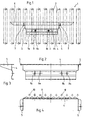
- FIG. 1 a portion of a radiator 1 with a plurality of parallel, vertically extending, tubular radiator elements 2 is shown schematically.
- an inventive fastening system is arranged.
- This fastening system consists of two anchoring elements 3, which have each been introduced into a space between two adjacent radiator elements 2 and attack after rotation by 90 ° respectively to the two adjacent radiator elements 2 and by attaching to a strip-shaped support element 4 were clamped with the radiator elements 2.
- the operation of the anchoring elements will be described later with reference to FIG. 9 in more detail.
- On the strip-shaped support member 4 holding elements 5 are arranged in the form of elbows respectively in the end regions of its horizontal extension. These angle pieces have a substantially parallel to the radiator elements 2 extending portion which is connected to the support member 4.
- Another section extends in each case substantially horizontally, orthogonal to the first-mentioned sections and forms a bearing surface for an object to be connected to the fastening system in the form of a tray table 6.
- the two angle pieces are aligned so that the substantially horizontally extending portions in a are arranged horizontally extending plane. On the so arranged portions of the angle pieces 5 of the tray 6 is placed and secured by screws 7 to the mounting system.
- the strip-shaped support element 4 is connected to the anchoring elements 3 via screws 7, which are guided through bores 8 a, 8 b. Further holes 9a and 9b are provided on the strip-shaped support member such that they are displaced by the holes 8a and 8b respectively by half the distance between two extending in the spaces between the radiator elements perpendicular bisector.
- FIG. 2 is a view of the fastening system shown in Fig. 1 is shown.
- the anchoring elements are not shown, and a connected to the fastening system object is not shown here.
- Fig. 3 is a side view from the right of the strip-shaped support member 4 shown in Fig. 2 with the connected to the support member 4 elbow 5 is shown.
- the strip-shaped support element 4 is a component formed from a profile strip.
- FIG. 4 shows a top view of the strip-type carrier element shown in FIG. 2 with the angle pieces 5 connected to the carrier element 4 It is clear from this figure that in the region of the radiator elements indicated by crosses 10, the contact surface 11 of the strip-shaped supporting element 4, which bears against the radiator elements, follows in its contour the negative of the contour formed by the radiator elements. By this configuration, a particularly good and safe concern of the strip-shaped support member 4 is ensured on the radiator elements of the radiator.
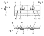
- Fig. 5 the view of a second embodiment of a strip-shaped support member 4 is shown with holding elements arranged thereon.
- the holding elements in the form of hooks 13 are formed.
- the strip-shaped support member 12 is in this case formed analogous to the strip-shaped support member 4 of the previous embodiment.
- the hooks shown here serve to receive an object to be fastened, e.g. a mirror, arranged counterpart, so as to connect the object with the fastening system.
- the strip-shaped support element 12 of the second embodiment has the same configuration as the strip-shaped support element 4 of the first embodiment.
- the two embodiments differ only in the holding elements connected to the support elements 4 and 12, which are in the case of the first embodiment, angle pieces 5 and in the case of the second embodiment, hooks 13.
- any further possible holding elements for example. Eyelets, mounting rails or the like on a strip-shaped support element can be arranged.
- Such a fastening system according to the invention can be constructed simply and modularly from basic elements adapted to the respective radiator, that is to say anchoring elements as well as support elements and support elements to be fastened to the object to be connected to the fastening system, eg hooks 13 or angle pieces 5.
- a radiator 1 is shown with radiator elements 2, on which both a fastening system in the manner of the first embodiment and two fastening systems are arranged in the manner of the second embodiment.
- the anchoring elements 3 and 18 as they are used for the fastening systems according to the first and the second embodiment are identical.
- a mirror 19 provided with hook elements is hooked into the hook 13 arranged on the strip-shaped support elements 12.
- a damping buffer 20 ensures that the mirror is buffered at a pressure load across its vertical extent and can not bend in the direction of the radiator and then break.
- FIG. 9 shows a detail enlargement of the area designated IX in FIG. 8.
- An armature 24 whose dimensions are chosen so that it can be introduced in the intermediate space between two radiator elements in an upright position, ie aligned with its longitudinal axis parallel to the radiator elements and then rotated by 90 °, the two adjacent radiator elements engages behind.
- a screw 21 is guided through an opening located in the fastening element 12, which extends in the further course through an opening arranged in the armature 24.
- a nut 22 is then applied to the screw to generate by tightening the screw 21 relative to the nut 22, a tensile force of the armature 24 in the direction of the strip-shaped support member 12.
- a spiral spring 23 is arranged in the region between the support element 12 and the armature 24, which one of the forces caused by tightening the screw pulling force counteracting pressure force causes, and thus a fuse of the nut 21 applied to the nut 22.
- FIG. 9 also shows that the mirror 19 by means of a hook member 26, which may, for example, be formed like a strip, is hooked into the integrally formed on the strip-shaped support member 12 hook 13.
- a hook member 26 which may, for example, be formed like a strip
Landscapes
- Engineering & Computer Science (AREA)
- Physics & Mathematics (AREA)
- Thermal Sciences (AREA)
- Chemical & Material Sciences (AREA)
- Combustion & Propulsion (AREA)
- Mechanical Engineering (AREA)
- General Engineering & Computer Science (AREA)
- Clamps And Clips (AREA)
- Connection Of Plates (AREA)
- Gripping Jigs, Holding Jigs, And Positioning Jigs (AREA)
- Details Of Heat-Exchange And Heat-Transfer (AREA)
Claims (8)
- Système de fixation pour la fixation d'objets (17, 19) sur un radiateur (1) avec plusieurs éléments de radiateur tubulaires (2) parallèles, composé :- d'éléments d'ancrage (3, 18) pouvant être reliés de manière amovible au radiateur (1),- d'au moins un élément portant (4, 12) en forme de bande, perpendiculaire aux éléments de radiateur (2) lorsque le système de fixation est disposé sur le radiateur (1), et relié de manière amovible aux éléments d'ancrage (3, 18), et- avec des éléments de maintien (5, 13) reliés à l'élément portant (4, 12) et destinés à recevoir l'objet (7, 19) à fixer,caractérisé en ce que l'élément portant (4, 12) en forme de bande est conformé de manière à reposer sur le radiateur (1) lorsque le système de fixation est fixé au radiateur (1) par une surface de contact (11, 17) et présente le long de sa surface de contact (11, 17) reposant sur le radiateur (1) un contour correspondant à la forme en négatif de la surface du radiateur faisant face à l'élément de fixation, et en ce que cette surface de fixation (11, 17) ayant un tel contour est en prise avec la surface du radiateur faisant face à l'élément portant (4, 12).
- Système de fixation selon la revendication 1, caractérisé en ce qu'il est conformé de manière à pouvoir être positionné sur une face du radiateur (1) tournée vers la pièce à chauffer.
- Système de fixation selon l'une quelconque des revendications 1 ou 2, caractérisé en ce que les éléments d'ancrage (3, 18) sont conformés de façon à pouvoir être assemblés au radiateur (1) par serrage entre deux éléments de radiateur (2) contigus.
- Système de fixation selon l'une quelconque des revendications 1 à 3, caractérisé en ce que l'élément portant (4, 12) relié aux éléments d'ancrage (3, 18) est conformé de façon à pouvoir être déplacé perpendiculairement aux éléments de radiateur (2) par rapport à ceux-ci et aux éléments d'ancrage.
- Système de fixation selon l'une quelconque des revendications 1 à 4, caractérisé en ce qu'aussi bien le contour de surface du radiateur faisant face à l'élément portant (4, 12) que le contour de surface de l'élément portant (4, 12) en forme de bande reposant le long de la surface de contact (11, 17) ont une structure à répétition périodique.
- Système de fixation selon l'une quelconque des revendications 1 à 5, caractérisé en ce qu'avec des éléments d'ancrage (3, 18) et des éléments portants (4, 12) identiques, des éléments de maintien (5, 13) adaptés aux objets (6, 19) à fixer sont disposés sur les éléments portants (4, 12).
- Système de fixation selon l'une quelconque des revendications 1 à 6, caractérisé en ce que les éléments de maintien (5, 13) sont fixés aux éléments portants (4, 12).
- Système de fixation selon l'une quelconque des revendications 1 à 7, caractérisé en ce qu'il comporte au moins un élément de fixation (7, 25) qui assure la liaison entre l'élément de maintien (5, 13) et l'objet (6, 19) à fixer.
Applications Claiming Priority (2)
| Application Number | Priority Date | Filing Date | Title |
|---|---|---|---|
| DE29920009U DE29920009U1 (de) | 1999-11-15 | 1999-11-15 | Befestigungssystem zum Befestigen von Gegenständen an einem Heizkörper |
| DE29920009U | 1999-11-15 |
Publications (3)
| Publication Number | Publication Date |
|---|---|
| EP1102011A2 EP1102011A2 (fr) | 2001-05-23 |
| EP1102011A3 EP1102011A3 (fr) | 2002-12-04 |
| EP1102011B1 true EP1102011B1 (fr) | 2006-07-26 |
Family
ID=8081598
Family Applications (1)
| Application Number | Title | Priority Date | Filing Date |
|---|---|---|---|
| EP00121899A Expired - Lifetime EP1102011B1 (fr) | 1999-11-15 | 2000-10-07 | Système pour fixer des objets à un radiateur |
Country Status (3)
| Country | Link |
|---|---|
| EP (1) | EP1102011B1 (fr) |
| AT (1) | ATE334350T1 (fr) |
| DE (2) | DE29920009U1 (fr) |
Family Cites Families (7)
| Publication number | Priority date | Publication date | Assignee | Title |
|---|---|---|---|---|
| CH613766A5 (en) * | 1975-04-12 | 1979-10-15 | Bottermann Wilhelm Wibo Werk | Set of structural elements for a radiator cladding |
| DE3209459A1 (de) * | 1982-03-16 | 1983-09-29 | Ludwig 4600 Dortmund Kalka | Aufhaengungsvorrichtung zur befestigung einer heizkoerperverkleidung an der vorderseite eines heizkoerpers |
| IT221662Z2 (it) * | 1989-12-21 | 1994-07-25 | Irsap Irsol Srl 29 | Mensola multiuso. |
| IT221142Z2 (it) * | 1990-02-16 | 1994-02-16 | Irsap Irsol Srl 29 | Mensola multiuso. |
| CH682245A5 (fr) * | 1991-07-12 | 1993-08-13 | Breitenmoser & Keller Ag Bremo | |
| CH689166A5 (de) * | 1994-12-22 | 1998-11-13 | Walter Steiner | Waeschetrockner sowie Radiator mit einem Waeschetrockner. |
| ATE252172T1 (de) * | 1997-08-07 | 2003-11-15 | Kermi Gmbh | Bewegbarer halteabschnitt für heizkörper bzw. heizkörper mit diesem |
-
1999
- 1999-11-15 DE DE29920009U patent/DE29920009U1/de not_active Expired - Lifetime
-
2000
- 2000-10-07 DE DE50013225T patent/DE50013225D1/de not_active Expired - Lifetime
- 2000-10-07 AT AT00121899T patent/ATE334350T1/de active
- 2000-10-07 EP EP00121899A patent/EP1102011B1/fr not_active Expired - Lifetime
Also Published As
| Publication number | Publication date |
|---|---|
| DE50013225D1 (de) | 2006-09-07 |
| EP1102011A3 (fr) | 2002-12-04 |
| ATE334350T1 (de) | 2006-08-15 |
| EP1102011A2 (fr) | 2001-05-23 |
| DE29920009U1 (de) | 2000-01-05 |
Similar Documents
| Publication | Publication Date | Title |
|---|---|---|
| DE69111489T2 (de) | Starres transversales Bindeglied zwischen zwei Wirbelsäulenstützstäben. | |
| EP1317631B1 (fr) | Piece de liaison pour rails de montage | |
| DE69934733T2 (de) | Vorrichtung und Verfahren zum Befestigen einer Gewindestange an einer Profilschiene | |
| EP0403427B1 (fr) | Dispositif d'abloquage pour pièces devant être usinées sur une machine-outil | |
| DE3590456C2 (de) | Klemmvorrichtung | |
| EP2416042B1 (fr) | Dispositif de suspension réglable | |
| DE3801103A1 (de) | Befestigungsvorrichtung fuer einstellbare frontblenden von schubladen | |
| DE9007599U1 (de) | Geräteträger | |
| EP1312852B1 (fr) | Dispositif pour la formation d'une paroi support pour écrans plats | |
| DE69210796T3 (de) | Klammer, insbesondere zur Befestigung von Heizkörpern | |
| EP1102011B1 (fr) | Système pour fixer des objets à un radiateur | |
| EP0417177B1 (fr) | Systeme de rayonnage | |
| EP3991921B1 (fr) | Agencement de retenue pour une structure de montage, ainsi que système de rangement doté de l'agencement de retenue | |
| DE69406496T2 (de) | Lösbare Verbindung für Büromöbel | |
| EP1624198A2 (fr) | Ferrrure d'assemblage pour panneaux, notamment pour planches d'étagères | |
| DE202017107484U1 (de) | Tragvorrichtung mit einem Tragarm zum Tragen eines Gegenstandes | |
| DE19527280A1 (de) | Zugentlastung für Leitungen | |
| DE4229370A1 (de) | Halteklammer zur axial verschiebbaren Befestigung von Stäben | |
| CH368599A (de) | Versetzbare Glaszwischenwand | |
| DE202017101918U1 (de) | Haltevorrichtung, insbesondere für Tablet-PCs | |
| DE102021006385A1 (de) | Wandbefestigungssystem mit Schiene und Trägerelement | |
| EP1851448A1 (fr) | Systeme de fixation pour au moins un composant fluidique d'un ensemble de chromatographie | |
| DE10319955B4 (de) | Verstelleinrichtung | |
| EP4528190A1 (fr) | Dispositif de support pour un tiroir extractible dans un réfrigérateur | |
| EP0187175A1 (fr) | Dispositif de fixation pour des éléments d'étagère |
Legal Events
| Date | Code | Title | Description |
|---|---|---|---|
| PUAI | Public reference made under article 153(3) epc to a published international application that has entered the european phase |
Free format text: ORIGINAL CODE: 0009012 |
|
| AK | Designated contracting states |
Kind code of ref document: A2 Designated state(s): AT BE CH CY DE DK ES FI FR GB GR IE IT LI LU MC NL PT SE |
|
| AX | Request for extension of the european patent |
Free format text: AL;LT;LV;MK;RO;SI |
|
| PUAL | Search report despatched |
Free format text: ORIGINAL CODE: 0009013 |
|
| AK | Designated contracting states |
Kind code of ref document: A3 Designated state(s): AT BE CH CY DE DK ES FI FR GB GR IE IT LI LU MC NL PT SE |
|
| AX | Request for extension of the european patent |
Free format text: AL;LT;LV;MK;RO;SI |
|
| 17P | Request for examination filed |
Effective date: 20030603 |
|
| AKX | Designation fees paid |
Designated state(s): AT BE CH CY DE DK ES FI FR GB GR IE IT LI LU MC NL PT SE |
|
| GRAP | Despatch of communication of intention to grant a patent |
Free format text: ORIGINAL CODE: EPIDOSNIGR1 |
|
| GRAS | Grant fee paid |
Free format text: ORIGINAL CODE: EPIDOSNIGR3 |
|
| GRAA | (expected) grant |
Free format text: ORIGINAL CODE: 0009210 |
|
| AK | Designated contracting states |
Kind code of ref document: B1 Designated state(s): AT BE CH CY DE DK ES FI FR GB GR IE IT LI LU MC NL PT SE |
|
| PG25 | Lapsed in a contracting state [announced via postgrant information from national office to epo] |
Ref country code: IT Free format text: LAPSE BECAUSE OF FAILURE TO SUBMIT A TRANSLATION OF THE DESCRIPTION OR TO PAY THE FEE WITHIN THE PRE;WARNING: LAPSES OF ITALIAN PATENTS WITH EFFECTIVE DATE BEFORE 2007 MAY HAVE OCCURRED AT ANY TIME BEFORE 2007. THE CORRECT EFFECTIVE DATE MAY BE DIFFERENT FROM THE ONE RECORDED.SCRIBED TIME-LIMIT Effective date: 20060726 Ref country code: IE Free format text: LAPSE BECAUSE OF FAILURE TO SUBMIT A TRANSLATION OF THE DESCRIPTION OR TO PAY THE FEE WITHIN THE PRESCRIBED TIME-LIMIT Effective date: 20060726 Ref country code: FI Free format text: LAPSE BECAUSE OF FAILURE TO SUBMIT A TRANSLATION OF THE DESCRIPTION OR TO PAY THE FEE WITHIN THE PRESCRIBED TIME-LIMIT Effective date: 20060726 Ref country code: NL Free format text: LAPSE BECAUSE OF FAILURE TO SUBMIT A TRANSLATION OF THE DESCRIPTION OR TO PAY THE FEE WITHIN THE PRESCRIBED TIME-LIMIT Effective date: 20060726 |
|
| REG | Reference to a national code |
Ref country code: GB Ref legal event code: FG4D Free format text: NOT ENGLISH |
|
| REG | Reference to a national code |
Ref country code: CH Ref legal event code: EP |
|
| REG | Reference to a national code |
Ref country code: IE Ref legal event code: FG4D Free format text: LANGUAGE OF EP DOCUMENT: GERMAN |
|
| REF | Corresponds to: |
Ref document number: 50013225 Country of ref document: DE Date of ref document: 20060907 Kind code of ref document: P |
|
| REG | Reference to a national code |
Ref country code: CH Ref legal event code: NV Representative=s name: E. BLUM & CO. PATENTANWAELTE |
|
| PG25 | Lapsed in a contracting state [announced via postgrant information from national office to epo] |
Ref country code: DK Free format text: LAPSE BECAUSE OF FAILURE TO SUBMIT A TRANSLATION OF THE DESCRIPTION OR TO PAY THE FEE WITHIN THE PRESCRIBED TIME-LIMIT Effective date: 20061026 Ref country code: SE Free format text: LAPSE BECAUSE OF FAILURE TO SUBMIT A TRANSLATION OF THE DESCRIPTION OR TO PAY THE FEE WITHIN THE PRESCRIBED TIME-LIMIT Effective date: 20061026 |
|
| PG25 | Lapsed in a contracting state [announced via postgrant information from national office to epo] |
Ref country code: MC Free format text: LAPSE BECAUSE OF NON-PAYMENT OF DUE FEES Effective date: 20061031 |
|
| PG25 | Lapsed in a contracting state [announced via postgrant information from national office to epo] |
Ref country code: ES Free format text: LAPSE BECAUSE OF FAILURE TO SUBMIT A TRANSLATION OF THE DESCRIPTION OR TO PAY THE FEE WITHIN THE PRESCRIBED TIME-LIMIT Effective date: 20061106 |
|
| GBT | Gb: translation of ep patent filed (gb section 77(6)(a)/1977) |
Effective date: 20061020 |
|
| PG25 | Lapsed in a contracting state [announced via postgrant information from national office to epo] |
Ref country code: PT Free format text: LAPSE BECAUSE OF FAILURE TO SUBMIT A TRANSLATION OF THE DESCRIPTION OR TO PAY THE FEE WITHIN THE PRESCRIBED TIME-LIMIT Effective date: 20061226 |
|
| NLV1 | Nl: lapsed or annulled due to failure to fulfill the requirements of art. 29p and 29m of the patents act | ||
| ET | Fr: translation filed | ||
| REG | Reference to a national code |
Ref country code: IE Ref legal event code: FD4D |
|
| PLBE | No opposition filed within time limit |
Free format text: ORIGINAL CODE: 0009261 |
|
| STAA | Information on the status of an ep patent application or granted ep patent |
Free format text: STATUS: NO OPPOSITION FILED WITHIN TIME LIMIT |
|
| 26N | No opposition filed |
Effective date: 20070427 |
|
| REG | Reference to a national code |
Ref country code: CH Ref legal event code: PFA Owner name: ZEHNDER VERKAUFS- UND VERWALTUNGS AG Free format text: ZEHNDER VERKAUFS- UND VERWALTUNGS AG#MOORTALSTRASSE 1#5722 GRAENICHEN (CH) -TRANSFER TO- ZEHNDER VERKAUFS- UND VERWALTUNGS AG#MOORTALSTRASSE 1#5722 GRAENICHEN (CH) |
|
| PG25 | Lapsed in a contracting state [announced via postgrant information from national office to epo] |
Ref country code: GR Free format text: LAPSE BECAUSE OF FAILURE TO SUBMIT A TRANSLATION OF THE DESCRIPTION OR TO PAY THE FEE WITHIN THE PRESCRIBED TIME-LIMIT Effective date: 20061027 |
|
| PG25 | Lapsed in a contracting state [announced via postgrant information from national office to epo] |
Ref country code: LU Free format text: LAPSE BECAUSE OF NON-PAYMENT OF DUE FEES Effective date: 20061007 |
|
| PG25 | Lapsed in a contracting state [announced via postgrant information from national office to epo] |
Ref country code: CY Free format text: LAPSE BECAUSE OF FAILURE TO SUBMIT A TRANSLATION OF THE DESCRIPTION OR TO PAY THE FEE WITHIN THE PRESCRIBED TIME-LIMIT Effective date: 20060726 |
|
| PGFP | Annual fee paid to national office [announced via postgrant information from national office to epo] |
Ref country code: AT Payment date: 20101014 Year of fee payment: 11 |
|
| PGFP | Annual fee paid to national office [announced via postgrant information from national office to epo] |
Ref country code: GB Payment date: 20101021 Year of fee payment: 11 Ref country code: IT Payment date: 20101025 Year of fee payment: 11 |
|
| PGFP | Annual fee paid to national office [announced via postgrant information from national office to epo] |
Ref country code: FR Payment date: 20111103 Year of fee payment: 12 Ref country code: BE Payment date: 20111013 Year of fee payment: 12 Ref country code: CH Payment date: 20111024 Year of fee payment: 12 |
|
| REG | Reference to a national code |
Ref country code: AT Ref legal event code: MM01 Ref document number: 334350 Country of ref document: AT Kind code of ref document: T Effective date: 20111007 |
|
| PG25 | Lapsed in a contracting state [announced via postgrant information from national office to epo] |
Ref country code: AT Free format text: LAPSE BECAUSE OF NON-PAYMENT OF DUE FEES Effective date: 20111007 |
|
| BERE | Be: lapsed |
Owner name: *ZEHNDER VERKAUFS- UND VERWALTUNGS A.G. Effective date: 20121031 |
|
| REG | Reference to a national code |
Ref country code: CH Ref legal event code: PL |
|
| GBPC | Gb: european patent ceased through non-payment of renewal fee |
Effective date: 20121007 |
|
| REG | Reference to a national code |
Ref country code: FR Ref legal event code: ST Effective date: 20130628 |
|
| PG25 | Lapsed in a contracting state [announced via postgrant information from national office to epo] |
Ref country code: BE Free format text: LAPSE BECAUSE OF NON-PAYMENT OF DUE FEES Effective date: 20121031 Ref country code: LI Free format text: LAPSE BECAUSE OF NON-PAYMENT OF DUE FEES Effective date: 20121031 Ref country code: CH Free format text: LAPSE BECAUSE OF NON-PAYMENT OF DUE FEES Effective date: 20121031 Ref country code: GB Free format text: LAPSE BECAUSE OF NON-PAYMENT OF DUE FEES Effective date: 20121007 |
|
| PG25 | Lapsed in a contracting state [announced via postgrant information from national office to epo] |
Ref country code: IT Free format text: LAPSE BECAUSE OF NON-PAYMENT OF DUE FEES Effective date: 20121007 Ref country code: FR Free format text: LAPSE BECAUSE OF NON-PAYMENT OF DUE FEES Effective date: 20121031 |
|
| REG | Reference to a national code |
Ref country code: DE Ref legal event code: R082 Ref document number: 50013225 Country of ref document: DE Representative=s name: STENGER WATZKE RING INTELLECTUAL PROPERTY, DE Ref country code: DE Ref legal event code: R081 Ref document number: 50013225 Country of ref document: DE Owner name: ZEHNDER GROUP INTERNATIONAL AG, CH Free format text: FORMER OWNER: ZEHNDER VERKAUFS- UND VERWALTUNGS-AG, GRAENICHEN, CH Ref country code: DE Ref legal event code: R082 Ref document number: 50013225 Country of ref document: DE Representative=s name: RAUSCH WANISCHECK-BERGMANN BRINKMANN PARTNERSC, DE |
|
| REG | Reference to a national code |
Ref country code: DE Ref legal event code: R082 Ref document number: 50013225 Country of ref document: DE Representative=s name: RAUSCH WANISCHECK-BERGMANN BRINKMANN PARTNERSC, DE |
|
| PGFP | Annual fee paid to national office [announced via postgrant information from national office to epo] |
Ref country code: DE Payment date: 20181019 Year of fee payment: 19 |
|
| REG | Reference to a national code |
Ref country code: DE Ref legal event code: R119 Ref document number: 50013225 Country of ref document: DE |
|
| PG25 | Lapsed in a contracting state [announced via postgrant information from national office to epo] |
Ref country code: DE Free format text: LAPSE BECAUSE OF NON-PAYMENT OF DUE FEES Effective date: 20200501 |