EP1101451A2 - Verfahren zur Herstellung einer Bohrhilfe für ein Zahnimplantat - Google Patents
Verfahren zur Herstellung einer Bohrhilfe für ein Zahnimplantat Download PDFInfo
- Publication number
- EP1101451A2 EP1101451A2 EP00123977A EP00123977A EP1101451A2 EP 1101451 A2 EP1101451 A2 EP 1101451A2 EP 00123977 A EP00123977 A EP 00123977A EP 00123977 A EP00123977 A EP 00123977A EP 1101451 A2 EP1101451 A2 EP 1101451A2
- Authority
- EP
- European Patent Office
- Prior art keywords
- ray
- jaw
- teeth
- measurement data
- dimensional optical
- Prior art date
- Legal status (The legal status is an assumption and is not a legal conclusion. Google has not performed a legal analysis and makes no representation as to the accuracy of the status listed.)
- Granted
Links
Images

Classifications
-
- A—HUMAN NECESSITIES
- A61—MEDICAL OR VETERINARY SCIENCE; HYGIENE
- A61C—DENTISTRY; APPARATUS OR METHODS FOR ORAL OR DENTAL HYGIENE
- A61C1/00—Dental machines for boring or cutting ; General features of dental machines or apparatus, e.g. hand-piece design
- A61C1/08—Machine parts specially adapted for dentistry
- A61C1/082—Positioning or guiding, e.g. of drills
- A61C1/084—Positioning or guiding, e.g. of drills of implanting tools
-
- A—HUMAN NECESSITIES
- A61—MEDICAL OR VETERINARY SCIENCE; HYGIENE
- A61B—DIAGNOSIS; SURGERY; IDENTIFICATION
- A61B6/00—Apparatus or devices for radiation diagnosis; Apparatus or devices for radiation diagnosis combined with radiation therapy equipment
- A61B6/50—Apparatus or devices for radiation diagnosis; Apparatus or devices for radiation diagnosis combined with radiation therapy equipment specially adapted for specific body parts; specially adapted for specific clinical applications
- A61B6/506—Apparatus or devices for radiation diagnosis; Apparatus or devices for radiation diagnosis combined with radiation therapy equipment specially adapted for specific body parts; specially adapted for specific clinical applications for diagnosis of nerves
Definitions
- the invention relates to a method for Production of a drilling aid for the exact attachment of the Guide hole for a dental implant, the Guide hole for the implant still in the jaw existing teeth is aligned.
- WO 99/32045 discloses a process for the production a dental drilling aid for implants.
- the in procedure proposed in this publication is based on a picture of the jaw with reference to a Imprint area a three-dimensional computer image modeled.
- Computer graphics will have at least one well position determined, their position in three dimensions is specified, including the Borehole endpoint and the borehole length in relation to the jaw print.
- On one A first surface is provided for the drill body corresponds to the impression area of the jaw.
- Drill body for each of the previously imported Borehole coordinate sets a drill guide base prepared with according to the using the Jaw section determined the borehole position and Borehole orientation.
- the position of the borehole and the Drill hole orientation based on one from the jawbone taken impression determined.
- Dental implants are the shape and size of the Precisely planned implants using X-rays.
- the position of the implant in the jaw becomes as precise as possible predetermined.
- it is however difficult to determine the position of the pilot hole Drilling to determine exactly because the on the Information contained in X-ray images is not exact on the optical images that the doctor has when drilling sees, can be transferred.
- the doctor is leaving on his experience, especially what the location and the Course of the running in the jawbone Affects nerve strands. This is how the unsatisfactory arises
- the result is that implants are planned very precisely and are manufactured, their positioning in the jaw area but has so far been based on empirical values that can vary greatly individually.
- a drilling aid in the form of a Drilling template can be provided that the guide hole on the for attaching the Implants based on the position of neighboring teeth Contains position.
- the dentist follows through by Help given for the drilling aid Guide hole and is therefore safe, not the im To meet the nerve strands that run through the jaw Location is not from the three-dimensional Surface measurement emerges, but from the X-ray is known.
- proposed procedure can be the x-ray a panoramic slice, a tomosynthetic Recording or one on computed tomography Paths generated recording.
- the three-dimensional optical measurement of visible Surfaces are preferred to the occlusal surfaces Implant of adjacent teeth still present in the jaw measured. From the correlation of the measurement data sets of the X-ray and the measurement data records of the three-dimensional optical recording, are the visible and invisible to the human eye - for example the course of the nerves - conditions in the Known implant area and allow the safe Drill a guide hole in the jaw.
- markers can be used - for example bodies formed as spheres - are both in the x-ray and in the three-dimensional optical image of the jaw visible. By aligning the markers itself in a simple way by the user interactive correlation of the x-ray with the three-dimensional optical shot of the visible Create structures.
- a correlation of the X-ray measurement data sets and three-dimensional optical recording can also by measuring data records of the three - dimensional optical picture assuming Standard X-ray absorption values in Pseudo-X-rays can be converted.
- the actual x-ray and the Pseudo-X-rays can be made up of several Aligning the directions, for example using longitudinal and transverse Cuts in the panoramic x-ray.
- a Correlation can also be done by at least partly from the x-rays Surface shapes are extracted as they are in the optical recording and then with the data the optical recording are made to coincide. This can be done automatically or interactively happen.
- the implant can be known Be determined and positioned in a way. Based on obtained information about the surface structure, d. H. the occlusal surfaces of adjacent teeth can be one Implantation aid in the form of a drilling template a CAD / CAM unit, where on the shape of the occlusal surfaces existing neighboring teeth are reproduced in the negative.
- the drilling aid contains a hole that the guide of the Dentist's drill bit for the hole for attachment of the implant.
- the negative forms of Occlusal surfaces allow clear positioning the drilling template in the patient's mouth.
- Panoramic slice 1 is shown as X-ray of a panoramic slice shown the upper and lower jaw area in one flat representation.
- Panoramic slice is also tomosynthetic X-ray, as well as a computed tomography X-ray conceivable.
- Fig. 2 shows schematically a three-dimensional optical image of a molar 2, in which the Surface structure, the occlusal surface 3 using a three-dimensional coordinate system 4 is measured.
- an entire jaw branch can just as well be measured, be it in the upper or lower jaw.
- the X-ray image 5 or the three-dimensional optical Recording 10 can be saved as measurement data sets and lay down; the respective measurement data records for the recording 5, 10 can be based on certain default criteria correlate with each other.
- the correlation which can be done in different ways, links the invisible conditions at the implant site 9, which do not show themselves to the human eye, with the conditions recognizable for the dentist.
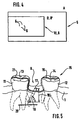
- the correlation can take place on the one hand by superimposing an X-ray image A with a three-dimensional image B (cf. FIG. 5), and fixed points can be generated using markers 6 attached to the teeth 2, as a result of which an X-ray image A and a three-dimensional B overlap one another can be brought and a correlation of the two measurement data sets can take place.
- markers 6, which can be attached to the teeth 2 a pseudo-X-ray image B ' , 8 can be generated from the surface data of the three-dimensional image 10, assuming standard X-ray absorption values and the origin theory of the respective X-ray image.
- the present x-ray image 5 and the pseudo-x-ray image 8 can be brought into register with one another by the user in an interactive step. If the user carries out the correlation from several directions, the correlation of the X-ray image 5 with the three-dimensional image 10 is fully determined. If a panoramic slice is selected as the x-ray, the user can achieve this with longitudinal and transverse cuts through the panoramic slice. This would cover the X and Y directions of a coordinate system 4.
- the position is in the x-ray image 5 according to FIG planned of the implant, taking its position in the jaw 1 on one, but usually from two directions seen, fixed. From X-ray A, Reference number 5 is the course of the nerve 20 in the lower region of the jaw 1 known, based on this Position the borehole depth 18 (see FIG. 5) planned can be.
- the correlation of the x-ray 5 with the three-dimensional optical recording 10 allows one Include the position adjacent to the implant 9 arranged teeth 11 and 12. Their positions are both from the X-ray 5 and from the three-dimensional optical recording 10 known. Out the three-dimensional optical recording 10 result additionally the occlusal surface structures 13 and 14 of the adjacent teeth 11 and 12. Since the X-ray and the 3D image of each other correlated is the location of the planned implant known relative to the occlusal surfaces of the neighboring teeth.
- a CAD / CAM machine is based on the measurement data able to drill the template with the negative the occlusal surfaces and guide barrel for the drill manufacture.
- a fixation of such a type of drilling aid received 16 is carried out by means of a releasable adhesive layer 21 the occlusal surfaces 13 and 14 adjacent teeth 11 and 12, which limit the implant position 9.
- the Drilling aid 16 or drilling template can be in advantageously on a Precision machine tool that is three-dimensional can be operated, manufactured, on the can also make dentures.
- the exact positioning of the drilling aid 16 with respect to the jaw section 15 of the implant position 9 achieved in that the negative form of the drilling aid 16th on the occlusal surfaces 13, 14 of the adjacent teeth 11 and 12 touches down.
- the position of the pilot hole 17 predefined on the surface of the drilling aid 16, likewise the inclination 19 in which he has to start the drill.
- the Drilling depth 18 is from the correlation of the dentist Measurement records from X-ray 5, be it as Panoramic slice shot held or as one Tomosynthetic image available, determined and is transferred to the drilling template as a stop. Since the position on the top of the drilling aid 16 of the guide hole 17, the dentist can Make a hole in the jaw 1 with the certainty that for the attachment of the implant between the Neighboring teeth 11 and 12 optimal pilot hole position to have chosen.
Landscapes
- Health & Medical Sciences (AREA)
- Oral & Maxillofacial Surgery (AREA)
- Dentistry (AREA)
- Epidemiology (AREA)
- Life Sciences & Earth Sciences (AREA)
- Animal Behavior & Ethology (AREA)
- General Health & Medical Sciences (AREA)
- Public Health (AREA)
- Veterinary Medicine (AREA)
- Apparatus For Radiation Diagnosis (AREA)
- Dental Prosthetics (AREA)
- Dental Tools And Instruments Or Auxiliary Dental Instruments (AREA)
Abstract
Description
- Das Herstellen von Röntgenaufnahmen des Kiefers und das Erzeugen eines entsprechenden Meßdatensatzes,
- die dreidimensionale optische Vermessung der sichtbaren Oberfläche von Kiefer und Zähnen und die Erzeugung eines entsprechenden Meßdatensatzes,
- der Korrelation der Meßdatensätze von Röntgenaufnahme und der Meßdatensätze der dreidimensionalen optischen Vermessung,
- der Planung des Implantattyps und der Implantatposition (Ort, Winkel) vorzugsweise anhand der Röntgendaten,
- dem Errechnen der Position (Ort, Winkel, Tiefe) des Implantatführungsloches relativ zu den erfaßten Oberflächen der Nachbarzähne,
- dem Erzeugen einer Bohrschablone, die die Negative der Oberflächen der Nachbarzähne und eine an vorbestimmter Stelle liegende Öffnung enthält.
- Figur 1
- Eine Panoramaschichtaufnahme in schematischer Form,
- Figur 2
- die Erzeugung einer dreidimensionalen optischen Aufnahme von sichtbaren Strukturen im Kiefer,
- Figur 3
- die Erzeugung einer Pseudoröntgenaufnahme aus einer dreidimensionalen Aufnahme sichtbarer Strukturen,
- Figur 4
- die Superposition von Röntgenaufnahme und dreidimensionaler optischer Aufnahme oder Pseudoröntgenaufnahme B' und
- Figur 5
- den für ein Implantat vorgesehenen Zwischenraum zwischen zwei benachbarten Zähnen und einer dort aufgenommenen Bohrhilfe.
- 1.
- Kiefer
- 2.
- Zahn
- 3.
- Okklusalfläche
- 4.
- Koordinatensystem
- 5.
- Röntgenaufnahme
- 6.
- Marker
- 7.
- Superposition
- 8.
- Pseudo-Röntgenaufnahme
- 9.
- Implantatposition
- 10.
- 3D-Aufnahme
- 11.
- benachbarter Zahn
- 12.
- benachbarter Zahn
- 13.
- Okklusalflächen
- 14.
- Okklusalflächen
- 15.
- Kieferabschnitt
- 16.
- Bohrhilfe
- 17.
- Führungslochposition
- 18.
- Bohrtiefe
- 19.
- Bohrungsneigung
- 20.
- Nerv
- 21.
- Haftschicht
- A
- Röntgenaufnahme
- B
- 3D-Aufnahme
- B'
- Pseudoröntgenaufnahme
Claims (10)
- Verfahren zur Erstellung einer Bohrhilfe (16) für ein Zahnimplantat mit nachfolgenden Verfahrensschritten:dem Herstellen von Röntgenaufnahmen (5) des Kiefers (1) und Erzeugen eines entsprechenden Meßdatensatzes,der dreidimensionalen optischen Vermessung der sichtbaren Oberfläche von Kiefer (1) und Zähnen (2) und Erzeugen eines entsprechenden Meßdatensatzes,der Korrelation der Meßdatensätze der Röntgenaufnahme (5) und der Meßdatensätze der dreidimensionalen optischen Vermessung (10) undder Bestimmung des optimalen Bohrloches für ein Implantat vorzugsweise aufgrund der Röntgenaufnahme,der Bestimmung eines Führungsloches in einer Bohrschablone (16) relativ zu den Oberflächen der Nachbarzähne aufgrund von Röntgenaufnahmen und optischer Vermessung.
- Verfahren gemäß Anspruch 1, dadurch gekennzeichnet, daß die Röntgenaufnahme (5) Panoramaschichtaufnahmen, tumosynthetische Aufnahme oder computertomographsiche Aufnahmen sind.
- Verfahren gemäß Anspruch 1, dadurch gekennzeichnet, daß die dreidimensional vermessene, sichtbare Oberfläche (13, 14) die Okklusalflächen benachbarter Zähne (11, 12) am Kiefer (1) sind.
- Verfahren gemäß Anspruch 1, dadurch gekennzeichnet, daß die Korrelation der Maßdatensätze von Röntgenaufnahme (5) und dreidimensionaler optischer Aufnahme (10) anhand von auf Zähnen (2) aufgebrachter Marker (6) erfolgt.
- Verfahren gemäß Anspruch 4, dadurch gekennzeichnet, daß die Marker (6) Kugeln sind.
- Verfahren gemäß Anspruch 1, dadurch gekennzeichnet, daß die Meßdatensätze der dreidimensionalen optischen Vermessung und unter Zugrundelegung von Standard-Röntgenabsorptionswerten und der Entstehungstheorie des jeweiligen Röntgenbildes in eine Pseudoröntgenaufnahme (8) umgerechnet werden.
- Verfahren gemäß der Ansprüche 1 und 6, dadurch gekennzeichnet, daß die Röntgenaufnahme (5) und die Pseudoröntgenaufnahme (8) aus mehreren Richtungen zur Deckung gebracht werden.
- Verfahren gemäß Anspruch 7, dadurch gekennzeichnet, daß es sich bei der Röntgenaufnahme (5) um mindestens zwei Einzelpanoramaaufnahmen handelt, die longitudinale und transversale Schnitte durch den Kiefer zeigen.
- Verfahren gemäß Anspruch 1, dadurch gekennzeichnet, daß die Bohrhilfe (16) auf einem dimensionsstabilen Material ausgeschliffen wird, wobei dieses die Form der Okklusalflächen (13, 14) von Nachbarzähnen (11, 12) der Implantierungsposition (9) im Negativ wiedergibt.
- Verfahren gemäß Anspruch 9, dadurch gekennzeichnet, daß die Bohrhilfe (16) eine Bohrungsposition (17) enthält, die zur Führung des Bohrers dient.
Priority Applications (1)
| Application Number | Priority Date | Filing Date | Title |
|---|---|---|---|
| DE50010094.2T DE50010094C5 (de) | 1999-11-03 | 2000-11-03 | Verfahren zur Herstellung einer Bohrhilfe für ein Zahnimplantat |
Applications Claiming Priority (2)
| Application Number | Priority Date | Filing Date | Title |
|---|---|---|---|
| DE19952962 | 1999-11-03 | ||
| DE19952962A DE19952962B4 (de) | 1999-11-03 | 1999-11-03 | Verfahren zur Herstellung einer Bohrhilfe für ein Zahnimplantat |
Publications (3)
| Publication Number | Publication Date |
|---|---|
| EP1101451A2 true EP1101451A2 (de) | 2001-05-23 |
| EP1101451A3 EP1101451A3 (de) | 2003-03-26 |
| EP1101451B1 EP1101451B1 (de) | 2005-04-20 |
Family
ID=7927818
Family Applications (1)
| Application Number | Title | Priority Date | Filing Date |
|---|---|---|---|
| EP00123977A Expired - Lifetime EP1101451B1 (de) | 1999-11-03 | 2000-11-03 | Verfahren zur Herstellung einer Bohrhilfe für ein Zahnimplantat |
Country Status (5)
| Country | Link |
|---|---|
| US (1) | US6319006B1 (de) |
| EP (1) | EP1101451B1 (de) |
| JP (2) | JP5124063B2 (de) |
| AT (1) | ATE293397T1 (de) |
| DE (2) | DE19952962B4 (de) |
Cited By (6)
| Publication number | Priority date | Publication date | Assignee | Title |
|---|---|---|---|---|
| DE10353913A1 (de) * | 2003-11-18 | 2005-06-02 | Straelen, Frank van, Dr. | Verfahren und Vorrichtung zum Herstellen einer navigierten Bohrschablone für die Einbringung von Zahnimplantatbohrungen |
| EP1449489A4 (de) * | 2001-10-31 | 2009-03-11 | Imagnosis Inc | Medizinisches simulationsgerät und verfahren zur kontrolle der 3-dimensionalen bildanzeige im medizinischen simulationsgerät |
| WO2012076574A3 (en) * | 2010-12-07 | 2012-08-09 | Sirona Dental Systems Gmbh | Method and system for designing and manufacturing custom dental preparation guides |
| EP2957251A1 (de) | 2014-06-19 | 2015-12-23 | R+K CAD CAM Technologie GmbH & Co. KG | Vorrichtung zur verwendung in einem verfahren zum herstellen einer zahnimplantatstruktur |
| DE102005040739B4 (de) | 2005-08-26 | 2019-06-06 | "Stiftung Caesar" (Center Of Advanced European Studies And Research) | Bohrschablone |
| DE102018204098A1 (de) | 2018-03-16 | 2019-09-19 | Sirona Dental Systems Gmbh | Bildausgabeverfahren während einer dentalen Anwendung und Bildausgabevorrichtung |
Families Citing this family (120)
| Publication number | Priority date | Publication date | Assignee | Title |
|---|---|---|---|---|
| DE19952962B4 (de) * | 1999-11-03 | 2004-07-01 | Sirona Dental Systems Gmbh | Verfahren zur Herstellung einer Bohrhilfe für ein Zahnimplantat |
| AR014089A1 (es) * | 2000-06-16 | 2001-02-07 | Ranalli Sebastian Luciano | Dispositivo para la planificacion y posterior colocacion de un implante dentario, metodo para planificar la correcta colocacion de un implante dentario queemplea dicho dispositivo y guia pretomografica y plantilla quirurgica obtenidas mediante dicho metodo |
| US6626667B2 (en) | 2002-01-16 | 2003-09-30 | Harold I. Sussman | Implant guide arrangement |
| DE10202378B4 (de) * | 2002-01-23 | 2005-07-21 | Dürr Dental GmbH & Co. KG | Dentales Behandlungsgerät |
| FR2836372B1 (fr) * | 2002-02-28 | 2004-06-04 | Obl | Procede et dispositif pour la mise en place d'implants dentaires |
| JP3820390B2 (ja) * | 2002-08-26 | 2006-09-13 | 株式会社アイキャット | 人工歯根埋入位置算出方法、人工歯根埋入位置算出装置、コンピュータプログラム及び記録媒体 |
| US7014461B2 (en) * | 2003-01-23 | 2006-03-21 | Tactile Technologies Llc | Hard tissue surface geometry determination |
| US7104795B2 (en) * | 2003-02-04 | 2006-09-12 | Michel Dadi | Method and device for determining position of dental implants |
| US20040166462A1 (en) | 2003-02-26 | 2004-08-26 | Align Technology, Inc. | Systems and methods for fabricating a dental template |
| ATE462369T1 (de) * | 2003-02-28 | 2010-04-15 | Materialise Dental Nv | Bohrschablone |
| CA2521241C (en) * | 2003-04-04 | 2012-01-24 | Xawex Ag | Process for producing dental prostheses |
| US6966772B2 (en) * | 2003-05-02 | 2005-11-22 | Leo J. Malin | Method of adjusting a drill bushing for a dental implant |
| US7044735B2 (en) * | 2003-05-02 | 2006-05-16 | Leo J. Malin | Method of installing a dental implant |
| EP1486900A1 (de) * | 2003-06-12 | 2004-12-15 | Materialise, Naamloze Vennootschap | Methode und System zur Herstellung einer chirurgischen Führungsschablone |
| US7097451B2 (en) * | 2003-11-14 | 2006-08-29 | Brian Tang | Thermoplastic surgical template for performing dental implant osteotomies and method thereof |
| GB0327822D0 (en) * | 2003-12-01 | 2003-12-31 | Materialise Nv | Method for manufacturing a prosthesis made prior to implant placement |
| DE102005005656B4 (de) * | 2004-06-08 | 2010-04-08 | Feith, Johan, Dr. | Dentalimplantat und Verfahren zum Herstellen eines Dentalimplantats |
| EP1621179A1 (de) | 2004-07-30 | 2006-02-01 | DENTSPLY DETREY GmbH | Laserhärtende polymerisierbare Zusammensetzung zum Schutz von Hartgewebe |
| US7322824B2 (en) * | 2004-08-17 | 2008-01-29 | Schmitt Stephen M | Design and manufacture of dental implant restorations |
| KR101235320B1 (ko) * | 2004-09-14 | 2013-02-21 | 오라티오 비.브이. | 미적인 임플란트 어버트먼트를 가지는 세라믹 치아임플란트의 제조방법 및 설치방법 |
| FR2881943A1 (fr) * | 2005-02-14 | 2006-08-18 | Jean Baptiste Charrier | Dispositif pour realiser des saignees dans la corticale osseuse d'une machoire et procede pour realiser ce dispositif |
| GB0514554D0 (en) * | 2005-07-15 | 2005-08-24 | Materialise Nv | Method for (semi-) automatic dental implant planning |
| EP1933757B1 (de) * | 2005-08-26 | 2017-03-29 | siCAT GmbH & Co. KG | Rohling als bohrschablone und zum registrieren von datensätzen |
| US8366442B2 (en) * | 2006-02-15 | 2013-02-05 | Bankruptcy Estate Of Voxelogix Corporation | Dental apparatus for radiographic and non-radiographic imaging |
| US8043091B2 (en) * | 2006-02-15 | 2011-10-25 | Voxelogix Corporation | Computer machined dental tooth system and method |
| EP2010090B1 (de) | 2006-03-24 | 2019-09-11 | Sicat GmbH & CO. KG | Verfahren zur herstellung von zahnersatzteilen |
| GB0609988D0 (en) * | 2006-05-19 | 2006-06-28 | Materialise Nv | Method for creating a personalized digital planning file for simulation of dental implant placement |
| US7530810B2 (en) * | 2006-08-30 | 2009-05-12 | Clement Milton A | Dental fixture implantation system and associated method |
| WO2008030965A2 (en) * | 2006-09-06 | 2008-03-13 | Voxelogix Corporation | Methods for the virtual design and computer manufacture of intra oral devices |
| JP2008073440A (ja) | 2006-09-25 | 2008-04-03 | Imagunooshisu Kk | インプラント植立ガイドの作製方法およびガイド用ブロック |
| US7835811B2 (en) * | 2006-10-07 | 2010-11-16 | Voxelogix Corporation | Surgical guides and methods for positioning artificial teeth and dental implants |
| WO2008083857A1 (en) | 2007-01-10 | 2008-07-17 | Nobel Biocare Services Ag | Method and system for dental planning and production |
| DE102007002144A1 (de) * | 2007-01-15 | 2008-07-17 | Aepsilon Rechteverwaltungs Gmbh | Verfahren betreffend Implantate sowie ein computerlesbares Medium und ein Computer |
| WO2008112925A2 (en) * | 2007-03-13 | 2008-09-18 | Voxelogix Corporation | Direct manufacture of dental and medical devices |
| ITBS20070040A1 (it) * | 2007-03-26 | 2008-09-27 | Studio Dentistico Dr Jacotti M | Metodo di realizzazione di una mascherina di guida per implantologia dentale, mascherina di guida cosi' ottenuta e dispositivo di riferimento per l'esecuzione del metodo |
| US8265949B2 (en) | 2007-09-27 | 2012-09-11 | Depuy Products, Inc. | Customized patient surgical plan |
| US9173662B2 (en) | 2007-09-30 | 2015-11-03 | DePuy Synthes Products, Inc. | Customized patient-specific tibial cutting blocks |
| US9138239B2 (en) | 2007-09-30 | 2015-09-22 | DePuy Synthes Products, Inc. | Customized patient-specific tibial cutting blocks |
| US8979855B2 (en) | 2007-09-30 | 2015-03-17 | DePuy Synthes Products, Inc. | Customized patient-specific bone cutting blocks |
| US8357111B2 (en) | 2007-09-30 | 2013-01-22 | Depuy Products, Inc. | Method and system for designing patient-specific orthopaedic surgical instruments |
| ES2802126T3 (es) * | 2007-09-30 | 2021-01-15 | Depuy Products Inc | Instrumento quirúrgico ortopédico personalizado específico de un paciente |
| WO2009046391A1 (en) | 2007-10-03 | 2009-04-09 | Bernard Gantes | Assisted dental implant treatment |
| TW200916060A (en) * | 2007-10-09 | 2009-04-16 | Pou Yuen Technology Co Ltd | Method for generating digital tooth implantation planning assisting element |
| US8246352B2 (en) | 2008-02-28 | 2012-08-21 | Akira Takebayashi | Surgical guide and a method for positioning a drill using the surgical guide |
| ES2739460T3 (es) * | 2008-03-19 | 2020-01-31 | Nobel Biocare Services Ag | Reposicionamiento de componentes relacionados con procedimientos quirúrgicos craneales en un paciente |
| KR101485882B1 (ko) | 2008-04-15 | 2015-01-26 | 바이오메트 쓰리아이 엘엘씨 | 정확한 뼈와 연조직 디지털 치아 모델의 형성 방법 |
| US8678819B2 (en) | 2008-05-20 | 2014-03-25 | Akira Takebayashi | Surgical guide, and a method for positioning a drill using the surgical guide |
| US8092215B2 (en) | 2008-05-23 | 2012-01-10 | Align Technology, Inc. | Smile designer |
| TW201000078A (en) * | 2008-06-26 | 2010-01-01 | Pou Yu Biotechnology Co Ltd | Manufacturing method for the guiding board of dental implant surgical operation |
| WO2010022479A2 (en) * | 2008-08-29 | 2010-03-04 | De Clerck Rene | Method and transfer element for manufacturing a superstructure and a corresponding template |
| US20110045431A1 (en) * | 2008-11-18 | 2011-02-24 | Groscurth Randall C | Bone screw linking device |
| US20110045432A1 (en) * | 2008-11-18 | 2011-02-24 | Groscurth Randall C | Simple linking device |
| CN102215779A (zh) * | 2008-11-18 | 2011-10-12 | Ibur有限责任公司 | 用于链接物理和数字数据以用于诊断、治疗计划、患者教育、通信、制造和数据传送目的的牙科装置和方法 |
| KR100970341B1 (ko) | 2008-12-19 | 2010-07-15 | 이준호 | 다목적 스텐트 및 그 제작 방법 |
| DE102009010699C5 (de) | 2009-02-27 | 2020-11-12 | Marcus Abboud | Bohrschablone zum Präparieren eines Patienten-Kieferknochens für ein medizinisches Zahn-Implantat |
| WO2014143014A1 (en) * | 2013-03-15 | 2014-09-18 | Triagenics, Llc | Therapeutic tooth bud ablation |
| US12514679B2 (en) | 2009-05-11 | 2026-01-06 | TriAgenics, Inc. | Therapeutic tooth bud ablation |
| CA2939821C (en) | 2009-05-11 | 2020-08-25 | Triagenics, Llc | Method for volume scanning |
| US10022202B2 (en) | 2013-03-15 | 2018-07-17 | Triagenics, Llc | Therapeutic tooth bud ablation |
| DE102009003183A1 (de) | 2009-05-18 | 2010-11-25 | Gäßler, Guido | Verfahren zur Herstellung einer zahnärztlichen Schablone und zahnärztliche Schablone |
| EP2306400B1 (de) * | 2009-09-04 | 2015-02-11 | Medicim NV | Verfahren zur Digitalisierung von Gegenständen der Zahn-, Kiefer- und Gesichtspartie |
| US8348669B1 (en) | 2009-11-04 | 2013-01-08 | Bankruptcy Estate Of Voxelogix Corporation | Surgical template and method for positioning dental casts and dental implants |
| ES2621561T3 (es) | 2009-11-16 | 2017-07-04 | Nobel Biocare Services Ag | Método para planificar y producir una prótesis dental |
| EP2322114A1 (de) | 2009-11-16 | 2011-05-18 | Nobel Biocare Services AG | System und Verfahren zur Planung eines ersten und zweiten Zahnersatzes |
| WO2011078617A2 (ko) * | 2009-12-24 | 2011-06-30 | 주식회사 사이버메드 | 치과용 모델을 설계하는 방법 |
| EP2525736A4 (de) | 2010-01-22 | 2013-08-21 | Prec Through Imaging Llc | Zahnärztliches implantationssystem und -verfahren |
| DE102010005497B4 (de) * | 2010-01-23 | 2012-02-09 | Karsten Baumann | Verfahren zur Erstellung einer Bohrschablone für eine Implantat-OP in einem Kiefer. |
| US9730776B2 (en) | 2010-02-24 | 2017-08-15 | D4D Technologies, Llc | Display method and system for enabling an operator to visualize and correct alignment errors in imaged data sets |
| US10149722B2 (en) | 2010-02-25 | 2018-12-11 | DePuy Synthes Products, Inc. | Method of fabricating customized patient-specific bone cutting blocks |
| EP2538864B1 (de) | 2010-02-25 | 2018-10-31 | DePuy Products, Inc. | Angepasste patientenspezifische knochenschneideblöcke |
| JP5043145B2 (ja) * | 2010-04-01 | 2012-10-10 | 俊道 森 | 診断システム |
| DE102010031018A1 (de) | 2010-07-06 | 2012-01-12 | Sirona Dental Systems Gmbh | Verfahren und Spannvorrichtung zur Herstellung einer zahnmedizinischen Bohrschablone |
| ES2355672B1 (es) * | 2010-07-16 | 2012-02-24 | Universitat Autònoma De Barcelona | Método de planificación de un implante dental. |
| US8435033B2 (en) | 2010-07-19 | 2013-05-07 | Rainbow Medical Ltd. | Dental navigation techniques |
| US9226806B2 (en) | 2010-09-17 | 2016-01-05 | Biocad Medical, Inc. | Occlusion estimation in dental prosthesis design |
| TWI448276B (zh) * | 2010-11-26 | 2014-08-11 | Po Kun Cheng | 牙齒定位模板及其製造方法 |
| DE102011003561A1 (de) | 2011-02-03 | 2012-08-09 | Sirona Dental Systems Gmbh | Abdruck, Bohrschablone und Verfahren zur Bereitstellung einer Lagebeziehung und zur Erstellung einer Bohrschablone |
| DE102011003557B9 (de) | 2011-02-03 | 2012-09-06 | Sirona Dental Systems Gmbh | Bohrschablone für ein dentales Implantat, ein Verfahren zur Herstellung dieser Bohrschablone sowie eine Vorrichtung zur Überprüfung der Bohrschablone und deren Verwendung |
| WO2012125612A2 (en) * | 2011-03-14 | 2012-09-20 | Optimet, Optical Metrology Ltd. | Intraoral occlusion measurement and registration |
| US8897526B2 (en) | 2011-05-06 | 2014-11-25 | Sirona Dental Systems Gmbh | Method, system, and computer-readable medium for uncovering and planning an accurate dental preparation |
| AU2012270983B2 (en) | 2011-06-16 | 2016-09-22 | Smith & Nephew, Inc. | Surgical alignment using references |
| US8641721B2 (en) | 2011-06-30 | 2014-02-04 | DePuy Synthes Products, LLC | Customized patient-specific orthopaedic pin guides |
| ES2366854B1 (es) * | 2011-07-12 | 2012-09-13 | Dentisel, S.L. | Taladro vertical de precisión. |
| DE102011080700A1 (de) | 2011-08-09 | 2013-02-14 | Sirona Dental Systems Gmbh | Datenbank und Verfahren zur Erzeugung einer virtuellen dentalen Objektdarstellung aus einer Aufnahme |
| DE102011083439B4 (de) * | 2011-09-26 | 2017-06-29 | Sirona Dental Systems Gmbh | Verfahren zur Überprüfung einer Bohrschablone zur Herstellung eines implantatgestützten Zahnersatzes |
| CA2862369A1 (en) * | 2011-12-30 | 2013-07-04 | Philip D. GOLE | Image-overlay medical evaluation devices and techniques |
| DE202012005510U1 (de) * | 2012-03-05 | 2013-06-10 | Biomed Est. | Schleimhaut- oder knochengetragener Referenzschablone zur Vorbereitung und Durchführung vom Implantationen |
| WO2013138308A1 (en) * | 2012-03-14 | 2013-09-19 | Katz Howard Ian | Method and kit for dental implant drilling guides |
| EP2854693B1 (de) | 2012-06-05 | 2019-12-25 | Dental Vision B.V.B.A. | Verfahren zur herstellung einer schablone zum anpassen der form eines knochendefekts eines kiefers an einen knochenaufbau |
| EP2877118B1 (de) | 2012-07-25 | 2020-10-21 | 3Shape A/S | Entwurf eines dentalen positioniergestells |
| FR2994076B1 (fr) * | 2012-07-31 | 2016-12-30 | Guillaume Champleboux | Procede et dispositif de preparation a la pose d'un implant dentaire |
| EP2964128A1 (de) * | 2013-03-08 | 2016-01-13 | Trophy | Partielle chirurgische führung |
| US10398530B2 (en) | 2013-03-14 | 2019-09-03 | National Dentex, Llc | Bone foundation guide system and method |
| US10278789B2 (en) | 2013-03-14 | 2019-05-07 | National Dentex, Llc | Bone foundation guide system and method |
| WO2017069789A1 (en) | 2015-10-23 | 2017-04-27 | Liop Daniel R | Bone foundation guide system and method |
| US10307226B2 (en) | 2013-03-14 | 2019-06-04 | National Dentex, Llc | Bone foundation guide and method of use |
| US10639129B2 (en) | 2013-03-14 | 2020-05-05 | National Dentex, Llc | Bone foundation guide system and method |
| US10405945B2 (en) | 2013-03-14 | 2019-09-10 | National Dentex, Llc | Bone foundation guide and method of use |
| US9438264B1 (en) | 2015-09-10 | 2016-09-06 | Realtek Semiconductor Corp. | High-speed capacitive digital-to-analog converter and method thereof |
| DE102013103209A1 (de) | 2013-03-28 | 2014-10-02 | Sicat Gmbh & Co. Kg | Verfahren zur Planung einer Wurzelkanalbehandlung eines Patienten |
| WO2014165595A1 (en) | 2013-04-02 | 2014-10-09 | United Technologies Corporation | Flexible reference system |
| KR101473192B1 (ko) | 2013-11-25 | 2014-12-16 | 주식회사 디오 | 임플란트용 가이드 스탠트 제조방법 |
| DE102013224778A1 (de) * | 2013-12-03 | 2015-06-03 | Sirona Dental Systems Gmbh | CAD/CAM gestützte Methode zur dreidimensionalen Qualitätskontrolle eingegliederter Implantate bzw. Restaurationen durch Korrelation präoperativer Röntgenaufnahmen mit postoperativen optischen Scans und unter Vermeidung postoperativer Röntgenaufnahmen |
| US9283055B2 (en) | 2014-04-01 | 2016-03-15 | FPJ Enterprises, LLC | Method for establishing drill trajectory for dental implants |
| JP5791761B1 (ja) * | 2014-05-21 | 2015-10-07 | 株式会社モリタ製作所 | 根管治療用表示装置、根管治療ユニット及び根管治療用表示装置の作動方法 |
| DE102014007870B4 (de) * | 2014-06-03 | 2017-03-02 | med.dent.minds GmbH | Verfahren und Rohlinge zur Herstellung einer zahnmedizinischen Bohrschablone |
| US10137605B2 (en) | 2015-10-01 | 2018-11-27 | United Technologies Corporation | System and method for affixing reference dots with respect to modeling impression materials |
| WO2017155823A1 (en) | 2016-03-05 | 2017-09-14 | National Dentex, Llc | Bone foundation guide system and method |
| MX2018012993A (es) | 2016-04-28 | 2019-03-06 | Dio Corp | Dispositivo y procedimiento para procesar una imagen para generar una imagen de diseño en base a un marcador de referencia. |
| EA026633B1 (ru) * | 2016-05-27 | 2017-04-28 | Мехрибон Шамсиевич Султанов | Параллелофрезер имплантологический |
| DE102018210259A1 (de) | 2018-06-22 | 2019-12-24 | Sirona Dental Systems Gmbh | Verfahren zur Konstruktion einer Bohrschablone |
| DE102018210258A1 (de) | 2018-06-22 | 2019-12-24 | Sirona Dental Systems Gmbh | Verfahren zur Konstruktion eines dentalen Bauteils |
| US11051829B2 (en) | 2018-06-26 | 2021-07-06 | DePuy Synthes Products, Inc. | Customized patient-specific orthopaedic surgical instrument |
| CN108986209B (zh) * | 2018-08-15 | 2020-04-14 | 雅客智慧(北京)科技有限公司 | 一种种植体种植精度的评价方法及系统 |
| DK3666225T3 (da) | 2018-12-11 | 2022-09-12 | Sirona Dental Systems Gmbh | Fremgangsmåde til frembringelse af en grafisk gengivelse af en tandtilstand |
| CA3140710A1 (en) | 2019-06-06 | 2020-12-10 | Leigh E. Colby | Ablation probe systems |
| WO2021172928A2 (ko) * | 2020-02-28 | 2021-09-02 | 주식회사 메디트 | 얼라인 상태 표현 장치 및 방법 |
| KR102209140B1 (ko) * | 2020-08-24 | 2021-01-27 | 빙정호 | 임플란트 시술을 위한 디지털 분석 시스템 |
| US12496129B2 (en) | 2020-10-26 | 2025-12-16 | TriAgenics, Inc. | Ablation probe systems |
| DE102024113730A1 (de) * | 2024-05-16 | 2025-11-20 | Rheinisch-Westfälische Technische Hochschule Aachen, abgekürzt RWTH Aachen, Körperschaft des öffentlichen Rechts | Vorrichtung für eine intraorale Positionierung eines Ultraschallkopfes |
Citations (2)
| Publication number | Priority date | Publication date | Assignee | Title |
|---|---|---|---|---|
| DE19725197A1 (de) | 1996-11-06 | 1998-05-07 | Thomas Dr Lauks | Verfahren und Vorrichtung zur Lokalisierung von Zahnimplantaten sowie Vorrichtung zur Koordinatenzuordnung |
| US5888065A (en) | 1998-07-30 | 1999-03-30 | Sussman; Harold I. | Dental implant hole guide arrangement |
Family Cites Families (14)
| Publication number | Priority date | Publication date | Assignee | Title |
|---|---|---|---|---|
| US5343391A (en) * | 1990-04-10 | 1994-08-30 | Mushabac David R | Device for obtaining three dimensional contour data and for operating on a patient and related method |
| US5221204A (en) * | 1991-09-23 | 1993-06-22 | Kruger Bernard M | Dental implant product and method of making |
| JPH0824685B2 (ja) * | 1992-11-25 | 1996-03-13 | 株式会社江川 | インプラント構造体の測定方法およびその測定装置 |
| DE4328490A1 (de) * | 1993-08-25 | 1995-03-02 | Friedmann Leonid | Verfahren und Vorrichtung zur Lagebestimmung und präoperativen Ausrichtung von enossalen Implantaten im Kieferknochen und zum Setzen der Bohrungen für die Implantate |
| BE1008372A3 (nl) * | 1994-04-19 | 1996-04-02 | Materialise Nv | Werkwijze voor het vervaardigen van een geperfektioneerd medisch model uitgaande van digitale beeldinformatie van een lichaamsdeel. |
| DE19510294A1 (de) * | 1995-03-22 | 1996-10-02 | Ralf Bannuscher | Verfahren zur Herstellung einer Operationsschablone für eine implantologische Operation, Vorrichtung zur Herstellung einer Operationsschablone für eine implantologische Operation und Operationsschablone für eine implantologische Operation |
| EP0741994A1 (de) * | 1995-05-11 | 1996-11-13 | TRUPPE, Michael, Dr. | Verfahren zur Darstellung des Kiefers |
| DE19629708C2 (de) * | 1996-07-24 | 1998-11-12 | Stephan Dr Dr Bonorden | Verfahren zur präoperativen Planung von Zahnimplantaten |
| US5967777A (en) * | 1997-11-24 | 1999-10-19 | Klein; Michael | Surgical template assembly and method for drilling and installing dental implants |
| ES2287389T3 (es) * | 1997-12-18 | 2007-12-16 | Technique D'usinage Sinlab Inc. | Metodo de fabricacion de una guia de taladrado para implante dental. |
| US5927982A (en) * | 1998-09-29 | 1999-07-27 | Kruger; Bernard M. | Three dimensional guidance system for dental implant insertion |
| DE19902273A1 (de) * | 1999-01-21 | 2000-08-03 | Dieter Edinger | Vorrichtung zur Bestimmung einer Plazierung von Dental-Implantaten im Kieferknochen |
| KR100338974B1 (ko) * | 1999-03-15 | 2002-05-31 | 최은백, 이찬경 | 턱뼈의 뼈밀도를 확인하기 위한 시뮬레이션 방법 및 이를 실현시키기 위한 프로그램이 기록된 기록매체 |
| DE19952962B4 (de) * | 1999-11-03 | 2004-07-01 | Sirona Dental Systems Gmbh | Verfahren zur Herstellung einer Bohrhilfe für ein Zahnimplantat |
-
1999
- 1999-11-03 DE DE19952962A patent/DE19952962B4/de not_active Expired - Fee Related
-
2000
- 2000-10-31 US US09/699,363 patent/US6319006B1/en not_active Expired - Lifetime
- 2000-10-31 JP JP2000332449A patent/JP5124063B2/ja not_active Expired - Lifetime
- 2000-11-03 EP EP00123977A patent/EP1101451B1/de not_active Expired - Lifetime
- 2000-11-03 AT AT00123977T patent/ATE293397T1/de active
- 2000-11-03 DE DE50010094.2T patent/DE50010094C5/de not_active Expired - Lifetime
-
2012
- 2012-01-23 JP JP2012011016A patent/JP5523487B2/ja not_active Expired - Lifetime
Patent Citations (2)
| Publication number | Priority date | Publication date | Assignee | Title |
|---|---|---|---|---|
| DE19725197A1 (de) | 1996-11-06 | 1998-05-07 | Thomas Dr Lauks | Verfahren und Vorrichtung zur Lokalisierung von Zahnimplantaten sowie Vorrichtung zur Koordinatenzuordnung |
| US5888065A (en) | 1998-07-30 | 1999-03-30 | Sussman; Harold I. | Dental implant hole guide arrangement |
Cited By (10)
| Publication number | Priority date | Publication date | Assignee | Title |
|---|---|---|---|---|
| EP1449489A4 (de) * | 2001-10-31 | 2009-03-11 | Imagnosis Inc | Medizinisches simulationsgerät und verfahren zur kontrolle der 3-dimensionalen bildanzeige im medizinischen simulationsgerät |
| DE10353913A1 (de) * | 2003-11-18 | 2005-06-02 | Straelen, Frank van, Dr. | Verfahren und Vorrichtung zum Herstellen einer navigierten Bohrschablone für die Einbringung von Zahnimplantatbohrungen |
| DE10353913B4 (de) * | 2003-11-18 | 2007-11-15 | Straelen, Frank van, Dr. | Verfahren und Vorrichtung zum Herstellen einer navigierten Bohrschablone für die Einbringung von Zahnimplantatbohrungen |
| DE10353913C5 (de) * | 2003-11-18 | 2009-03-12 | Straelen, Frank van, Dr. | Verfahren zum Herstellen einer navigierten Bohrschablone für die Einbringung von Zahnimplantatbohrungen |
| DE102005040739B4 (de) | 2005-08-26 | 2019-06-06 | "Stiftung Caesar" (Center Of Advanced European Studies And Research) | Bohrschablone |
| WO2012076574A3 (en) * | 2010-12-07 | 2012-08-09 | Sirona Dental Systems Gmbh | Method and system for designing and manufacturing custom dental preparation guides |
| US8954181B2 (en) | 2010-12-07 | 2015-02-10 | Sirona Dental Systems Gmbh | Systems, methods, apparatuses, and computer-readable storage media for designing and manufacturing custom dental preparation guides |
| EP2957251A1 (de) | 2014-06-19 | 2015-12-23 | R+K CAD CAM Technologie GmbH & Co. KG | Vorrichtung zur verwendung in einem verfahren zum herstellen einer zahnimplantatstruktur |
| EP3760158A1 (de) | 2014-06-19 | 2021-01-06 | R+K CAD CAM Technologie GmbH & Co. KG | Vorrichtung zur verwendung in einem verfahren zum herstellen einer zahnimplantatstruktur |
| DE102018204098A1 (de) | 2018-03-16 | 2019-09-19 | Sirona Dental Systems Gmbh | Bildausgabeverfahren während einer dentalen Anwendung und Bildausgabevorrichtung |
Also Published As
| Publication number | Publication date |
|---|---|
| JP5523487B2 (ja) | 2014-06-18 |
| US6319006B1 (en) | 2001-11-20 |
| EP1101451B1 (de) | 2005-04-20 |
| DE50010094D1 (de) | 2005-05-25 |
| DE19952962A1 (de) | 2001-05-17 |
| ATE293397T1 (de) | 2005-05-15 |
| DE19952962B4 (de) | 2004-07-01 |
| DE50010094C5 (de) | 2018-07-05 |
| JP2012096080A (ja) | 2012-05-24 |
| EP1101451A3 (de) | 2003-03-26 |
| JP5124063B2 (ja) | 2013-01-23 |
| JP2001170080A (ja) | 2001-06-26 |
Similar Documents
| Publication | Publication Date | Title |
|---|---|---|
| DE19952962B4 (de) | Verfahren zur Herstellung einer Bohrhilfe für ein Zahnimplantat | |
| DE102009010699C5 (de) | Bohrschablone zum Präparieren eines Patienten-Kieferknochens für ein medizinisches Zahn-Implantat | |
| EP1933757B1 (de) | Rohling als bohrschablone und zum registrieren von datensätzen | |
| DE10353913C5 (de) | Verfahren zum Herstellen einer navigierten Bohrschablone für die Einbringung von Zahnimplantatbohrungen | |
| DE69724669T2 (de) | Verfahren zur herstellung einer zahnimplantatsuprastruktur | |
| EP2760365B1 (de) | Verfahren zur überprüfung einer bohrschablone zur herstellung eines implantatgestützten zahnersatzes | |
| EP3618752B1 (de) | Verfahren zur konstruktion einer bohrschablone | |
| EP2670338A2 (de) | Abdruck, bohrschablone und verfahren zur bereitstellung einer lagebeziehung und zur erstellung einer bohrschablone | |
| DE10029256A1 (de) | Verfahren zur Herstellung einer Bohrschablone zum Implantieren von künstlichen Zähnen | |
| WO2009056397A1 (de) | Verfahren zur herstellung einer behandlungsschablone | |
| DE19629708C2 (de) | Verfahren zur präoperativen Planung von Zahnimplantaten | |
| DE102010031018A1 (de) | Verfahren und Spannvorrichtung zur Herstellung einer zahnmedizinischen Bohrschablone | |
| EP2663255A2 (de) | Verfahren zur planung einer zahnersatzimplantatanordnung und referenzanordnung | |
| DE102013103209A1 (de) | Verfahren zur Planung einer Wurzelkanalbehandlung eines Patienten | |
| WO2014139944A1 (de) | Verfahren zur überlagerung von digitalisierten darstellungen und referenzmarkereinrichtung | |
| DE4328490A1 (de) | Verfahren und Vorrichtung zur Lagebestimmung und präoperativen Ausrichtung von enossalen Implantaten im Kieferknochen und zum Setzen der Bohrungen für die Implantate | |
| DE102012102255B4 (de) | Behandlungsschablone | |
| DE102005040739B4 (de) | Bohrschablone | |
| DE102011013191B4 (de) | Verfahren zur Erstellung einer Bohrschablone für eine Implantat-OP in einem Kiefer | |
| DE19725197A1 (de) | Verfahren und Vorrichtung zur Lokalisierung von Zahnimplantaten sowie Vorrichtung zur Koordinatenzuordnung | |
| DE102017125671B4 (de) | Haltevorrichtung für Röntgenfilme | |
| EP4153087B1 (de) | Positionierungselement zum positionieren und fixieren einer bohrschablone | |
| DE102010005497B4 (de) | Verfahren zur Erstellung einer Bohrschablone für eine Implantat-OP in einem Kiefer. | |
| DE19728865C2 (de) | Verfahren zur Plazierung von Dental-Implantaten | |
| DE19728864C2 (de) | Vorrichtung zur Bestimmung einer Plazierung von Dental-Implantaten und Verfahren zur exakten Positionierung von Dentalimplantaten |
Legal Events
| Date | Code | Title | Description |
|---|---|---|---|
| PUAI | Public reference made under article 153(3) epc to a published international application that has entered the european phase |
Free format text: ORIGINAL CODE: 0009012 |
|
| AK | Designated contracting states |
Kind code of ref document: A2 Designated state(s): AT BE CH CY DE DK ES FI FR GB GR IE IT LI LU MC NL PT SE TR |
|
| AX | Request for extension of the european patent |
Free format text: AL;LT;LV;MK;RO;SI |
|
| PUAL | Search report despatched |
Free format text: ORIGINAL CODE: 0009013 |
|
| AK | Designated contracting states |
Kind code of ref document: A3 Designated state(s): AT BE CH CY DE DK ES FI FR GB GR IE IT LI LU MC NL PT SE TR |
|
| AX | Request for extension of the european patent |
Extension state: AL LT LV MK RO SI |
|
| 17P | Request for examination filed |
Effective date: 20030727 |
|
| AKX | Designation fees paid |
Designated state(s): AT BE CH CY DE DK ES FI FR GB GR IE IT LI LU MC NL PT SE TR |
|
| 17Q | First examination report despatched |
Effective date: 20040123 |
|
| GRAP | Despatch of communication of intention to grant a patent |
Free format text: ORIGINAL CODE: EPIDOSNIGR1 |
|
| GRAS | Grant fee paid |
Free format text: ORIGINAL CODE: EPIDOSNIGR3 |
|
| GRAA | (expected) grant |
Free format text: ORIGINAL CODE: 0009210 |
|
| AK | Designated contracting states |
Kind code of ref document: B1 Designated state(s): AT BE CH CY DE DK ES FI FR GB GR IE IT LI LU MC NL PT SE TR |
|
| PG25 | Lapsed in a contracting state [announced via postgrant information from national office to epo] |
Ref country code: TR Free format text: LAPSE BECAUSE OF FAILURE TO SUBMIT A TRANSLATION OF THE DESCRIPTION OR TO PAY THE FEE WITHIN THE PRESCRIBED TIME-LIMIT Effective date: 20050420 Ref country code: FI Free format text: LAPSE BECAUSE OF FAILURE TO SUBMIT A TRANSLATION OF THE DESCRIPTION OR TO PAY THE FEE WITHIN THE PRESCRIBED TIME-LIMIT Effective date: 20050420 Ref country code: NL Free format text: LAPSE BECAUSE OF FAILURE TO SUBMIT A TRANSLATION OF THE DESCRIPTION OR TO PAY THE FEE WITHIN THE PRESCRIBED TIME-LIMIT Effective date: 20050420 Ref country code: IE Free format text: LAPSE BECAUSE OF FAILURE TO SUBMIT A TRANSLATION OF THE DESCRIPTION OR TO PAY THE FEE WITHIN THE PRESCRIBED TIME-LIMIT Effective date: 20050420 |
|
| REG | Reference to a national code |
Ref country code: GB Ref legal event code: FG4D Free format text: NOT ENGLISH |
|
| REG | Reference to a national code |
Ref country code: CH Ref legal event code: EP |
|
| REG | Reference to a national code |
Ref country code: IE Ref legal event code: FG4D Free format text: LANGUAGE OF EP DOCUMENT: GERMAN |
|
| REF | Corresponds to: |
Ref document number: 50010094 Country of ref document: DE Date of ref document: 20050525 Kind code of ref document: P |
|
| REG | Reference to a national code |
Ref country code: CH Ref legal event code: NV Representative=s name: WILLIAM BLANC & CIE CONSEILS EN PROPRIETE INDUSTRI |
|
| PG25 | Lapsed in a contracting state [announced via postgrant information from national office to epo] |
Ref country code: GR Free format text: LAPSE BECAUSE OF FAILURE TO SUBMIT A TRANSLATION OF THE DESCRIPTION OR TO PAY THE FEE WITHIN THE PRESCRIBED TIME-LIMIT Effective date: 20050720 Ref country code: DK Free format text: LAPSE BECAUSE OF FAILURE TO SUBMIT A TRANSLATION OF THE DESCRIPTION OR TO PAY THE FEE WITHIN THE PRESCRIBED TIME-LIMIT Effective date: 20050720 Ref country code: SE Free format text: LAPSE BECAUSE OF FAILURE TO SUBMIT A TRANSLATION OF THE DESCRIPTION OR TO PAY THE FEE WITHIN THE PRESCRIBED TIME-LIMIT Effective date: 20050720 |
|
| PG25 | Lapsed in a contracting state [announced via postgrant information from national office to epo] |
Ref country code: ES Free format text: LAPSE BECAUSE OF FAILURE TO SUBMIT A TRANSLATION OF THE DESCRIPTION OR TO PAY THE FEE WITHIN THE PRESCRIBED TIME-LIMIT Effective date: 20050731 |
|
| GBT | Gb: translation of ep patent filed (gb section 77(6)(a)/1977) |
Effective date: 20050726 |
|
| PG25 | Lapsed in a contracting state [announced via postgrant information from national office to epo] |
Ref country code: PT Free format text: LAPSE BECAUSE OF FAILURE TO SUBMIT A TRANSLATION OF THE DESCRIPTION OR TO PAY THE FEE WITHIN THE PRESCRIBED TIME-LIMIT Effective date: 20050920 |
|
| NLV1 | Nl: lapsed or annulled due to failure to fulfill the requirements of art. 29p and 29m of the patents act | ||
| PG25 | Lapsed in a contracting state [announced via postgrant information from national office to epo] |
Ref country code: CY Free format text: LAPSE BECAUSE OF FAILURE TO SUBMIT A TRANSLATION OF THE DESCRIPTION OR TO PAY THE FEE WITHIN THE PRESCRIBED TIME-LIMIT Effective date: 20051103 |
|
| PG25 | Lapsed in a contracting state [announced via postgrant information from national office to epo] |
Ref country code: BE Free format text: LAPSE BECAUSE OF NON-PAYMENT OF DUE FEES Effective date: 20051130 Ref country code: MC Free format text: LAPSE BECAUSE OF NON-PAYMENT OF DUE FEES Effective date: 20051130 Ref country code: LU Free format text: LAPSE BECAUSE OF NON-PAYMENT OF DUE FEES Effective date: 20051130 |
|
| REG | Reference to a national code |
Ref country code: IE Ref legal event code: FD4D |
|
| PLBE | No opposition filed within time limit |
Free format text: ORIGINAL CODE: 0009261 |
|
| STAA | Information on the status of an ep patent application or granted ep patent |
Free format text: STATUS: NO OPPOSITION FILED WITHIN TIME LIMIT |
|
| 26N | No opposition filed |
Effective date: 20060123 |
|
| EN | Fr: translation not filed | ||
| BERE | Be: lapsed |
Owner name: SIRONA DENTAL SYSTEMS G.M.B.H. Effective date: 20051130 |
|
| PG25 | Lapsed in a contracting state [announced via postgrant information from national office to epo] |
Ref country code: FR Free format text: LAPSE BECAUSE OF NON-PAYMENT OF DUE FEES Effective date: 20051130 |
|
| PG25 | Lapsed in a contracting state [announced via postgrant information from national office to epo] |
Ref country code: FR Free format text: LAPSE BECAUSE OF NON-PAYMENT OF DUE FEES Effective date: 20050420 |
|
| REG | Reference to a national code |
Ref country code: CH Ref legal event code: PFA Owner name: SIRONA DENTAL SYSTEMS GMBH Free format text: SIRONA DENTAL SYSTEMS GMBH#FABRIKSTRASSE 31#64625 BENSHEIM (DE) -TRANSFER TO- SIRONA DENTAL SYSTEMS GMBH#FABRIKSTRASSE 31#64625 BENSHEIM (DE) |
|
| REG | Reference to a national code |
Ref country code: CH Ref legal event code: PCAR Free format text: NOVAGRAAF SWITZERLAND SA;CHEMIN DE L'ECHO 3;1213 ONEX (CH) |
|
| REG | Reference to a national code |
Ref country code: DE Ref legal event code: R008 Ref document number: 50010094 Country of ref document: DE |
|
| REG | Reference to a national code |
Ref country code: DE Ref legal event code: R039 Ref document number: 50010094 Country of ref document: DE Effective date: 20130228 |
|
| REG | Reference to a national code |
Ref country code: DE Ref legal event code: R043 Ref document number: 50010094 Country of ref document: DE |
|
| REG | Reference to a national code |
Ref country code: DE Ref legal event code: R206 Ref document number: 50010094 Country of ref document: DE |
|
| PGFP | Annual fee paid to national office [announced via postgrant information from national office to epo] |
Ref country code: DE Payment date: 20191022 Year of fee payment: 20 |
|
| PGFP | Annual fee paid to national office [announced via postgrant information from national office to epo] |
Ref country code: IT Payment date: 20191108 Year of fee payment: 20 |
|
| PGFP | Annual fee paid to national office [announced via postgrant information from national office to epo] |
Ref country code: CH Payment date: 20191116 Year of fee payment: 20 Ref country code: AT Payment date: 20191025 Year of fee payment: 20 |
|
| PGFP | Annual fee paid to national office [announced via postgrant information from national office to epo] |
Ref country code: GB Payment date: 20191031 Year of fee payment: 20 |
|
| REG | Reference to a national code |
Ref country code: DE Ref legal event code: R082 Ref document number: 50010094 Country of ref document: DE |
|
| REG | Reference to a national code |
Ref country code: DE Ref legal event code: R071 Ref document number: 50010094 Country of ref document: DE |
|
| REG | Reference to a national code |
Ref country code: CH Ref legal event code: PL |
|
| REG | Reference to a national code |
Ref country code: GB Ref legal event code: PE20 Expiry date: 20201102 |
|
| REG | Reference to a national code |
Ref country code: AT Ref legal event code: MK07 Ref document number: 293397 Country of ref document: AT Kind code of ref document: T Effective date: 20201103 |
|
| PG25 | Lapsed in a contracting state [announced via postgrant information from national office to epo] |
Ref country code: GB Free format text: LAPSE BECAUSE OF EXPIRATION OF PROTECTION Effective date: 20201102 |