EP1100155A2 - Leistungssteckverbinder - Google Patents
Leistungssteckverbinder Download PDFInfo
- Publication number
- EP1100155A2 EP1100155A2 EP00124478A EP00124478A EP1100155A2 EP 1100155 A2 EP1100155 A2 EP 1100155A2 EP 00124478 A EP00124478 A EP 00124478A EP 00124478 A EP00124478 A EP 00124478A EP 1100155 A2 EP1100155 A2 EP 1100155A2
- Authority
- EP
- European Patent Office
- Prior art keywords
- terminal
- housing
- electrical connector
- elongated
- passages
- Prior art date
- Legal status (The legal status is an assumption and is not a legal conclusion. Google has not performed a legal analysis and makes no representation as to the accuracy of the status listed.)
- Withdrawn
Links
Images

Classifications
-
- H—ELECTRICITY
- H01—ELECTRIC ELEMENTS
- H01R—ELECTRICALLY-CONDUCTIVE CONNECTIONS; STRUCTURAL ASSOCIATIONS OF A PLURALITY OF MUTUALLY-INSULATED ELECTRICAL CONNECTING ELEMENTS; COUPLING DEVICES; CURRENT COLLECTORS
- H01R43/00—Apparatus or processes specially adapted for manufacturing, assembling, maintaining, or repairing of line connectors or current collectors or for joining electric conductors
- H01R43/18—Apparatus or processes specially adapted for manufacturing, assembling, maintaining, or repairing of line connectors or current collectors or for joining electric conductors for manufacturing bases or cases for contact members
-
- Y—GENERAL TAGGING OF NEW TECHNOLOGICAL DEVELOPMENTS; GENERAL TAGGING OF CROSS-SECTIONAL TECHNOLOGIES SPANNING OVER SEVERAL SECTIONS OF THE IPC; TECHNICAL SUBJECTS COVERED BY FORMER USPC CROSS-REFERENCE ART COLLECTIONS [XRACs] AND DIGESTS
- Y10—TECHNICAL SUBJECTS COVERED BY FORMER USPC
- Y10S—TECHNICAL SUBJECTS COVERED BY FORMER USPC CROSS-REFERENCE ART COLLECTIONS [XRACs] AND DIGESTS
- Y10S439/00—Electrical connectors
- Y10S439/947—PCB mounted connector with ground terminal
Definitions
- This invention generally relates to the art of electrical connectors and, particularly, to a connector having a molded plastic housing with a unique configuration for facilitating forming the terminal-receiving passages of the housing.
- a typical electrical connector includes some form of dielectric housing mounting a plurality of conductive terminals defining the connecting interface of the connector.
- the dielectric housing is molded of plastic material and includes a plurality of terminal-receiving passages into which the terminals are inserted.
- Some connectors of the character described above require long and narrow terminal-receiving passages for receiving long and slender pin-type terminals. Such pin terminals are used in header connectors for mounting on printed circuit boards, for instance.
- the long and narrow terminal-receiving passages are formed by core pins of the mold die assembly. Considerable problems often are encountered because the core pins which conform to the shape and dimensions of the long and slender terminal pins are prone to breakage and/or deformation.
- This invention is directed to solving these problems by providing a unique configuration of the molded dielectric housing of the connector, particularly in the area of the terminal-receiving passages, whereby a single robust core pin can be used to form multiple terminal-receiving passages.
- An object, therefore, of the invention is to provide a new and improved electrical connector of the character described.
- the connector includes a dielectric housing of molded plastic material.
- the housing includes a plurality of elongated terminal-receiving passages extending into the housing from a terminal-insertion face of the housing.
- the rear of the housing is extended in a step fashion to correspond with the relative lengths of the horizontal portions of the corresponding terminals.
- a plurality of terminals are inserted into the passages of the housing through the terminal-insertion face thereof.
- the invention contemplates that at least two of the elongated terminal-receiving passages be adjacent to each other and have enclosing elongated side wall means.
- Each of the two passages is open at a side thereof near the other passage along a substantial length thereof to provide communication between the two passages for a single core pin to be used in forming the two passages during molding of the housing. Therefore, the core pin can be considerably more robust than a core pin for forming a single passage.
- terminal-receiving passages are located in a cluster spaced about an axis generally centrally of the cluster.
- the elongated side wall means of the passages are open at locations nearest the axis to provide communication between all of the passages in the cluster for a single core pin to be used in forming all four passages during molding of the housing.
- the passages are shown herein to be polygonal in cross-section, such as rectangular passages. The comers of the passages nearest the axis are open to provide communication therebetween for the single core pin.
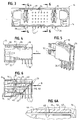
- an electrical connector generally designated 14, which includes a dielectric housing, generally designated 16, mounting a plurality of terminals which include two power terminals, generally designated 18, and twenty-four signal terminals, generally designated 20.
- the terminals are inserted into the rear of the housing, with the power terminals being inserted into terminal-receiving passages 22 (Fig. 2) and the signal terminals being inserted into terminal-receiving passages 24.
- Housing 16 of connector 14 includes a front mating face 26 (Fig. 1) and a rear terminal insertion face 28 (Fig. 2).
- the front face of the housing includes a receptacle 30 for receiving a plug portion of a complementary mating connector.
- contact portions 32 of power terminals 18 and contact pin portions 34 of signal terminals 20 project forwardly of the housing but are disposed within receptacle 30.
- each power terminal 18 includes an enlarged body portion 36 mounted within a respective one of the terminal-receiving passages 24 in the direction of arrow "A" (Fig. 4).
- Connector 14 is a header-type connector of a right-angular configuration for mounting on a printed circuit board. Therefore, each power terminal 18 includes a plurality of downwardly extending solder tails 38 for insertion into appropriate holes in the circuit board and for electrical connection, as by soldering, to circuit traces on the board and/or in the holes.
- each of the signal terminals 20 is a pin terminal having an L-shaped configuration defined by a horizontal leg 40 and a vertical leg 42.
- the terminals are inserted into the housing in the direction of arrow "B".
- the rear of the housing 16 is extended in a step fashion to correspond to the relative lengths of the horizontal legs 40 of the signal terminals 20.
- the horizontal legs terminate in contact pin portions 34 projecting into receptacle 30 of housing 16, as described above.
- Vertical legs 42 comprise solder tails for insertion into appropriate holes in the printed circuit board and for electrical connection to appropriate signal circuit traces on the board and/or in the holes.
- right-angled signal terminals 20 comprise pin terminals having contact pin portions 34 at one end and solder tails 42 at the opposite end.
- the terminals are polygonal in cross-section, preferably of a square configuration.
- the terminals are quite small and may be on the order of only 0.64 inch thick.
- terminal-receiving passages 24 also must be of a similar small size and configuration for guiding legs 40 of the terminals into the housing. As can be seen in Figure 6, passages 24 are considerably elongated and very narrow. Finally, Figure 6 shows that the terminals project through a narrow interior wall 44 of housing 16 and into receptacle 30.
- Figures 7-11 show housing 16 with the terminals removed to better show the configuration of the area of the housing about and including terminal-receiving passages 24 for signal terminals 20.
- Figure 7 shows that the passages 24 are closed on all four sides for short lengths thereof as the passages extend through interior wall 44 (also see Fig. 6) of the housing.
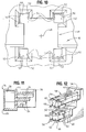
- Figures 8 and 9 show that the passages are arranged in six clusters, generally designated 48, with four passages 24 in each cluster. The four passages define an axis 49 generally centrally of the cluster of passages.
- each square terminal-receiving passages 24 is formed by four side walls 50 which meet at comers 52.
- the side walls provide guide surfaces for the inserted pin portions 34 of signal terminals 20.
- one of the comers and the adjacent side walls of each passage 24 is open, as at 54. It can be seen that the passages are open at the comers thereof nearest central axis 49. In essence, the major lengths of terminal-receiving passages 24 are in communication through openings 54, except for minor lengths of the passages which extend through narrow interior wall 44 of housing 16.
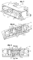
- Figure 12 shows a core pin tool, generally designated 56, which includes two core pins, generally designated 58, for forming eight terminal-receiving passages 24 for signal terminals 20.
- Tool 56 is effective for forming two vertically aligned clusters 48 of four passages in each cluster, as viewed in Figure 9.
- Each core pin 58 is effective to form one cluster 48 of four passages 24.
- each core pin 58 has a robust body 60 which is square in cross-section, with four square ribs 62 running along the length of the body at the four comers thereof.
- the ribs are dimensioned to form four passages 24 in one of the clusters 48 of the passages during molding of housing 16.
- body 60 forms an open area 64 within the cluster of four passages 24 and whereby the body can extend through openings 54 communicating with the passages.
- Ribs 62 of the core pin are integral with robust body 60.
- ribs 62 are sized to form a clearance zone 68 ( Figure 6A) aft of the interior wall 44 that eases the installation of the signal terminals 20 into the terminal-receiving passages 24.
- the clearance zone 68 provides a small clearance between the guiding legs 40 and the side walls 50, and the clearance zone 68 allows for guiding of the guide legs 40 of the signal terminals 20, especially toward the rear of the housing near the bend 70 of the signal terminal 20. The end result is better through position control of the horizontal legs 40 during installation of the signal terminals 20 in the housing 16.
- narrow square bosses 66 project lengthwise from the ends of ribs 60 for forming the short portions of the terminal-receiving passages which extend through narrow interior wall 44 of the housing. These bosses are only as long as the narrow thickness of the interior wall and, therefore, are not prone to breakage or deformation. Square bosses 66 are sized to allow for an interference fit of the forward end of the horizontal legs 40 of signal terminals 20 with that portion of the terminal receiving passage 24 at the interior wall 44 of the housing to allow for more rigid retention of the signal terminals 20 within the housing.
- each core pin 58 may comprise its own tool or there may be more than two core pins on a single tool, all depending upon the configuration of the molding die assembly used to mold plastic housing 16.
Landscapes
- Engineering & Computer Science (AREA)
- Manufacturing & Machinery (AREA)
- Connector Housings Or Holding Contact Members (AREA)
- Coupling Device And Connection With Printed Circuit (AREA)
Applications Claiming Priority (2)
| Application Number | Priority Date | Filing Date | Title |
|---|---|---|---|
| SG9905636A SG101926A1 (en) | 1999-11-12 | 1999-11-12 | Power connector |
| SG9905636 | 1999-11-12 |
Publications (2)
| Publication Number | Publication Date |
|---|---|
| EP1100155A2 true EP1100155A2 (de) | 2001-05-16 |
| EP1100155A3 EP1100155A3 (de) | 2002-07-17 |
Family
ID=20430464
Family Applications (1)
| Application Number | Title | Priority Date | Filing Date |
|---|---|---|---|
| EP00124478A Withdrawn EP1100155A3 (de) | 1999-11-12 | 2000-11-09 | Leistungssteckverbinder |
Country Status (6)
| Country | Link |
|---|---|
| US (1) | US6672884B1 (de) |
| EP (1) | EP1100155A3 (de) |
| JP (1) | JP3565161B2 (de) |
| CN (1) | CN1218441C (de) |
| SG (1) | SG101926A1 (de) |
| TW (1) | TW490089U (de) |
Cited By (1)
| Publication number | Priority date | Publication date | Assignee | Title |
|---|---|---|---|---|
| DE102008050161B4 (de) * | 2008-10-01 | 2017-08-03 | Bayerische Motoren Werke Aktiengesellschaft | Hybrider Steckverbinder |
Families Citing this family (43)
| Publication number | Priority date | Publication date | Assignee | Title |
|---|---|---|---|---|
| US20020098743A1 (en) * | 1998-04-17 | 2002-07-25 | Schell Mark S. | Power connector |
| FR2822598B1 (fr) * | 2001-03-21 | 2003-06-20 | Sagem | Connecteur de puissance pour circuit imprime |
| US6814590B2 (en) * | 2002-05-23 | 2004-11-09 | Fci Americas Technology, Inc. | Electrical power connector |
| US20040147169A1 (en) | 2003-01-28 | 2004-07-29 | Allison Jeffrey W. | Power connector with safety feature |
| US6780027B2 (en) * | 2003-01-28 | 2004-08-24 | Fci Americas Technology, Inc. | Power connector with vertical male AC power contacts |
| US6758685B1 (en) * | 2003-04-11 | 2004-07-06 | Compal Electronics, Inc. | Serial advanced technology attachment connector |
| US7049514B2 (en) * | 2003-09-30 | 2006-05-23 | Rockwell Automation Technologies, Inc. | Rail system for distributing power and data signals |
| US7458839B2 (en) * | 2006-02-21 | 2008-12-02 | Fci Americas Technology, Inc. | Electrical connectors having power contacts with alignment and/or restraining features |
| JP2007517373A (ja) | 2003-12-31 | 2007-06-28 | エフシーアイ | 電力接点およびこれを有するコネクタ |
| US7001189B1 (en) | 2004-11-04 | 2006-02-21 | Molex Incorporated | Board mounted power connector |
| US7384289B2 (en) | 2005-01-31 | 2008-06-10 | Fci Americas Technology, Inc. | Surface-mount connector |
| US7726982B2 (en) | 2006-06-15 | 2010-06-01 | Fci Americas Technology, Inc. | Electrical connectors with air-circulation features |
| JP2008146880A (ja) * | 2006-12-06 | 2008-06-26 | Denso Corp | コネクタ及び電子制御装置 |
| US7905731B2 (en) | 2007-05-21 | 2011-03-15 | Fci Americas Technology, Inc. | Electrical connector with stress-distribution features |
| KR101211462B1 (ko) * | 2007-09-28 | 2013-01-10 | 가부시끼가이샤 도시바 | 전원 커넥터 |
| US7762857B2 (en) * | 2007-10-01 | 2010-07-27 | Fci Americas Technology, Inc. | Power connectors with contact-retention features |
| US8062051B2 (en) * | 2008-07-29 | 2011-11-22 | Fci Americas Technology Llc | Electrical communication system having latching and strain relief features |
| USD664096S1 (en) | 2009-01-16 | 2012-07-24 | Fci Americas Technology Llc | Vertical electrical connector |
| USD608293S1 (en) | 2009-01-16 | 2010-01-19 | Fci Americas Technology, Inc. | Vertical electrical connector |
| USD606497S1 (en) | 2009-01-16 | 2009-12-22 | Fci Americas Technology, Inc. | Vertical electrical connector |
| USD610548S1 (en) | 2009-01-16 | 2010-02-23 | Fci Americas Technology, Inc. | Right-angle electrical connector |
| USD640637S1 (en) | 2009-01-16 | 2011-06-28 | Fci Americas Technology Llc | Vertical electrical connector |
| USD619099S1 (en) | 2009-01-30 | 2010-07-06 | Fci Americas Technology, Inc. | Electrical connector |
| US8323049B2 (en) * | 2009-01-30 | 2012-12-04 | Fci Americas Technology Llc | Electrical connector having power contacts |
| US8366485B2 (en) | 2009-03-19 | 2013-02-05 | Fci Americas Technology Llc | Electrical connector having ribbed ground plate |
| USD618180S1 (en) | 2009-04-03 | 2010-06-22 | Fci Americas Technology, Inc. | Asymmetrical electrical connector |
| USD618181S1 (en) | 2009-04-03 | 2010-06-22 | Fci Americas Technology, Inc. | Asymmetrical electrical connector |
| TWM420093U (en) * | 2011-08-26 | 2012-01-01 | Aces Electronic Co Ltd | Plug connector, jack connector and their assembly |
| EP2624034A1 (de) | 2012-01-31 | 2013-08-07 | Fci | Abbaubare optische Kupplungsvorrichtung |
| US9257778B2 (en) | 2012-04-13 | 2016-02-09 | Fci Americas Technology | High speed electrical connector |
| USD727268S1 (en) | 2012-04-13 | 2015-04-21 | Fci Americas Technology Llc | Vertical electrical connector |
| US8944831B2 (en) | 2012-04-13 | 2015-02-03 | Fci Americas Technology Llc | Electrical connector having ribbed ground plate with engagement members |
| USD727852S1 (en) | 2012-04-13 | 2015-04-28 | Fci Americas Technology Llc | Ground shield for a right angle electrical connector |
| USD718253S1 (en) | 2012-04-13 | 2014-11-25 | Fci Americas Technology Llc | Electrical cable connector |
| CN103545631B (zh) * | 2012-07-09 | 2016-03-09 | 凡甲电子(苏州)有限公司 | 电连接器 |
| US9543703B2 (en) | 2012-07-11 | 2017-01-10 | Fci Americas Technology Llc | Electrical connector with reduced stack height |
| USD751507S1 (en) | 2012-07-11 | 2016-03-15 | Fci Americas Technology Llc | Electrical connector |
| CN103811888A (zh) * | 2012-11-08 | 2014-05-21 | 凡甲电子(苏州)有限公司 | 电连接器 |
| USD745852S1 (en) | 2013-01-25 | 2015-12-22 | Fci Americas Technology Llc | Electrical connector |
| USD720698S1 (en) | 2013-03-15 | 2015-01-06 | Fci Americas Technology Llc | Electrical cable connector |
| CN104103954B (zh) * | 2013-04-08 | 2018-01-02 | 泰科电子公司 | 具有整体的导引元件的电连接器 |
| USD931225S1 (en) * | 2019-10-04 | 2021-09-21 | Molex, Llc | Connector |
| USD924168S1 (en) * | 2019-11-15 | 2021-07-06 | Molex, Llc | Connector |
Citations (5)
| Publication number | Priority date | Publication date | Assignee | Title |
|---|---|---|---|---|
| DE3634795A1 (de) * | 1986-10-11 | 1988-04-14 | Telefonbau & Normalzeit Gmbh | Federleiste zur befestigung auf einer leiterplatte |
| US5173063A (en) * | 1990-02-20 | 1992-12-22 | Amp Incorporated | Receptacle connector having protected power contacts |
| DE4332996A1 (de) * | 1993-09-28 | 1995-03-30 | Siemens Ag | Steckverbinder zur Kontaktierung einer Leiterplatte |
| EP0730324A2 (de) * | 1995-01-05 | 1996-09-04 | Thomas & Betts Corporation | Verbesserter abgeschirmter kompakter Datensteckverbinder |
| EP0860911A2 (de) * | 1997-02-21 | 1998-08-26 | Berg Electronics Manufacturing B.V. | Leiterplattenverbinder für Einpressmontage |
Family Cites Families (19)
| Publication number | Priority date | Publication date | Assignee | Title |
|---|---|---|---|---|
| US3864000A (en) * | 1973-06-07 | 1975-02-04 | Amp Inc | Mating contact connector housing assembly |
| US4425015A (en) | 1980-05-29 | 1984-01-10 | Texas Instruments Incorporated | Attachable, circuit-terminating, circuit board edge member |
| US4697864A (en) | 1986-06-19 | 1987-10-06 | Amp Incorporated | Printed circuit board receptacle for sealed connector |
| US4767342A (en) * | 1987-12-07 | 1988-08-30 | Hirose Electric Co., Ltd. | Electrical connector for printed circuit board |
| US5104329A (en) * | 1990-09-21 | 1992-04-14 | Amp Incorporated | Electrical connector assembly |
| US5037334A (en) | 1990-11-30 | 1991-08-06 | Amp Corporated | Connector with equal lateral force contact spacer plate |
| JP2904424B2 (ja) | 1991-03-25 | 1999-06-14 | 日本エー・エム・ピー株式会社 | 基板用コネクタ及びそれに用いるタインプレート |
| US5102353A (en) * | 1991-06-06 | 1992-04-07 | Molex Incorporated | Electrical connectors |
| US5295843A (en) * | 1993-01-19 | 1994-03-22 | The Whitaker Corporation | Electrical connector for power and signal contacts |
| US5820417A (en) * | 1993-03-08 | 1998-10-13 | Yazaki Corporation | Connector housing |
| NL9300971A (nl) | 1993-06-04 | 1995-01-02 | Framatome Connectors Belgium | Connectorsamenstel voor printkaarten. |
| US5378175A (en) * | 1993-12-22 | 1995-01-03 | Molex Incorporated | Electrical connector for mounting on a printed circuit board |
| US5490787A (en) | 1994-08-29 | 1996-02-13 | The Whitaker Corporation | Electrical connector with integral supporting structure |
| FR2727258B1 (fr) | 1994-11-21 | 1996-12-20 | Cinch Connecteurs Sa | Connecteur electrique |
| US5667411A (en) | 1995-09-08 | 1997-09-16 | Molex Incorporated | Electrical connector having terminal alignment means |
| US5702257A (en) | 1996-02-29 | 1997-12-30 | The Whitaker Corporation | Electrical connector and terminal therefor |
| JP3511431B2 (ja) * | 1996-04-01 | 2004-03-29 | カルソニックカンセイ株式会社 | 端子係止具付コネクタ |
| JP2910682B2 (ja) | 1996-07-30 | 1999-06-23 | 日本電気株式会社 | 高速伝送用コネクタ |
| US6217347B1 (en) * | 1999-10-01 | 2001-04-17 | Berg Technology, Inc. | Electrical connector having multiple arrays of contacts with co-linear mounting points |
-
1999
- 1999-11-12 SG SG9905636A patent/SG101926A1/en unknown
-
2000
- 2000-11-03 US US09/709,786 patent/US6672884B1/en not_active Expired - Lifetime
- 2000-11-09 EP EP00124478A patent/EP1100155A3/de not_active Withdrawn
- 2000-11-09 JP JP2000381088A patent/JP3565161B2/ja not_active Expired - Fee Related
- 2000-11-10 TW TW089219548U patent/TW490089U/zh not_active IP Right Cessation
- 2000-11-11 CN CN001355325A patent/CN1218441C/zh not_active Expired - Fee Related
Patent Citations (5)
| Publication number | Priority date | Publication date | Assignee | Title |
|---|---|---|---|---|
| DE3634795A1 (de) * | 1986-10-11 | 1988-04-14 | Telefonbau & Normalzeit Gmbh | Federleiste zur befestigung auf einer leiterplatte |
| US5173063A (en) * | 1990-02-20 | 1992-12-22 | Amp Incorporated | Receptacle connector having protected power contacts |
| DE4332996A1 (de) * | 1993-09-28 | 1995-03-30 | Siemens Ag | Steckverbinder zur Kontaktierung einer Leiterplatte |
| EP0730324A2 (de) * | 1995-01-05 | 1996-09-04 | Thomas & Betts Corporation | Verbesserter abgeschirmter kompakter Datensteckverbinder |
| EP0860911A2 (de) * | 1997-02-21 | 1998-08-26 | Berg Electronics Manufacturing B.V. | Leiterplattenverbinder für Einpressmontage |
Cited By (1)
| Publication number | Priority date | Publication date | Assignee | Title |
|---|---|---|---|---|
| DE102008050161B4 (de) * | 2008-10-01 | 2017-08-03 | Bayerische Motoren Werke Aktiengesellschaft | Hybrider Steckverbinder |
Also Published As
| Publication number | Publication date |
|---|---|
| EP1100155A3 (de) | 2002-07-17 |
| CN1218441C (zh) | 2005-09-07 |
| JP3565161B2 (ja) | 2004-09-15 |
| SG101926A1 (en) | 2004-02-27 |
| TW490089U (en) | 2002-06-01 |
| US6672884B1 (en) | 2004-01-06 |
| CN1299163A (zh) | 2001-06-13 |
| JP2001185301A (ja) | 2001-07-06 |
Similar Documents
| Publication | Publication Date | Title |
|---|---|---|
| US6672884B1 (en) | Power connector | |
| EP0795929B1 (de) | Elektrische Verbinderanordnung mit verbessertem Haltemittel | |
| US6071152A (en) | Electrical connector with inserted terminals | |
| KR100241845B1 (ko) | 개선된 보유 수단을 갖는 단자를 구비한 전기 커넥터 | |
| US6343951B1 (en) | Electrical connector | |
| JP4019156B2 (ja) | 極低背基板実装型モジュラージャック | |
| US5344327A (en) | Electrical connectors | |
| US6231355B1 (en) | Matched impedance connector having retention device on a grounding plane | |
| EP0846350B1 (de) | Herstellungsverfahren oberflachenmontierbarer verbinder | |
| US7402081B2 (en) | Electrical connector with improved metallic shell | |
| US4891017A (en) | Socket connector with pin aligning housing | |
| EP0635905A1 (de) | Elektrischer Erdungsverbinder | |
| US20050095913A1 (en) | Shielded board-mounted electrical connector | |
| US20050112952A1 (en) | Power jack connector | |
| US6648657B1 (en) | Electrical connector having ground buses | |
| US6227905B1 (en) | Receptacle electrical connector assembly | |
| US7309241B2 (en) | Pick and place electrical connector | |
| US20060128228A1 (en) | Modular jack connector | |
| US7112105B2 (en) | Cable assembly having power contacts | |
| JP2001230004A (ja) | 電気コネクタ | |
| US6152781A (en) | Electrical connector | |
| CA2242287C (en) | Connector | |
| US20030153202A1 (en) | Card connector | |
| US6780063B2 (en) | Wire connected modular jack and assembling method | |
| US5011435A (en) | Modular jack |
Legal Events
| Date | Code | Title | Description |
|---|---|---|---|
| PUAI | Public reference made under article 153(3) epc to a published international application that has entered the european phase |
Free format text: ORIGINAL CODE: 0009012 |
|
| AK | Designated contracting states |
Kind code of ref document: A2 Designated state(s): AT BE CH CY DE DK ES FI FR GB GR IE IT LI LU MC NL PT SE TR |
|
| AX | Request for extension of the european patent |
Free format text: AL;LT;LV;MK;RO;SI |
|
| PUAL | Search report despatched |
Free format text: ORIGINAL CODE: 0009013 |
|
| AK | Designated contracting states |
Kind code of ref document: A3 Designated state(s): AT BE CH CY DE DK ES FI FR GB GR IE IT LI LU MC NL PT SE TR |
|
| AX | Request for extension of the european patent |
Free format text: AL;LT;LV;MK;RO;SI |
|
| RIC1 | Information provided on ipc code assigned before grant |
Free format text: 7H 01R 12/20 A, 7H 01R 43/18 B |
|
| AKX | Designation fees paid |
Designated state(s): DE FR GB IT |
|
| STAA | Information on the status of an ep patent application or granted ep patent |
Free format text: STATUS: THE APPLICATION IS DEEMED TO BE WITHDRAWN |
|
| 18D | Application deemed to be withdrawn |
Effective date: 20030118 |