EP0635905A1 - Elektrischer Erdungsverbinder - Google Patents
Elektrischer Erdungsverbinder Download PDFInfo
- Publication number
- EP0635905A1 EP0635905A1 EP94110509A EP94110509A EP0635905A1 EP 0635905 A1 EP0635905 A1 EP 0635905A1 EP 94110509 A EP94110509 A EP 94110509A EP 94110509 A EP94110509 A EP 94110509A EP 0635905 A1 EP0635905 A1 EP 0635905A1
- Authority
- EP
- European Patent Office
- Prior art keywords
- terminal
- electrical connector
- ground plate
- ground
- terminals
- Prior art date
- Legal status (The legal status is an assumption and is not a legal conclusion. Google has not performed a legal analysis and makes no representation as to the accuracy of the status listed.)
- Granted
Links
- 230000013011 mating Effects 0.000 claims abstract description 31
- 230000000295 complement effect Effects 0.000 claims description 14
- 239000000463 material Substances 0.000 claims description 3
- 239000002991 molded plastic Substances 0.000 claims description 3
- 230000008054 signal transmission Effects 0.000 description 22
- 230000005540 biological transmission Effects 0.000 description 16
- 239000004020 conductor Substances 0.000 description 8
- 239000003989 dielectric material Substances 0.000 description 3
- 239000002131 composite material Substances 0.000 description 2
- 238000010276 construction Methods 0.000 description 2
- 238000003780 insertion Methods 0.000 description 2
- 230000037431 insertion Effects 0.000 description 2
- 230000002093 peripheral effect Effects 0.000 description 2
- 210000002105 tongue Anatomy 0.000 description 2
- 230000008878 coupling Effects 0.000 description 1
- 238000010168 coupling process Methods 0.000 description 1
- 238000005859 coupling reaction Methods 0.000 description 1
- 239000002184 metal Substances 0.000 description 1
- 239000007769 metal material Substances 0.000 description 1
- 238000005192 partition Methods 0.000 description 1
- 239000004033 plastic Substances 0.000 description 1
- 229910000679 solder Inorganic materials 0.000 description 1
- 239000007787 solid Substances 0.000 description 1
Images


Classifications
-
- H—ELECTRICITY
- H01—ELECTRIC ELEMENTS
- H01R—ELECTRICALLY-CONDUCTIVE CONNECTIONS; STRUCTURAL ASSOCIATIONS OF A PLURALITY OF MUTUALLY-INSULATED ELECTRICAL CONNECTING ELEMENTS; COUPLING DEVICES; CURRENT COLLECTORS
- H01R12/00—Structural associations of a plurality of mutually-insulated electrical connecting elements, specially adapted for printed circuits, e.g. printed circuit boards [PCB], flat or ribbon cables, or like generally planar structures, e.g. terminal strips, terminal blocks; Coupling devices specially adapted for printed circuits, flat or ribbon cables, or like generally planar structures; Terminals specially adapted for contact with, or insertion into, printed circuits, flat or ribbon cables, or like generally planar structures
-
- H—ELECTRICITY
- H01—ELECTRIC ELEMENTS
- H01R—ELECTRICALLY-CONDUCTIVE CONNECTIONS; STRUCTURAL ASSOCIATIONS OF A PLURALITY OF MUTUALLY-INSULATED ELECTRICAL CONNECTING ELEMENTS; COUPLING DEVICES; CURRENT COLLECTORS
- H01R13/00—Details of coupling devices of the kinds covered by groups H01R12/70 or H01R24/00 - H01R33/00
- H01R13/648—Protective earth or shield arrangements on coupling devices, e.g. anti-static shielding
-
- H—ELECTRICITY
- H01—ELECTRIC ELEMENTS
- H01R—ELECTRICALLY-CONDUCTIVE CONNECTIONS; STRUCTURAL ASSOCIATIONS OF A PLURALITY OF MUTUALLY-INSULATED ELECTRICAL CONNECTING ELEMENTS; COUPLING DEVICES; CURRENT COLLECTORS
- H01R12/00—Structural associations of a plurality of mutually-insulated electrical connecting elements, specially adapted for printed circuits, e.g. printed circuit boards [PCB], flat or ribbon cables, or like generally planar structures, e.g. terminal strips, terminal blocks; Coupling devices specially adapted for printed circuits, flat or ribbon cables, or like generally planar structures; Terminals specially adapted for contact with, or insertion into, printed circuits, flat or ribbon cables, or like generally planar structures
- H01R12/70—Coupling devices
- H01R12/71—Coupling devices for rigid printing circuits or like structures
- H01R12/712—Coupling devices for rigid printing circuits or like structures co-operating with the surface of the printed circuit or with a coupling device exclusively provided on the surface of the printed circuit
-
- H—ELECTRICITY
- H01—ELECTRIC ELEMENTS
- H01R—ELECTRICALLY-CONDUCTIVE CONNECTIONS; STRUCTURAL ASSOCIATIONS OF A PLURALITY OF MUTUALLY-INSULATED ELECTRICAL CONNECTING ELEMENTS; COUPLING DEVICES; CURRENT COLLECTORS
- H01R13/00—Details of coupling devices of the kinds covered by groups H01R12/70 or H01R24/00 - H01R33/00
- H01R13/648—Protective earth or shield arrangements on coupling devices, e.g. anti-static shielding
- H01R13/658—High frequency shielding arrangements, e.g. against EMI [Electro-Magnetic Interference] or EMP [Electro-Magnetic Pulse]
- H01R13/6581—Shield structure
- H01R13/6585—Shielding material individually surrounding or interposed between mutually spaced contacts
-
- H—ELECTRICITY
- H01—ELECTRIC ELEMENTS
- H01R—ELECTRICALLY-CONDUCTIVE CONNECTIONS; STRUCTURAL ASSOCIATIONS OF A PLURALITY OF MUTUALLY-INSULATED ELECTRICAL CONNECTING ELEMENTS; COUPLING DEVICES; CURRENT COLLECTORS
- H01R12/00—Structural associations of a plurality of mutually-insulated electrical connecting elements, specially adapted for printed circuits, e.g. printed circuit boards [PCB], flat or ribbon cables, or like generally planar structures, e.g. terminal strips, terminal blocks; Coupling devices specially adapted for printed circuits, flat or ribbon cables, or like generally planar structures; Terminals specially adapted for contact with, or insertion into, printed circuits, flat or ribbon cables, or like generally planar structures
- H01R12/70—Coupling devices
- H01R12/7005—Guiding, mounting, polarizing or locking means; Extractors
- H01R12/7011—Locking or fixing a connector to a PCB
- H01R12/7017—Snap means
- H01R12/7023—Snap means integral with the coupling device
-
- H—ELECTRICITY
- H01—ELECTRIC ELEMENTS
- H01R—ELECTRICALLY-CONDUCTIVE CONNECTIONS; STRUCTURAL ASSOCIATIONS OF A PLURALITY OF MUTUALLY-INSULATED ELECTRICAL CONNECTING ELEMENTS; COUPLING DEVICES; CURRENT COLLECTORS
- H01R12/00—Structural associations of a plurality of mutually-insulated electrical connecting elements, specially adapted for printed circuits, e.g. printed circuit boards [PCB], flat or ribbon cables, or like generally planar structures, e.g. terminal strips, terminal blocks; Coupling devices specially adapted for printed circuits, flat or ribbon cables, or like generally planar structures; Terminals specially adapted for contact with, or insertion into, printed circuits, flat or ribbon cables, or like generally planar structures
- H01R12/70—Coupling devices
- H01R12/7005—Guiding, mounting, polarizing or locking means; Extractors
- H01R12/7011—Locking or fixing a connector to a PCB
- H01R12/7017—Snap means
- H01R12/7029—Snap means not integral with the coupling device
Definitions
- This invention generally relates to the art of electrical connectors and, particularly, to an electrical connector system having grounded interconnectable terminal modules.
- Electrical connectors are used to interconnect signal transmission lines to printed circuit boards, other electronic devices or to other complementary connectors.
- the transmission lines transmit signals through a plurality of conductors which, preferably, are physically separated and electromagnetically isolated along their length.
- the predominant system embodies a plurality of plug-in type connectors in mating engagement with receptacle connectors on the computer, its main printed circuit board or other electronic devices.
- the transmission lines typically include coaxial electrical cables, either in round or flat form, and round cables are presently being used predominantly in relatively high frequency applications between various system components.
- cables usually utilize twisted pairs of conductors to achieve the necessary characteristics, particularly impedance control and cross talk control.
- Coaxial cables are used in singular conductor configurations in high frequency applications, such as to a high-speed video monitor. Most often, the lower speed data transmission lines are separated from the high speed signal transmission lines. Consequently, different electrical connectors are often used for the lower speed data transmission lines than for the high speed signal lines. This adds to the problem of requiring multiple connectors in ever-increasing miniaturized and high density applications.
- the present invention is directed to further improvements in such connectors by providing novel grounding terminal modules having interconnectable ground plates, the modules being components of complementary mating electrical connectors.
- An object, therefore, of the invention is to provide a new and improved electrical connector system for interconnecting signal transmission lines in electronic devices, such as computers or the like.
- an electrical connector system in the exemplary embodiment of the invention, includes a shielded connector for mating with a complementary connector along a mating axis.
- the shielded connector has a dielectric housing.
- An outer conductive shield member generally surrounds a mating portion of the dielectric housing.
- the invention contemplates providing an opening in the housing, and a grounding terminal module is adapted to be inserted into the opening.
- the module includes a ground member clamped between a pair of dielectric terminal blocks. At least one terminal is mounted in each terminal block.
- the terminal blocks are fabricated of molded plastic material with the respective terminals thereof being insert molded therein.
- the ground member is a generally planar ground plate separating the respective terminals mounted in the terminal blocks and providing primary capacitive coupling between each terminal and the ground member.
- the complementary connector also include a generally planar ground plate for engaging the ground plate of the grounding terminal module of the shielded connector.
- One of the ground plates of the module and the complementary connector includes a slot for receiving the other ground plate and thereby define an interengaging cross-shaped grounding structure therebetween.
- Each dielectric terminal block mounts a pair of terminals in a spaced disposition such that one terminal is located in each of four quadrants defined by the cross-shaped grounding structure of the interengaging ground plates.
- electrical connector 10 for terminating both the conductors of slower data transmission lines and the conductors of high speed or high frequency transmission lines. More particularly, electrical connector 10 includes a dielectric housing, generally designated 12, a conductive shield, generally designated 14, data transmission terminal modules, generally designated 16 (Fig. 2), a high speed signal transmission terminal module, generally designated 18, and a tail aligning device, generally designated 20.
- the overall configuration of dielectric housing 12 and conductive shield 14 define a generally rectangular electrical connector.
- Dielectric housing 12 includes a forwardly directed, generally rectangular mating portion 22 projecting forwardly from an enlarged, transversely outwardly projecting flange portion 24 as best seen in Figure 2.
- a pair of triangulated side wings 26 project rearwardly from opposite sides of flange portion 24.
- Mating portion 22 defines a mating face 28 as best seen in Figure 1.
- the housing is unitarily molded of dielectric material such as plastic or the like, and a pair of ramped latch bosses 30 are molded integral with and project outwardly from both the top and bottom of flange portion 24 as seen in Figure 2, for latching interengagement with conductive shield 14 as described hereinafter.
- the rear of dielectric housing 12 includes a receptacle area 34 for receiving data transmission terminal modules 16, and an opening 36 for receiving high speed signal transmission terminal module 18.
- Grooves 38 are formed on the inside of side wings 26 for slidingly receiving tail aligning device 20.
- the front face 28 of mating portion 22 of the dielectric housing has a first array of passages 40 for receiving a plurality of lower speed data contacts or terminals from the complementary mating connector, and a second array of passages 42 for receiving a plurality of high speed signal contacts or terminals of the complementary connector.
- Conductive shield 14 has a forwardly projecting, generally rectangularly shaped shroud portion 44 for surrounding mating portion 22 of dielectric housing 12, along with a peripheral face plate portion 46 for substantially covering the front surface of flange portion 24 of the housing.
- the shield has a pair of rearwardly projecting flanges 48, each flange having a pair of latch apertures 50 formed therein.
- a pair of legs 52 project rearwardly from opposite sides of peripheral face plate portion 46, each leg terminating in a bifurcated boardlock 54 which is insertable into an appropriate mounting hole in a printed circuit board and for interconnection with a ground circuit on the board or in the hole.
- the conductive shield is fabricated of stamped and formed sheet metal and is assembled to dielectric housing 12 as shown in Figure 1, whereupon ramped latch bosses 30 snap into latching engagement within latch apertures 50 of the shield.
- High speed signal transmission terminal modules 16 have elongated dielectric blocks 56 within which a plurality of data transmission terminals are insert molded.
- the data transmission terminals include contact or terminal portions 58 (Fig. 2) which project into the first array of passages 40 (Fig. 1).
- the data transmission terminals have tail portions 60 projecting from the rear of blocks 56 and angled downwardly with composite bonds resulting in a right-angle to a mating axis of the connector perpendicular to mating face 28.
- high speed signal transmission terminal module 18 includes a modular block construction, generally designated 62, for mounting a plurality of high speed signal terminals each having a forwardly projecting contact or terminal portion 64 (Fig. 2) projecting into a respective one of the second array of passages 42 (Fig. 1) in mating face 28 of the dielectric housing.
- the high speed signal transmission terminals have tail portions 66 projecting rearwardly and downwardly with composite bonds resulting in a right-angle to the mating axis of the connector.
- high speed signal transmission terminal module 18 includes a ground plate 68 located between two pairs of terminal tails 66 of the signal transmission terminal module.
- the ground plate itself, has tails 70 projecting downwardly therefrom.
- tail aligning device 20 is assembled to terminal modules 16 and 18 by insertion of the tails of the terminals into apertures 72,74 as described above, and as indicated by arrow "A" in Figure 2. This subassembly then is assembled to dielectric housing 12 in the direction of arrow "B” by inserting data transmission terminal modules 16 into receptacle area 34 and high speed signal transmission terminal module 18 into opening 36, as tail aligning device 20 slides within grooves 38 of the dielectric housing.
- the invention herein is directed primarily to the construction of high speed signal transmission terminal module 18, as well as to an electrical connector system wherein the terminal module is groundingly interconnected with a terminal module of a second or complementary electrical connector, described hereinafter.
- the mounting block structure 62 of terminal module 18 includes a pair of identical terminal blocks 62a, one terminal block being shown in Figure 3, and a pair of the terminal blocks being shown in Figure 4 in a mirror-imaged orientation.
- a pair of terminals, generally designated 80 in Figure 3 are insert molded in each terminal block 62a so that contact or terminal portions 64 project forwardly out of the front side of the terminal blocks and tails 66 project rearwardly out of the rear side of the blocks as seen in Figure 4.
- the terminal blocks have slots 82 for edge-wise clamping ground plate 68 therebetween, as described hereinafter.
- each terminal block 62a includes a ramped latch boss 84 for snapping behind upper and lower ramped latch bosses 86 (Fig. 2) when terminal module 18 is inserted or assembled into opening 36.
- FIGs 2, 5 and 6 show how terminal blocks 62a clamp ground plate 68 therebetween.
- the ground plate is located between the two terminals of each terminal block 62a as best seen in Figure 5.
- Figure 6 shows that each terminal block 62a includes an interior cavity 88 for receiving a barbed locking tongue 90 integral with the ground plate which may be stamped from sheet metal material.
- the terminal blocks can be considered to clamp the ground plate when the module is inserted into opening 36 in connector housing 12, in initial assembled condition, the terminal blocks actually are locked onto the ground plate by means of locking tongues 90 within cavities 88 by an interference fit therebetween.
- ground plate 68 includes a slot 92 which has a chamfered mouth 92a at the front of terminal module 18.
- the slot opens in a mating direction of the connector.
- ground plate 68 is located in a vertical groove 94 in mating portion 22 of dielectric housing 12, and mouth 92a opens in mating face 28 of the housing.
- a horizontal slot or groove 96 also is formed in the mating portion of the dielectric housing, intersecting groove 94 and ground plate 68 in a cross-shaped configuration. It also should be noted that passages 42 are located individually in each of four quadrants defined by grooves 94 and 96.
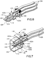
- the invention contemplates a novel electrical connector system wherein connector 10 (Figs. 1 and 2) is mateable with a second or complementary connector in a unique manner for providing an interengaging grounding connection with high speed signal transmission terminal module 18. More particularly, Figures 7-9 show the high speed signal transmission terminal end of a second or complementary electrical connector, generally designated 100. The entire connector is not shown, because the inventive concept is directed to the grounding interconnection with terminal module 18.
- a second high speed signal transmission terminal module includes a pair of inner terminal blocks 102a and 102b which clamp a second ground plate 104 therebetween.
- Each terminal block 102a and 102b mount a pair of terminals 106 which are terminated to respective conductor wires 108.
- the terminals are mounted within the terminal blocks so that contact or terminal portions 110 project forwardly from the terminal blocks, with two contact portions from each terminal block being located on each opposite side of ground plate 104, as best seen in Figure 8.
- Inner terminal blocks 102a and 102b are snapped within a pair of outer terminal blocks 102c and 102d by means of ramped latch bosses 111 on the inner terminal blocks which latch behind shoulders 111a of the outer terminal blocks.
- Connector 100 also is a shielded electrical connector and includes a shield member 112 having a forwardly projecting shroud portion 114 which is adapted to surround and engage shroud portion 44 of shield 14 of connector 10 as best seen in Figure 1.
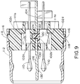
- Shield 112 has a plurality of apertures 116 for snap-latch engagement with ramped latch bosses 118 molded integrally with outer terminal blocks 102c and 102d as best seen in Figures 7 and 9.
- ground plate 104 The means for clamping ground plate 104 between terminal blocks 102a and 102b is best shown in Figure 9.
- the ground plate has a hole 120 through which a post 122 from terminal block 102b projects.
- the post extends through the hole in the ground plate and into a recess 124 in terminal block 102a.
- post 122 could be press-fit within recess 124 for preliminary assembly of the terminal blocks and the ground plate, once this subassembly is inserted into shield 112 as shown in Figure 9, the terminal blocks are effective to clamp the ground plate therebetween.
- ground plate 104 has a spring finger 126 stamped out of the center thereof.
- the spring finger is cantilevered about a point 128.
- the spring finger has a pair of dimples 130 formed therein, the dimples being most clearly shown in Figure 9.
- ground plates 104 and 68 When fully mated, ground plates 104 and 68 define a cross-shaped grounding structure therebetween, with one pair of the mating terminal contact portions 64 and 110 being located in each quadrant defined by the cross-shaped grounding structure of the interengaging ground plates.
- Spring finger 126 and detents 130 of ground plate 104 enter slot 92 of ground plate 68 and establish a solid interconnection between the two ground plates.
Landscapes
- Details Of Connecting Devices For Male And Female Coupling (AREA)
- Coupling Device And Connection With Printed Circuit (AREA)
Applications Claiming Priority (2)
| Application Number | Priority Date | Filing Date | Title |
|---|---|---|---|
| US08/096,117 US5304069A (en) | 1993-07-22 | 1993-07-22 | Grounding electrical connectors |
| US96117 | 1993-07-22 |
Publications (2)
| Publication Number | Publication Date |
|---|---|
| EP0635905A1 true EP0635905A1 (de) | 1995-01-25 |
| EP0635905B1 EP0635905B1 (de) | 1998-09-16 |
Family
ID=22255466
Family Applications (1)
| Application Number | Title | Priority Date | Filing Date |
|---|---|---|---|
| EP94110509A Expired - Lifetime EP0635905B1 (de) | 1993-07-22 | 1994-07-06 | Elektrischer Erdungsverbinder |
Country Status (6)
| Country | Link |
|---|---|
| US (2) | US5304069A (de) |
| EP (1) | EP0635905B1 (de) |
| JP (1) | JP3006992U (de) |
| KR (1) | KR0118212Y1 (de) |
| DE (1) | DE69413334T2 (de) |
| SG (1) | SG45324A1 (de) |
Cited By (1)
| Publication number | Priority date | Publication date | Assignee | Title |
|---|---|---|---|---|
| EP0793309A2 (de) * | 1996-03-01 | 1997-09-03 | Molex Incorporated | System für Anschluss der Abschirmung eines Hochfrequenzkabels |
Families Citing this family (67)
| Publication number | Priority date | Publication date | Assignee | Title |
|---|---|---|---|---|
| US5546281A (en) | 1995-01-13 | 1996-08-13 | Methode Electronics, Inc. | Removable optoelectronic transceiver module with potting box |
| US5717533A (en) | 1995-01-13 | 1998-02-10 | Methode Electronics Inc. | Removable optoelectronic module |
| US6220878B1 (en) | 1995-10-04 | 2001-04-24 | Methode Electronics, Inc. | Optoelectronic module with grounding means |
| US5591050A (en) * | 1995-02-09 | 1997-01-07 | Molex Incorporated | Shielded electrical connector |
| US5645435A (en) * | 1995-08-02 | 1997-07-08 | The Whitaker Corporation | Electrical connector |
| US5580283A (en) * | 1995-09-08 | 1996-12-03 | Molex Incorporated | Electrical connector having terminal modules |
| US5667411A (en) * | 1995-09-08 | 1997-09-16 | Molex Incorporated | Electrical connector having terminal alignment means |
| US5558542A (en) * | 1995-09-08 | 1996-09-24 | Molex Incorporated | Electrical connector with improved terminal-receiving passage means |
| US5716236A (en) * | 1996-03-01 | 1998-02-10 | Molex Incorporated | System for terminating the shield of a high speed cable |
| SG55278A1 (en) * | 1996-03-01 | 1998-12-21 | Molex Inc | System for terminating the shield of a high speed cable |
| TW326584B (en) * | 1996-03-01 | 1998-02-11 | Molex Inc | System for terminating the shield of high speed cables(7) |
| US5725387A (en) * | 1996-03-01 | 1998-03-10 | Molex Incorporated | System for terminating the shield of a high speed cable |
| US5785555A (en) * | 1996-03-01 | 1998-07-28 | Molex Incorporated | System for terminating the shield of a high speed cable |
| US5961348A (en) * | 1996-03-01 | 1999-10-05 | Molex Incorporated | System for terminating the shield of a high speed cable |
| US5718607A (en) * | 1996-03-01 | 1998-02-17 | Molex Incorporated | System for terminating the shield of a high speed cable |
| DE19621614C1 (de) * | 1996-05-30 | 1997-12-18 | Itt Cannon Gmbh | Steckverbinder |
| US5813871A (en) * | 1996-07-31 | 1998-09-29 | The Whitaker Corporation | High frequency electrical connector |
| US5876248A (en) * | 1997-01-14 | 1999-03-02 | Molex Incorporated | Matable electrical connectors having signal and power terminals |
| US5863222A (en) * | 1997-06-03 | 1999-01-26 | The Whitaker Corporation | Shielded electrical connector |
| JP3278050B2 (ja) * | 1997-06-16 | 2002-04-30 | タイコエレクトロニクスアンプ株式会社 | シールド型コネクタ |
| US6293811B1 (en) * | 1997-10-09 | 2001-09-25 | The Whitaker Corporation | Connector and heating element assembly |
| DE19810561A1 (de) * | 1998-03-11 | 1999-09-16 | Siemens Ag | Hybrider Datenstecker |
| US6179627B1 (en) | 1998-04-22 | 2001-01-30 | Stratos Lightwave, Inc. | High speed interface converter module |
| US6203333B1 (en) | 1998-04-22 | 2001-03-20 | Stratos Lightwave, Inc. | High speed interface converter module |
| US6065998A (en) * | 1998-12-29 | 2000-05-23 | Molex Incorporated | Electrical connector for coaxial cable |
| US6164995A (en) * | 1999-03-09 | 2000-12-26 | Molex Incorporated | Impedance tuning in electrical switching connector |
| US6142804A (en) * | 1999-03-09 | 2000-11-07 | Molex Incorporated | Electrical switching connector |
| US6116926A (en) * | 1999-04-21 | 2000-09-12 | Berg Technology, Inc. | Connector for electrical isolation in a condensed area |
| US6123554A (en) * | 1999-05-28 | 2000-09-26 | Berg Technology, Inc. | Connector cover with board stiffener |
| US6565387B2 (en) * | 1999-06-30 | 2003-05-20 | Teradyne, Inc. | Modular electrical connector and connector system |
| US6220873B1 (en) | 1999-08-10 | 2001-04-24 | Stratos Lightwave, Inc. | Modified contact traces for interface converter |
| US6186828B1 (en) | 1999-08-30 | 2001-02-13 | Molex Incorporated | Electrical connector including coaxial cable management system |
| US6200163B1 (en) * | 1999-08-30 | 2001-03-13 | Molex Incorporated | Electrical connector including means for terminating the shield of a high speed cable |
| DE10084896T1 (de) | 1999-09-24 | 2002-10-31 | Litton Systems Inc | Elektrisches Verbindungssystem hoher Dichte mit verbesserten Eigenschaften zur Erdung und Verringerung von Übersprechen |
| JP3502984B2 (ja) | 1999-12-01 | 2004-03-02 | モレックス インコーポレーテッド | 電気コネクタ装置 |
| US6312268B1 (en) * | 1999-12-13 | 2001-11-06 | Tekcon Electronics Corp. | Electric connector with a positioning terminal |
| US6364710B1 (en) | 2000-03-29 | 2002-04-02 | Berg Technology, Inc. | Electrical connector with grounding system |
| JP2001313130A (ja) * | 2000-04-28 | 2001-11-09 | Japan Aviation Electronics Industry Ltd | コンタクトをグループ化したコネクタ |
| JP3779867B2 (ja) * | 2000-08-31 | 2006-05-31 | アルプス電気株式会社 | 接地端子及びそれを用いたicカード用コネクタ |
| JP3801448B2 (ja) * | 2001-01-31 | 2006-07-26 | タイコエレクトロニクスアンプ株式会社 | シールドコネクタ組立体 |
| US6607308B2 (en) | 2001-02-12 | 2003-08-19 | E20 Communications, Inc. | Fiber-optic modules with shielded housing/covers having mixed finger types |
| US6659655B2 (en) | 2001-02-12 | 2003-12-09 | E20 Communications, Inc. | Fiber-optic modules with housing/shielding |
| JP2002280121A (ja) * | 2001-03-19 | 2002-09-27 | Jst Mfg Co Ltd | 電気コネクタ、および伝送路 |
| JP2002280124A (ja) * | 2001-03-19 | 2002-09-27 | Jst Mfg Co Ltd | 電気コネクタ |
| US6790096B2 (en) * | 2001-12-28 | 2004-09-14 | Hon Hai Precision Ind. Co., Ltd. | Cable assembly having arrangement for organizing cable |
| US7404724B1 (en) * | 2004-04-02 | 2008-07-29 | Robert Dennis Miller | Connector with ESD inhibiting shell |
| TWM279084U (en) * | 2005-04-15 | 2005-10-21 | Top Yang Technology Entpr Co | Electrical connector with a metal casing |
| US7086866B1 (en) * | 2005-10-27 | 2006-08-08 | Molex Incorporated | Circuit board mounted electrical connector |
| TWM297565U (en) * | 2006-01-23 | 2006-09-11 | Amphenol Taiwan Corp | Micro socket connector |
| KR100751809B1 (ko) * | 2006-05-17 | 2007-08-24 | 주식회사 대우일렉트로닉스 | 전자파 차단 커넥터 |
| US8007308B2 (en) * | 2007-10-17 | 2011-08-30 | 3M Innovative Properties Company | Electrical connector assembly |
| CN101828308B (zh) * | 2007-10-19 | 2013-06-12 | 3M创新有限公司 | 电连接器组件 |
| TWM357748U (en) * | 2007-10-29 | 2009-05-21 | Hon Hai Prec Ind Co Ltd | Electrical connector |
| DE102009019626B3 (de) * | 2009-04-30 | 2011-03-03 | Tyco Electronics Amp Gmbh | Elektrischer Verbinder mit Impedanzkorrekturelement und Verfahren zu seiner Herstellung |
| US8742814B2 (en) | 2009-07-15 | 2014-06-03 | Yehuda Binder | Sequentially operated modules |
| US8602833B2 (en) | 2009-08-06 | 2013-12-10 | May Patents Ltd. | Puzzle with conductive path |
| US7748999B1 (en) * | 2009-08-26 | 2010-07-06 | Cheng Uei Precision Industry Co., Ltd. | Electrical Connector |
| US11330714B2 (en) | 2011-08-26 | 2022-05-10 | Sphero, Inc. | Modular electronic building systems with magnetic interconnections and methods of using the same |
| US9019718B2 (en) | 2011-08-26 | 2015-04-28 | Littlebits Electronics Inc. | Modular electronic building systems with magnetic interconnections and methods of using the same |
| US9597607B2 (en) | 2011-08-26 | 2017-03-21 | Littlebits Electronics Inc. | Modular electronic building systems with magnetic interconnections and methods of using the same |
| US8556657B1 (en) * | 2012-05-25 | 2013-10-15 | Tyco Electronics Corporation | Electrical connector having split footprint |
| TWI577094B (zh) * | 2014-08-28 | 2017-04-01 | 連展科技股份有限公司 | 插頭電連接器 |
| TWM497873U (zh) * | 2014-12-02 | 2015-03-21 | Simula Technology Inc | 以一體式舌板固定金屬間隔板之訊號連接器 |
| US9385479B1 (en) * | 2015-07-27 | 2016-07-05 | Tyco Electronics Corporation | Overmolded connector sub-assembly |
| US10096930B2 (en) * | 2016-02-24 | 2018-10-09 | Hosiden Corporation | Connector |
| CN207925721U (zh) * | 2018-01-30 | 2018-09-28 | 富誉电子科技(淮安)有限公司 | 电源连接器 |
| US11616844B2 (en) | 2019-03-14 | 2023-03-28 | Sphero, Inc. | Modular electronic and digital building systems and methods of using the same |
Citations (3)
| Publication number | Priority date | Publication date | Assignee | Title |
|---|---|---|---|---|
| US4968261A (en) * | 1989-02-15 | 1990-11-06 | Daiichi Denshi Kogyo Kabushiki Kaisha | Electrical connector |
| US5102353A (en) * | 1991-06-06 | 1992-04-07 | Molex Incorporated | Electrical connectors |
| US5174770A (en) * | 1990-11-15 | 1992-12-29 | Amp Incorporated | Multicontact connector for signal transmission |
Family Cites Families (2)
| Publication number | Priority date | Publication date | Assignee | Title |
|---|---|---|---|---|
| US4846711A (en) * | 1988-08-09 | 1989-07-11 | Amp Incorporated | Coaxial connector in a housing block |
| GB8928777D0 (en) * | 1989-12-20 | 1990-02-28 | Amp Holland | Sheilded backplane connector |
-
1993
- 1993-07-22 US US08/096,117 patent/US5304069A/en not_active Ceased
-
1994
- 1994-07-06 DE DE69413334T patent/DE69413334T2/de not_active Expired - Fee Related
- 1994-07-06 EP EP94110509A patent/EP0635905B1/de not_active Expired - Lifetime
- 1994-07-06 SG SG1996003522A patent/SG45324A1/en unknown
- 1994-07-21 JP JP1994010029U patent/JP3006992U/ja not_active Expired - Lifetime
- 1994-07-21 KR KR2019940018077U patent/KR0118212Y1/ko not_active IP Right Cessation
-
1996
- 1996-04-19 US US08/636,730 patent/USRE35896E/en not_active Expired - Lifetime
Patent Citations (3)
| Publication number | Priority date | Publication date | Assignee | Title |
|---|---|---|---|---|
| US4968261A (en) * | 1989-02-15 | 1990-11-06 | Daiichi Denshi Kogyo Kabushiki Kaisha | Electrical connector |
| US5174770A (en) * | 1990-11-15 | 1992-12-29 | Amp Incorporated | Multicontact connector for signal transmission |
| US5102353A (en) * | 1991-06-06 | 1992-04-07 | Molex Incorporated | Electrical connectors |
Cited By (2)
| Publication number | Priority date | Publication date | Assignee | Title |
|---|---|---|---|---|
| EP0793309A2 (de) * | 1996-03-01 | 1997-09-03 | Molex Incorporated | System für Anschluss der Abschirmung eines Hochfrequenzkabels |
| EP0793309A3 (de) * | 1996-03-01 | 1998-08-12 | Molex Incorporated | System für Anschluss der Abschirmung eines Hochfrequenzkabels |
Also Published As
| Publication number | Publication date |
|---|---|
| KR0118212Y1 (ko) | 1998-06-01 |
| DE69413334D1 (de) | 1998-10-22 |
| DE69413334T2 (de) | 1999-05-06 |
| EP0635905B1 (de) | 1998-09-16 |
| SG45324A1 (en) | 1998-01-16 |
| USRE35896E (en) | 1998-09-15 |
| KR950004859U (ko) | 1995-02-18 |
| JP3006992U (ja) | 1995-01-31 |
| US5304069A (en) | 1994-04-19 |
Similar Documents
| Publication | Publication Date | Title |
|---|---|---|
| US5304069A (en) | Grounding electrical connectors | |
| US5344327A (en) | Electrical connectors | |
| US5417590A (en) | Plug and socket electrical connector system | |
| US6431914B1 (en) | Grounding scheme for a high speed backplane connector system | |
| US6835092B2 (en) | Stacked electrical connector assembly with enhanced grounding arrangement | |
| CA2069379C (en) | Electrical connector having contact retention means | |
| EP0795929B1 (de) | Elektrische Verbinderanordnung mit verbessertem Haltemittel | |
| CA1188381A (en) | Shielded electrical connector | |
| EP0517180B1 (de) | Elektrische Verbinder | |
| US5174770A (en) | Multicontact connector for signal transmission | |
| EP0590544B1 (de) | Abgeschirmter elektrischer Stecker | |
| US5387114A (en) | Electrical connector with means for altering circuit characteristics | |
| EP1719210B1 (de) | Verbindervorrichtung | |
| US7824187B1 (en) | High density connector | |
| US20050277334A1 (en) | Electrical connector with shielding member | |
| US20020048992A1 (en) | Vertically stacked usb connector | |
| US7435106B2 (en) | Cable connector assembly with internal printed circuit board | |
| EP0624928B1 (de) | Abgeschirmte elektrische Verbinderanordnung | |
| US6159040A (en) | Insulator for retaining contacts of connector assembly and method for making the same | |
| US20010016453A1 (en) | Shielded connector with integral latching and ground structure | |
| US6749445B1 (en) | Electrical connector with spacer | |
| US6083041A (en) | Electrical connector mounting assembly | |
| EP0510264B1 (de) | Verbinderanordnung für Koaxialkabel | |
| EP0540310A1 (de) | Elektrischer Verbinder mit aussenseitig befestigten Erdpotentialschichten |
Legal Events
| Date | Code | Title | Description |
|---|---|---|---|
| PUAI | Public reference made under article 153(3) epc to a published international application that has entered the european phase |
Free format text: ORIGINAL CODE: 0009012 |
|
| AK | Designated contracting states |
Kind code of ref document: A1 Designated state(s): DE FR GB IT NL |
|
| 17P | Request for examination filed |
Effective date: 19950531 |
|
| 17Q | First examination report despatched |
Effective date: 19951121 |
|
| GRAG | Despatch of communication of intention to grant |
Free format text: ORIGINAL CODE: EPIDOS AGRA |
|
| GRAG | Despatch of communication of intention to grant |
Free format text: ORIGINAL CODE: EPIDOS AGRA |
|
| GRAH | Despatch of communication of intention to grant a patent |
Free format text: ORIGINAL CODE: EPIDOS IGRA |
|
| GRAH | Despatch of communication of intention to grant a patent |
Free format text: ORIGINAL CODE: EPIDOS IGRA |
|
| ITF | It: translation for a ep patent filed | ||
| GRAA | (expected) grant |
Free format text: ORIGINAL CODE: 0009210 |
|
| AK | Designated contracting states |
Kind code of ref document: B1 Designated state(s): DE FR GB IT NL |
|
| REF | Corresponds to: |
Ref document number: 69413334 Country of ref document: DE Date of ref document: 19981022 |
|
| ET | Fr: translation filed | ||
| PLBE | No opposition filed within time limit |
Free format text: ORIGINAL CODE: 0009261 |
|
| STAA | Information on the status of an ep patent application or granted ep patent |
Free format text: STATUS: NO OPPOSITION FILED WITHIN TIME LIMIT |
|
| 26N | No opposition filed | ||
| PGFP | Annual fee paid to national office [announced via postgrant information from national office to epo] |
Ref country code: GB Payment date: 20010614 Year of fee payment: 8 |
|
| PGFP | Annual fee paid to national office [announced via postgrant information from national office to epo] |
Ref country code: NL Payment date: 20010618 Year of fee payment: 8 |
|
| REG | Reference to a national code |
Ref country code: GB Ref legal event code: IF02 |
|
| PG25 | Lapsed in a contracting state [announced via postgrant information from national office to epo] |
Ref country code: GB Free format text: LAPSE BECAUSE OF NON-PAYMENT OF DUE FEES Effective date: 20020706 |
|
| PG25 | Lapsed in a contracting state [announced via postgrant information from national office to epo] |
Ref country code: NL Free format text: LAPSE BECAUSE OF NON-PAYMENT OF DUE FEES Effective date: 20030201 |
|
| GBPC | Gb: european patent ceased through non-payment of renewal fee |
Effective date: 20020706 |
|
| NLV4 | Nl: lapsed or anulled due to non-payment of the annual fee |
Effective date: 20030201 |
|
| PG25 | Lapsed in a contracting state [announced via postgrant information from national office to epo] |
Ref country code: IT Free format text: LAPSE BECAUSE OF NON-PAYMENT OF DUE FEES;WARNING: LAPSES OF ITALIAN PATENTS WITH EFFECTIVE DATE BEFORE 2007 MAY HAVE OCCURRED AT ANY TIME BEFORE 2007. THE CORRECT EFFECTIVE DATE MAY BE DIFFERENT FROM THE ONE RECORDED. Effective date: 20050706 |
|
| PGFP | Annual fee paid to national office [announced via postgrant information from national office to epo] |
Ref country code: FR Payment date: 20050706 Year of fee payment: 12 |
|
| PGFP | Annual fee paid to national office [announced via postgrant information from national office to epo] |
Ref country code: DE Payment date: 20050729 Year of fee payment: 12 |
|
| PG25 | Lapsed in a contracting state [announced via postgrant information from national office to epo] |
Ref country code: DE Free format text: LAPSE BECAUSE OF NON-PAYMENT OF DUE FEES Effective date: 20070201 |
|
| REG | Reference to a national code |
Ref country code: FR Ref legal event code: ST Effective date: 20070330 |
|
| PG25 | Lapsed in a contracting state [announced via postgrant information from national office to epo] |
Ref country code: FR Free format text: LAPSE BECAUSE OF NON-PAYMENT OF DUE FEES Effective date: 20060731 |