EP1099629A1 - Indicateur de défaut de fermeture, notamment pour des capots de nacelle d'un moteur d'avion - Google Patents
Indicateur de défaut de fermeture, notamment pour des capots de nacelle d'un moteur d'avion Download PDFInfo
- Publication number
- EP1099629A1 EP1099629A1 EP20000403073 EP00403073A EP1099629A1 EP 1099629 A1 EP1099629 A1 EP 1099629A1 EP 20000403073 EP20000403073 EP 20000403073 EP 00403073 A EP00403073 A EP 00403073A EP 1099629 A1 EP1099629 A1 EP 1099629A1
- Authority
- EP
- European Patent Office
- Prior art keywords
- stop
- covers
- indicator according
- elements
- indicator
- Prior art date
- Legal status (The legal status is an assumption and is not a legal conclusion. Google has not performed a legal analysis and makes no representation as to the accuracy of the status listed.)
- Granted
Links
Images



Classifications
-
- B—PERFORMING OPERATIONS; TRANSPORTING
- B64—AIRCRAFT; AVIATION; COSMONAUTICS
- B64D—EQUIPMENT FOR FITTING IN OR TO AIRCRAFT; FLIGHT SUITS; PARACHUTES; ARRANGEMENT OR MOUNTING OF POWER PLANTS OR PROPULSION TRANSMISSIONS IN AIRCRAFT
- B64D29/00—Power-plant nacelles, fairings or cowlings
-
- E—FIXED CONSTRUCTIONS
- E05—LOCKS; KEYS; WINDOW OR DOOR FITTINGS; SAFES
- E05B—LOCKS; ACCESSORIES THEREFOR; HANDCUFFS
- E05B41/00—Locks with visible indication as to whether the lock is locked or unlocked
-
- Y—GENERAL TAGGING OF NEW TECHNOLOGICAL DEVELOPMENTS; GENERAL TAGGING OF CROSS-SECTIONAL TECHNOLOGIES SPANNING OVER SEVERAL SECTIONS OF THE IPC; TECHNICAL SUBJECTS COVERED BY FORMER USPC CROSS-REFERENCE ART COLLECTIONS [XRACs] AND DIGESTS
- Y10—TECHNICAL SUBJECTS COVERED BY FORMER USPC
- Y10T—TECHNICAL SUBJECTS COVERED BY FORMER US CLASSIFICATION
- Y10T292/00—Closure fasteners
- Y10T292/08—Bolts
- Y10T292/0911—Hooked end
- Y10T292/0913—Sliding and swinging
- Y10T292/0914—Operating means
- Y10T292/0917—Lever
Definitions
- the invention relates to a fault indicator for closing locking means interposed between two elements able to occupy, one in relation to the other, an open position and a closed position.
- Such an indicator can in particular be used on an aircraft engine, to immediately inform the ground staff of a failure to close the means of interlocking which are interposed between covers of the nacelle of said engine.
- the aircraft engine nacelles are usually fitted with covers, the opening of which allows access, when the aircraft is on the ground, to different equipment, systems, etc., to ensure maintenance.
- the covers are closed and have a shape such that ensure the aerodynamic continuity of the engine in its together.
- the nacelle of a turbofan is generally equipped at least one pair of covers, respectively right and left, placed around the blower of the engine.
- Each cover presents in section approximately the shape of a C in a plane transverse perpendicular to the longitudinal axis of the engine.
- a hinge allows to articulate the edge top of each of the covers on the upper part of the engine. Thanks to this arrangement, it is possible access the various engine equipment, especially to carry out maintenance, by reporting the covers.
- the lower edges of the covers are fitted with locking mechanisms designed to lock the covers in their closed position when these mechanisms are activated.
- These mechanisms generally have a male part and a female part mounted on the lower edges respective covers, so as to be able to cooperate between them when the covers are closed.
- the hood locking can only be done after the operator has manually raised the arm in order to place it on a receptacle provided for this purpose.
- a linked pin opposite hood enters arm to hold it in its retracted position.
- a spring automatically brings the arm in its projecting position, visible from the outside.
- the hood locking mechanism is located under the engine, in a place very close to the ground and therefore difficult access.
- the arm added to the mechanism lock according to document EP-A-0 596 070 then constitutes a protruding part which is added other blunt parts of the engine that could injuring the operator.
- the subject of the invention is precisely a closing fault indicator ensuring effective visualization of such a defect, while overcoming the disadvantages of the indicator described in document EP-A-0 596 070, that is to say in particular in not complicating manufacture or implementation of the locking mechanism.
- this result is obtained by means of a closing fault indicator locking means interposed between two elements capable of occupying one with respect to the other, an open position and a closed position, said indicator being characterized in that it includes retractable stop means capable of holding automatically the two items pushed aside one of the other, when switching from the open position to the closed position.
- the indicator is arranged to in such a way that the locking means cannot be closed only when the stop means are retracted.
- this arrangement is, from preferably, such that the stop means cannot be retracted only by a voluntary action of an operator.
- This voluntary action can in particular be carried out at using an appropriate tool.
- the retractable stop means comprise at least one stop member capable of being moved between a stable state in which one, mobile, said elements automatically comes into contact with the stop member when it moves from its position open to its closed position, and an unstable state, in which the displacement of the movable element up to its closed position is possible.
- elastic means then request the stop member towards its state stable.
- the stop member can in particular be mounted so as to be able to pivot around a fixed axis, to move from its stable state to its unstable state, and Conversely.
- the retractable stop means include two stop members each of which is assigned to one of the elements.
- the two stop members can then be mounted so that they can pivot around the same axis fixed.
- the two elements are nacelle covers of a airplane engine.
- the edges of the covers suitable for be retracted when the covers are in position closed and to be visible when kept separated by the retractable stop means, include means capable of increasing the visibility, such as fluorescent paint or bright color.
- the nacelle of a turbofan engine is usually bounded inward, at the right blower (not shown) by a housing blower 10 and, outwards, by two covers 12 and 14, respectively right and left.
- Each of the covers 12 and 14 have substantially the shape of a C or of a semicircle, in cross section according to a plane perpendicular to the longitudinal axis of the engine.
- Each of the covers 12 and 14 is articulated, by its upper edge, on a mast 16 by which the engine hangs under the wing of an airplane. More precisely, the upper edge of each of the covers 12 and 14 is connected to the mast 16, to the upper part of the motor, by a respective hinge 18, 20 whose axis is substantially parallel to the longitudinal axis of the engine. As shown schematically in dashed lines in FIG. 1 for the right cover 12, this arrangement makes it possible to raise each of the covers 12 and 14 in order to access different equipment (not shown) of the engine, traditionally installed in the annular space 22 delimited inside the nacelle between the fan casing 10 and the covers.
- covers 12 and 14 When covers 12 and 14 occupy their closed position, illustrated in solid lines in the figure 1, they are normally locked by means of lock (not shown) such as multiple toggle mechanisms, or the like, comparable to mechanism described in document US-A-4,531,769, interposed between the lower edges of the covers.
- lock such as multiple toggle mechanisms, or the like, comparable to mechanism described in document US-A-4,531,769, interposed between the lower edges of the covers.
- the faces 30 and 32 of the pins 26 and 28, turned towards each other when the covers 12 and 14 are in the closed position, are flat.
- these faces 30 and 32 are substantially parallel to a plane vertical median passing through the longitudinal axis of the engine, when the covers are in the closed position.
- the opposite faces of the pins 26 and 28, designated by the references 34 and 36 on the Figures 2 to 4, have sections substantially in quadrant shape, the center of which is located approximately at the intersection of the flat face 30, 32 corresponding with the inner face of the cover 12, 14 bearing the lug under consideration.
- FIGs 2 to 4 we also have shown a front guide 38, fixed at the bottom of the rear face of the air inlet 39 of the nacelle.
- This front guide 38 is connected, by bolts 40, to a rear guide (not shown), so as to delimit between the two guides on the right and left in which the pins are normally received 26 and 28 when the covers 12 and 14 are in position closed ( Figure 4).
- the closing fault indicator 24 is mounted directly on the front guide 38 and takes advantage of the presence of pins 26 and 28 near the edge bottom of each of the covers 12 and 14.
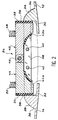
- Closing fault indicator 24 in this case comprises two abutment members 42 and 44, respectively right and left, constituting retractable stop means capable of holding automatically covers 12 and 14 apart one of the other, when these move from their position open to their closed position. More precise, the two stop members 42 and 44 are mounted pivotally on the front guide 38, by via a common axis 46 placed above the guide 38, in the median vertical plane of the motor passing through the longitudinal axis thereof, and oriented parallel to said axis.
- Each of the stop members 42 and 44 includes a lower part 42a, 44a likely to come place in the gap formed between the front guide 38 and the rear guide (not shown), in which are received the pins 26 and 28 when the covers are closed.
- the stop members 42 and 44 then occupy a low position, as illustrated in Figures 2 and 4. This low position constitutes a position stable, towards which they tend to return under the action of gravity and under the action of means elastic bands such as springs 48 and 50 shown schematically in Figures 2 and 4.
- stop members 42 and 44 When the stop members 42 and 44 occupy this low position they extend respectively to the right and to the left in one direction substantially horizontal, on either side of their common pivot axis 46.
- This indication can be further improved by placing on the edges of the covers which then protrude the air intake means to increase their visibility, such as fluorescent paint or bright color or any other coating or treatment likely to catch the eye of even an observer attentive.
- the stop members 42, 44 can be made of any material sufficient resistant to not wear too quickly on contact pins 26 and 28.
- this material can in particular be steel stainless.
- Protective parts 56 and 58 by rubber example, can be reported on sides 52 and 54, or possibly on the faces of stop 30 and 32 of the pins 26 and 28, in order to improve still wear resistance.
- each of the stop members 42 and 44 has a recessed portion 60, 62, with an arc section of circle in which automatically fits the corresponding pin 26, 28, under the effect of a new downward tilting of the stop members 42 and 44 controlled by springs 48 and 50, when the covers 12 and 14 are closed and locked.
- Protection blocks 64, 66 for example in rubber can also be reported in recessed parts 60 and 62 or on surfaces 34 and 36 lugs, in order to avoid excessively rapid wear of the different rooms.
- the covers 12 and 14 are opened by usual way, by unlocking the mechanisms locking, then spreading the bottom edges of the covers, by pivoting them around the hinges 18 and 20 ( Figure 1).
- the cooperation of sides 34 and 36 of pins 26 and 28 with the recessed parts 60 and 62 of the stop members 42 and 44 then has the effect of making pivot these upwards, against return springs 48 and 50.
- the pins 26 and 28 fall back into their stable position illustrated in Figures 2 and 4. They then prevent automatically closing the covers completely without external intervention, as explained previously.
- the indicator according to the invention can be mounted on an existing engine, as on a new engine, without the need to modify the covers, or add parts.
- the usual front guide is simply replaced by the guide 38 carrying the stop members 42, 44.
- the embodiment described does not is just one example and can suffer many modifications, without departing from the scope of the invention.
- the invention is particularly suitable in the case of aircraft engine nacelle covers, it can be used in many others applications, when there is a risk of forgetting for locking a door in the closed position.
- the items to be locked may include a fixed element and a movable element.
- the stop members can pivot around two separate axes or be replaced by one or two bodies capable of sliding vertically between a high, unstable position, and a low position, stable.
- the recall means constituted in the example described by helical springs of compression, can be replaced by any organs technically equivalent such as springs to blades.
Landscapes
- Engineering & Computer Science (AREA)
- Aviation & Aerospace Engineering (AREA)
- Superstructure Of Vehicle (AREA)
- Structures Of Non-Positive Displacement Pumps (AREA)
- Mechanisms For Operating Contacts (AREA)
- Body Structure For Vehicles (AREA)
Abstract
Description
- la figure 1 est une vue en coupe transversale schématique d'une nacelle de moteur d'avion, au droit d'une paire de capots équipant celle-ci, et en regardant vers l'avant du moteur, un indicateur de défaut de fermeture conforme à l'invention étant interposé entre les extrémités basses des capots ;
- la figure 2 est une vue en coupe à plus grande échelle illustrant un mode de réalisation préféré d'un indicateur de défaut de fermeture conforme à l'invention, dans l'état qu'il occupe lorsque les capots sont en position basse de fermeture mais que les moyens de verrouillage n'ont pas été actionnés ;
- la figure 3 est une vue comparable à la figure 2, illustrant l'escamotage des moyens de butée équipant l'indicateur, pour la mise la mise en oeuvre des moyens de verrouillage ; et
- la figure 4 est une vue en coupe comparable aux figures 2 et 3, illustrant l'indicateur lorsque les moyens de verrouillage ont été actionnés.
Claims (10)
- Indicateur de défaut de fermeture de moyens de verrouillage interposés entre deux éléments (12,14) aptes à occuper, l'un par rapport à l'autre, une position ouverte et une position fermée, ledit indicateur étant caractérisé en ce qu'il comprend des moyens de butée escamotables (42,44) aptes à maintenir automatiquement les deux éléments (12,14) écartés l'un de l'autre, lors d'un passage de la position ouverte vers la position fermée.
- Indicateur selon la revendication 1, dans lequel les moyens de verrouillage ne peuvent être fermés que lorsque les moyens de butée (42,44) sont escamotés.
- Indicateur selon l'une quelconque des revendications 1 et 2, dans lequel les moyens de butée (42,44) ne peuvent être escamotés que par une action volontaire d'un opérateur.
- Indicateur selon l'une quelconque des revendications précédentes, dans lequel les moyens de butée escamotables comprennent au moins un organe de butée (42,44) apte à être déplacé entre un état stable dans lequel l'un, mobile, desdits éléments (12,14) vient automatiquement en appui contre ledit organe de butée lorsqu'il se déplace de sa position ouverte vers sa position fermée, et un état instable, dans lequel le déplacement dudit élément mobile (12,14) jusqu'à sa position fermée est possible.
- Indicateur selon la revendication 4, dans lequel des moyens élastiques (48,50) sollicitent ledit organe de butée (42,44) vers son état stable.
- Indicateur selon l'une quelconque des revendications 4 et 5, dans lequel ledit organe de butée (42,44) est apte à pivoter autour d'un axe fixe (46), pour se déplacer de son état stable dans son état instable, et inversement.
- Indicateur selon l'une quelconque des revendications 4 à 6, dans lequel lesdits éléments (12,14) sont tous deux mobiles et les moyens de butée escamotables comprennent deux organes de butée (42,44) dont chacun est affecté à l'un desdits éléments (12,14).
- Indicateur selon les revendications 6 et 7 combinées, dans lequel les deux organes de butée (42,44) sont aptes à pivoter autour d'un même axe fixe (46).
- Indicateur selon l'une quelconque des revendications précédentes, dans lequel les deux éléments sont des capots (12,14) de nacelle d'un moteur d'avion.
- Indicateur selon la revendication 9, dans lequel des rebords des capots (12,14), aptes à être escamotés lorsque les capots sont en position fermée et à être apparents lorsqu'ils sont maintenus écartés par les moyens de butée escamotables (42,44), comportent des moyens aptes à en accroítre la visibilité.
Applications Claiming Priority (2)
| Application Number | Priority Date | Filing Date | Title |
|---|---|---|---|
| FR9914121A FR2800707B1 (fr) | 1999-11-10 | 1999-11-10 | Indicateur de defaut de fermeture, notamment pour des capots de nacelle d'un moteur d'avion |
| FR9914121 | 1999-11-10 |
Publications (2)
| Publication Number | Publication Date |
|---|---|
| EP1099629A1 true EP1099629A1 (fr) | 2001-05-16 |
| EP1099629B1 EP1099629B1 (fr) | 2005-07-13 |
Family
ID=9551956
Family Applications (1)
| Application Number | Title | Priority Date | Filing Date |
|---|---|---|---|
| EP20000403073 Expired - Lifetime EP1099629B1 (fr) | 1999-11-10 | 2000-11-07 | Capots de nacelle d'un moteur d'avion comprenant un indicateur de défaut de fermeture |
Country Status (6)
| Country | Link |
|---|---|
| US (1) | US6666408B1 (fr) |
| EP (1) | EP1099629B1 (fr) |
| CA (1) | CA2325870C (fr) |
| DE (1) | DE60021244T2 (fr) |
| ES (1) | ES2244398T3 (fr) |
| FR (1) | FR2800707B1 (fr) |
Cited By (10)
| Publication number | Priority date | Publication date | Assignee | Title |
|---|---|---|---|---|
| EP1314839A1 (fr) * | 2001-11-27 | 2003-05-28 | Airbus France | Dispositif indicateur de défaut de fermeture pour nacelle de moteur d'avion |
| FR2835870A1 (fr) | 2002-02-14 | 2003-08-15 | Airbus France | Systeme de fermeture interpose entre deux elements |
| WO2012037988A1 (fr) * | 2010-09-24 | 2012-03-29 | Short Brothers Plc | Nacelle dotée de portes de capot articulées permettant d'accéder au moteur |
| WO2015015111A1 (fr) * | 2013-08-02 | 2015-02-05 | Aircelle | Ensemble propulsif pour aéronef |
| FR3019526A1 (fr) * | 2014-04-07 | 2015-10-09 | Airbus Operations Sas | Nacelle d'aeronef comportant un systeme d'ecartement destine a maintenir les deux capots ecartes |
| CN105460224A (zh) * | 2014-09-29 | 2016-04-06 | 空中客车防务及航天股份有限公司 | 用于飞机发动机短舱的整流罩的对齐和安全装置 |
| US20180273210A1 (en) * | 2017-03-22 | 2018-09-27 | Safran Aero Boosters Sa | Turbomachine Cowling with Screen |
| WO2019121863A1 (fr) * | 2017-12-22 | 2019-06-27 | Lufthansa Technik Ag | Dispositif de verrouillage destiné à des trappes sur des avions |
| EP3772445A1 (fr) * | 2019-08-09 | 2021-02-10 | SpeedInnov | Trappe de véhicule avec contraste visuel |
| US12227976B2 (en) * | 2022-01-12 | 2025-02-18 | Delta Electronics, Inc. | Locking mechanism and electronic device |
Families Citing this family (13)
| Publication number | Priority date | Publication date | Assignee | Title |
|---|---|---|---|---|
| ES2281227B1 (es) * | 2004-12-31 | 2008-09-16 | Airbus España, S.L. | Un mecanismo de accionamiento de una trampa, particularmente para un tren de aterrizaje de un avion. |
| US7375533B2 (en) * | 2005-06-15 | 2008-05-20 | Gale Robert D | Continuity tester adaptors |
| FR2907759B1 (fr) * | 2006-10-31 | 2008-12-12 | Aircelle Sa | Nacelle pour turboreacteur a ouverture laterale |
| FR2920144B1 (fr) * | 2007-08-20 | 2010-01-08 | Aircelle Sa | Nacelle equipee d'un dispositif de detection de l'etat de verrouillage d'un dispositif de verrouillage |
| FR2920171B1 (fr) * | 2007-08-20 | 2017-01-13 | Aircelle Sa | Dispositif de verrouillage concu pour etre dispose dans une zone de jonction d'une nacelle |
| ES2359305B1 (es) | 2008-07-09 | 2012-03-23 | Eads Construcciones Aeronauticas, S.A. | Dispositivo para una unidad de propulsión de una aeronave. |
| US9783315B2 (en) * | 2012-02-24 | 2017-10-10 | Rohr, Inc. | Nacelle with longitudinal translating cowling and rotatable sleeves |
| FR3015435B1 (fr) * | 2013-12-20 | 2016-02-05 | Aircelle Sa | Nacelle de turboreacteur comprenant un verrou de demi-parties arriere securise |
| FR3016157B1 (fr) * | 2014-01-07 | 2018-03-02 | Airbus Operations (S.A.S) | Nacelle d'aeronef comprenant un dispositif visuel d'alerte de defaut de verrouillage des capots. |
| DE102015226546A1 (de) | 2015-12-22 | 2017-06-22 | Rolls-Royce Deutschland Ltd & Co Kg | Triebwerksverkleidung |
| US10239628B2 (en) * | 2016-09-15 | 2019-03-26 | Rohr, Inc. | Set of latches with identical components for nacelle doors |
| US10822102B2 (en) * | 2017-06-16 | 2020-11-03 | Rohr, Inc. | Adjustable length beam between cowl hinges |
| ES2943140T3 (es) * | 2019-02-05 | 2023-06-09 | Airbus Defence & Space Sau | Sistema de aviso de estado abierto de una cubierta de ventilador de dos partes |
Citations (6)
| Publication number | Priority date | Publication date | Assignee | Title |
|---|---|---|---|---|
| US4150802A (en) * | 1977-05-31 | 1979-04-24 | The Boeing Company | Aircraft engine installation |
| US4531769A (en) | 1982-08-25 | 1985-07-30 | The Boeing Company | Hook latch for an engine cowling |
| US4613099A (en) * | 1982-02-05 | 1986-09-23 | The Boeing Company | Latch signal and cowling structure |
| US4679750A (en) * | 1984-06-20 | 1987-07-14 | The Boeing Company | Latch system |
| GB2267122A (en) * | 1992-05-22 | 1993-11-24 | Short Brothers Plc | Closure fault indicator |
| EP0596070A1 (fr) | 1992-05-22 | 1994-05-11 | Short Brothers Plc | Indicateur de defaillance de fermeture. |
Family Cites Families (4)
| Publication number | Priority date | Publication date | Assignee | Title |
|---|---|---|---|---|
| SE461473B (sv) * | 1987-06-11 | 1990-02-19 | Aake Kjellstroem | Anordning vid doerr foer att foerhindra klaemskador |
| FR2765917B1 (fr) * | 1997-07-10 | 1999-08-20 | Hispano Suiza Sa | Inverseur de poussee a visualisation de verrouillage |
| US6279971B1 (en) * | 1999-10-05 | 2001-08-28 | Hartwell Corporation | Latch with sensor |
| US6325428B1 (en) * | 1999-11-10 | 2001-12-04 | Hartwell Corporation | Latch assembly including sensor |
-
1999
- 1999-11-10 FR FR9914121A patent/FR2800707B1/fr not_active Expired - Lifetime
-
2000
- 2000-10-13 US US09/689,830 patent/US6666408B1/en not_active Expired - Lifetime
- 2000-11-07 DE DE2000621244 patent/DE60021244T2/de not_active Expired - Lifetime
- 2000-11-07 EP EP20000403073 patent/EP1099629B1/fr not_active Expired - Lifetime
- 2000-11-07 ES ES00403073T patent/ES2244398T3/es not_active Expired - Lifetime
- 2000-11-08 CA CA002325870A patent/CA2325870C/fr not_active Expired - Lifetime
Patent Citations (6)
| Publication number | Priority date | Publication date | Assignee | Title |
|---|---|---|---|---|
| US4150802A (en) * | 1977-05-31 | 1979-04-24 | The Boeing Company | Aircraft engine installation |
| US4613099A (en) * | 1982-02-05 | 1986-09-23 | The Boeing Company | Latch signal and cowling structure |
| US4531769A (en) | 1982-08-25 | 1985-07-30 | The Boeing Company | Hook latch for an engine cowling |
| US4679750A (en) * | 1984-06-20 | 1987-07-14 | The Boeing Company | Latch system |
| GB2267122A (en) * | 1992-05-22 | 1993-11-24 | Short Brothers Plc | Closure fault indicator |
| EP0596070A1 (fr) | 1992-05-22 | 1994-05-11 | Short Brothers Plc | Indicateur de defaillance de fermeture. |
Cited By (18)
| Publication number | Priority date | Publication date | Assignee | Title |
|---|---|---|---|---|
| FR2832752A1 (fr) | 2001-11-27 | 2003-05-30 | Airbus France | Dispositif indicateur de defaut de fermeture d'au moins un mecanisme de verrouillage interpose entre deux elements |
| US6824175B2 (en) | 2001-11-27 | 2004-11-30 | Airbus France | Device for indicating incorrect closure of locking means located between two fan cowlings of an aircraft engine nacelle |
| EP1314839A1 (fr) * | 2001-11-27 | 2003-05-28 | Airbus France | Dispositif indicateur de défaut de fermeture pour nacelle de moteur d'avion |
| FR2835870A1 (fr) | 2002-02-14 | 2003-08-15 | Airbus France | Systeme de fermeture interpose entre deux elements |
| WO2012037988A1 (fr) * | 2010-09-24 | 2012-03-29 | Short Brothers Plc | Nacelle dotée de portes de capot articulées permettant d'accéder au moteur |
| US9650917B2 (en) | 2010-09-24 | 2017-05-16 | Short Brothers Plc | Nacelle with hinged cowl doors enabling access to the engine |
| WO2015015111A1 (fr) * | 2013-08-02 | 2015-02-05 | Aircelle | Ensemble propulsif pour aéronef |
| FR3009279A1 (fr) * | 2013-08-02 | 2015-02-06 | Aircelle Sa | Ensemble propulsif pour aeronef |
| US9849995B2 (en) | 2014-04-07 | 2017-12-26 | Airbus Operations (S.A.S.) | Aircraft nacelle comprising a spacing system which is intended to maintain the two cowls spaced apart |
| FR3019526A1 (fr) * | 2014-04-07 | 2015-10-09 | Airbus Operations Sas | Nacelle d'aeronef comportant un systeme d'ecartement destine a maintenir les deux capots ecartes |
| CN105460224A (zh) * | 2014-09-29 | 2016-04-06 | 空中客车防务及航天股份有限公司 | 用于飞机发动机短舱的整流罩的对齐和安全装置 |
| CN105460224B (zh) * | 2014-09-29 | 2017-11-28 | 空中客车防务及航天股份有限公司 | 用于飞机发动机短舱的整流罩的对齐和安全装置 |
| US20180273210A1 (en) * | 2017-03-22 | 2018-09-27 | Safran Aero Boosters Sa | Turbomachine Cowling with Screen |
| US10676215B2 (en) * | 2017-03-22 | 2020-06-09 | Safran Aero Boosters Sa | Turbomachine cowling with screen |
| WO2019121863A1 (fr) * | 2017-12-22 | 2019-06-27 | Lufthansa Technik Ag | Dispositif de verrouillage destiné à des trappes sur des avions |
| EP3772445A1 (fr) * | 2019-08-09 | 2021-02-10 | SpeedInnov | Trappe de véhicule avec contraste visuel |
| FR3099738A1 (fr) * | 2019-08-09 | 2021-02-12 | Speedinnov | Trappe de véhicule avec contraste visuel |
| US12227976B2 (en) * | 2022-01-12 | 2025-02-18 | Delta Electronics, Inc. | Locking mechanism and electronic device |
Also Published As
| Publication number | Publication date |
|---|---|
| CA2325870A1 (fr) | 2001-05-10 |
| DE60021244D1 (de) | 2005-08-18 |
| DE60021244T2 (de) | 2006-04-20 |
| FR2800707B1 (fr) | 2002-01-18 |
| US6666408B1 (en) | 2003-12-23 |
| CA2325870C (fr) | 2009-10-13 |
| ES2244398T3 (es) | 2005-12-16 |
| EP1099629B1 (fr) | 2005-07-13 |
| FR2800707A1 (fr) | 2001-05-11 |
Similar Documents
| Publication | Publication Date | Title |
|---|---|---|
| CA2325870C (fr) | Indicateur de defaut de fermeture, notamment pour des capots de nacelle d'un moteur d'avion | |
| EP1314839B1 (fr) | Nacelle de moteur d'avion avec dispositif indicateur de défaut de fermeture | |
| EP1644604B1 (fr) | Verrou destine a relier deux panneaux d'une structure d'aeroplane | |
| EP2766121B1 (fr) | Mecanisme de commande a haut niveau de securite pour un dispositif de transfert etanche entre deux volumes clos | |
| EP1336707B1 (fr) | Système de fermeture interposé entre deux éléments | |
| CA2828924C (fr) | Dispositif de verrouillage a detection mecanique de fermeture et ouverture | |
| FR3015953A1 (fr) | Systeme de verrouillage de capots | |
| EP3802315B1 (fr) | Porte d'issue de secours d'une cabine d'aeronef, avec assistance à l'ouverture | |
| EP1922251B1 (fr) | Capot de nacelle pour turboreacteur et nacelle comportant au moins un tel capot | |
| FR3015952A1 (fr) | Systeme de verrouillage de capots | |
| FR2999239A1 (fr) | Inverseur de poussee de nacelle et nacelle equipee d'au moins un inverseur | |
| FR2771459A1 (fr) | Bielle telescopique d'ouverture d'un capot mobile, notamment de nacelle d'un moteur d'avion | |
| EP0179960B1 (fr) | Coffre à ouverture assistée pour la protection d'un appareillage se présentant sous la forme d'un poteau | |
| CA2890504A1 (fr) | Nacelle de turboreacteur avec serrure cooperant avec un organe de blocage de sa fermeture | |
| EP3647202A1 (fr) | Ensemble turbomachine d'aeronef comportant un capot articule | |
| FR2898864A1 (fr) | Systeme de verrouillage pour porte d'aeronef, notamment pour porte passagers d'avion | |
| CA2696714C (fr) | Nacelle equipee d'un dispositif de detection de l'etat de verrouillage d'un dispositif de verrouillage | |
| EP0592317A1 (fr) | Issue de secours à double configuration pour l'évacuation terrestre et après amerrissage d'une cabine d'aéronef | |
| FR3088906A1 (fr) | Nacelle d’aéronef comportant un capot a deux vantaux articulés | |
| FR3015435A1 (fr) | Nacelle de turboreacteur comprenant un verrou de demi-parties arriere securise | |
| EP0624503B1 (fr) | Jupe d'ouverture et de fermeture de bas de caisse de véhicule | |
| EP1201854A1 (fr) | Crémone, notamment destinée à des portes de camions, remorques, conteneurs ou autres | |
| FR3145548A1 (fr) | Ensemble de porte d’accès pour un aéronef | |
| FR3153194A1 (fr) | Contreporte pour une armoire électrique, armoire électrique et procédé de verrouillage associés | |
| FR3008072A1 (fr) | Nacelle d'un ensemble propulsif d'aeronef comportant un capot et un mecanisme d'ecartement de volets du capot |
Legal Events
| Date | Code | Title | Description |
|---|---|---|---|
| PUAI | Public reference made under article 153(3) epc to a published international application that has entered the european phase |
Free format text: ORIGINAL CODE: 0009012 |
|
| AK | Designated contracting states |
Kind code of ref document: A1 Designated state(s): DE ES GB IE IT |
|
| AX | Request for extension of the european patent |
Free format text: AL;LT;LV;MK;RO;SI |
|
| 17P | Request for examination filed |
Effective date: 20010831 |
|
| AKX | Designation fees paid |
Free format text: DE ES GB IE IT |
|
| RAP1 | Party data changed (applicant data changed or rights of an application transferred) |
Owner name: AIRBUS FRANCE |
|
| 17Q | First examination report despatched |
Effective date: 20030915 |
|
| RTI1 | Title (correction) |
Free format text: AIRCRAFT ENGINE COWL PANELS INCLUDING A SEAL DEFAULT DISPLAY |
|
| GRAP | Despatch of communication of intention to grant a patent |
Free format text: ORIGINAL CODE: EPIDOSNIGR1 |
|
| GRAS | Grant fee paid |
Free format text: ORIGINAL CODE: EPIDOSNIGR3 |
|
| GRAA | (expected) grant |
Free format text: ORIGINAL CODE: 0009210 |
|
| AK | Designated contracting states |
Kind code of ref document: B1 Designated state(s): DE ES GB IE IT |
|
| REG | Reference to a national code |
Ref country code: GB Ref legal event code: FG4D Free format text: NOT ENGLISH |
|
| REG | Reference to a national code |
Ref country code: IE Ref legal event code: FG4D Free format text: LANGUAGE OF EP DOCUMENT: FRENCH |
|
| REF | Corresponds to: |
Ref document number: 60021244 Country of ref document: DE Date of ref document: 20050818 Kind code of ref document: P |
|
| GBT | Gb: translation of ep patent filed (gb section 77(6)(a)/1977) |
Effective date: 20050923 |
|
| REG | Reference to a national code |
Ref country code: ES Ref legal event code: FG2A Ref document number: 2244398 Country of ref document: ES Kind code of ref document: T3 |
|
| PLBE | No opposition filed within time limit |
Free format text: ORIGINAL CODE: 0009261 |
|
| STAA | Information on the status of an ep patent application or granted ep patent |
Free format text: STATUS: NO OPPOSITION FILED WITHIN TIME LIMIT |
|
| 26N | No opposition filed |
Effective date: 20060418 |
|
| PGFP | Annual fee paid to national office [announced via postgrant information from national office to epo] |
Ref country code: IE Payment date: 20101123 Year of fee payment: 11 |
|
| PGFP | Annual fee paid to national office [announced via postgrant information from national office to epo] |
Ref country code: DE Payment date: 20101119 Year of fee payment: 11 |
|
| PGFP | Annual fee paid to national office [announced via postgrant information from national office to epo] |
Ref country code: IT Payment date: 20101123 Year of fee payment: 11 |
|
| PGFP | Annual fee paid to national office [announced via postgrant information from national office to epo] |
Ref country code: ES Payment date: 20101124 Year of fee payment: 11 |
|
| REG | Reference to a national code |
Ref country code: GB Ref legal event code: 732E Free format text: REGISTERED BETWEEN 20110721 AND 20110727 |
|
| REG | Reference to a national code |
Ref country code: ES Ref legal event code: PC2A Owner name: AIRBUS OPERATIONS SAS Effective date: 20120308 |
|
| REG | Reference to a national code |
Ref country code: DE Ref legal event code: R082 Ref document number: 60021244 Country of ref document: DE Representative=s name: HENKEL, BREUER & PARTNER, DE |
|
| REG | Reference to a national code |
Ref country code: DE Ref legal event code: R081 Ref document number: 60021244 Country of ref document: DE Owner name: AIRBUS OPERATIONS SAS, FR Free format text: FORMER OWNER: AIRBUS FRANCE, TOULOUSE, FR Effective date: 20120326 Ref country code: DE Ref legal event code: R082 Ref document number: 60021244 Country of ref document: DE Representative=s name: PATENTANWAELTE HENKEL, BREUER & PARTNER, DE Effective date: 20120326 |
|
| REG | Reference to a national code |
Ref country code: IE Ref legal event code: MM4A |
|
| PG25 | Lapsed in a contracting state [announced via postgrant information from national office to epo] |
Ref country code: IT Free format text: LAPSE BECAUSE OF NON-PAYMENT OF DUE FEES Effective date: 20111107 |
|
| REG | Reference to a national code |
Ref country code: DE Ref legal event code: R119 Ref document number: 60021244 Country of ref document: DE Effective date: 20120601 |
|
| PG25 | Lapsed in a contracting state [announced via postgrant information from national office to epo] |
Ref country code: IE Free format text: LAPSE BECAUSE OF NON-PAYMENT OF DUE FEES Effective date: 20111107 |
|
| REG | Reference to a national code |
Ref country code: ES Ref legal event code: FD2A Effective date: 20130603 |
|
| PG25 | Lapsed in a contracting state [announced via postgrant information from national office to epo] |
Ref country code: DE Free format text: LAPSE BECAUSE OF NON-PAYMENT OF DUE FEES Effective date: 20120601 |
|
| PG25 | Lapsed in a contracting state [announced via postgrant information from national office to epo] |
Ref country code: ES Free format text: LAPSE BECAUSE OF NON-PAYMENT OF DUE FEES Effective date: 20111108 |
|
| PGFP | Annual fee paid to national office [announced via postgrant information from national office to epo] |
Ref country code: GB Payment date: 20191120 Year of fee payment: 20 |
|
| REG | Reference to a national code |
Ref country code: GB Ref legal event code: PE20 Expiry date: 20201106 |
|
| PG25 | Lapsed in a contracting state [announced via postgrant information from national office to epo] |
Ref country code: GB Free format text: LAPSE BECAUSE OF EXPIRATION OF PROTECTION Effective date: 20201106 |