EP1098602B2 - Befestigungsanordnung - Google Patents
Befestigungsanordnung Download PDFInfo
- Publication number
- EP1098602B2 EP1098602B2 EP99938239A EP99938239A EP1098602B2 EP 1098602 B2 EP1098602 B2 EP 1098602B2 EP 99938239 A EP99938239 A EP 99938239A EP 99938239 A EP99938239 A EP 99938239A EP 1098602 B2 EP1098602 B2 EP 1098602B2
- Authority
- EP
- European Patent Office
- Prior art keywords
- screw
- bore
- bushing
- sleeve
- head
- Prior art date
- Legal status (The legal status is an assumption and is not a legal conclusion. Google has not performed a legal analysis and makes no representation as to the accuracy of the status listed.)
- Expired - Lifetime
Links
- 239000002184 metal Substances 0.000 claims description 7
- 230000000295 complement effect Effects 0.000 claims description 5
- 210000000988 bone and bone Anatomy 0.000 description 45
- 208000010392 Bone Fractures Diseases 0.000 description 10
- 238000004873 anchoring Methods 0.000 description 6
- 239000000758 substrate Substances 0.000 description 6
- 241000209035 Ilex Species 0.000 description 2
- 230000002093 peripheral effect Effects 0.000 description 2
- 239000002023 wood Substances 0.000 description 2
- 230000006835 compression Effects 0.000 description 1
- 238000007906 compression Methods 0.000 description 1
- 238000010276 construction Methods 0.000 description 1
- 238000007654 immersion Methods 0.000 description 1
- 238000010079 rubber tapping Methods 0.000 description 1
- 238000001338 self-assembly Methods 0.000 description 1
- 239000007787 solid Substances 0.000 description 1
Images


Classifications
-
- A—HUMAN NECESSITIES
- A61—MEDICAL OR VETERINARY SCIENCE; HYGIENE
- A61B—DIAGNOSIS; SURGERY; IDENTIFICATION
- A61B17/00—Surgical instruments, devices or methods
- A61B17/56—Surgical instruments or methods for treatment of bones or joints; Devices specially adapted therefor
- A61B17/58—Surgical instruments or methods for treatment of bones or joints; Devices specially adapted therefor for osteosynthesis, e.g. bone plates, screws or setting implements
- A61B17/68—Internal fixation devices, including fasteners and spinal fixators, even if a part thereof projects from the skin
- A61B17/80—Cortical plates, i.e. bone plates; Instruments for holding or positioning cortical plates, or for compressing bones attached to cortical plates
- A61B17/8033—Cortical plates, i.e. bone plates; Instruments for holding or positioning cortical plates, or for compressing bones attached to cortical plates having indirect contact with screw heads, or having contact with screw heads maintained with the aid of additional components, e.g. nuts, wedges or head covers
- A61B17/8047—Cortical plates, i.e. bone plates; Instruments for holding or positioning cortical plates, or for compressing bones attached to cortical plates having indirect contact with screw heads, or having contact with screw heads maintained with the aid of additional components, e.g. nuts, wedges or head covers wherein the additional element surrounds the screw head in the plate hole
-
- F—MECHANICAL ENGINEERING; LIGHTING; HEATING; WEAPONS; BLASTING
- F16—ENGINEERING ELEMENTS AND UNITS; GENERAL MEASURES FOR PRODUCING AND MAINTAINING EFFECTIVE FUNCTIONING OF MACHINES OR INSTALLATIONS; THERMAL INSULATION IN GENERAL
- F16B—DEVICES FOR FASTENING OR SECURING CONSTRUCTIONAL ELEMENTS OR MACHINE PARTS TOGETHER, e.g. NAILS, BOLTS, CIRCLIPS, CLAMPS, CLIPS OR WEDGES; JOINTS OR JOINTING
- F16B43/00—Washers or equivalent devices; Other devices for supporting bolt-heads or nuts
- F16B43/02—Washers or equivalent devices; Other devices for supporting bolt-heads or nuts with special provisions for engaging surfaces which are not perpendicular to a bolt axis or do not surround the bolt
-
- F—MECHANICAL ENGINEERING; LIGHTING; HEATING; WEAPONS; BLASTING
- F16—ENGINEERING ELEMENTS AND UNITS; GENERAL MEASURES FOR PRODUCING AND MAINTAINING EFFECTIVE FUNCTIONING OF MACHINES OR INSTALLATIONS; THERMAL INSULATION IN GENERAL
- F16B—DEVICES FOR FASTENING OR SECURING CONSTRUCTIONAL ELEMENTS OR MACHINE PARTS TOGETHER, e.g. NAILS, BOLTS, CIRCLIPS, CLAMPS, CLIPS OR WEDGES; JOINTS OR JOINTING
- F16B5/00—Joining sheets or plates, e.g. panels, to one another or to strips or bars parallel to them
- F16B5/02—Joining sheets or plates, e.g. panels, to one another or to strips or bars parallel to them by means of fastening members using screw-thread
- F16B5/025—Joining sheets or plates, e.g. panels, to one another or to strips or bars parallel to them by means of fastening members using screw-thread specially designed to compensate for misalignement or to eliminate unwanted play
Definitions
- the invention relates to a fastening arrangement for fastening a fastening part, for example a plate, a bar, an angle, a profile, a fitting, a holder or the like, to a substrate by means of at least one screw, which is feasible through at least one bore in the fastening part and in the substrate is screwed, according to the preamble of claim 1.
- a fastening part for example a plate, a bar, an angle, a profile, a fitting, a holder or the like
- such mounting arrangements are used in domestic applications to attach, for example, items such as lamps, shelves or the like to a wall or ceiling.
- fasteners in the form of wall fittings, profiles or the like are usually provided, which must be attached to the wall or ceiling by means of one or more screws.
- Such fasteners usually have one or more holes through which a screw is performed and screwed into the ground.
- a hole drilled in the wall or the ceiling into which a dowel is inserted in which then the screw is screwed. By completely screwing in and tightening the screw then presses the screw head, the fastening part against the ground.
- the screw shaft of the screw used usually has a diameter which is only slightly smaller than the bore, the shank of the screw when screwing with the upper and / or lower edge of the bore can be wedged, so that it is possible only with increased effort is to screw in the screw completely. In the worst case, it may even be impossible to screw the screw completely, whereby the fastening part can then not be fixed firmly and immovably to the ground. Even by an elongated design of the hole, this disadvantage can not be avoided.
- the screw head with the edge of the hole or in the case of countersunk screws in the hole may form only a punctiform contact with the fastening part, a play-free fastening of the fastening part to the Substrate not guaranteed.
- the bone parts to which the latch must be attached have a non-plane, uneven surface with concave and convex curvatures.
- the bone screws in order to fix the bone bolt immovably to the bone parts, the bone screws must not be screwed by force into the bone, as this can cause unwanted tension or even an additional fracture of the bone parts. It is therefore necessary that the bone screws establish an immovable connection of the bone bolt with the bone parts, without causing excessive Force must be exercised by the otherwise pulled the bone parts against the bone bolt and thereby strained.
- This known fastening arrangement (FIG. 13 in this document) has a bone bolt with at least one bore therein, a bone screw and a sleeve tiltably mounted in the bore in several spatial directions.
- the inner surface of the bore and the outer surface of the sleeve are spherically curved.
- the largest diameter of the hole is at its upper edge.
- the sleeve is thus loose in the bore and may fall out as long as the screw has not yet passed through the sleeve and screwed into the ground.
- the handling of this known fastening arrangement is made more difficult because the user must always handle three parts, namely the bone bolt, the bone screw and the sleeve and must take care that the sleeve does not fall out of the hole.
- a fastening arrangement which has a dowel, which can be guided through a hole in a bone bolt and screwed into a bone, to which the dowel has on its outside a thread.
- the lying after screwing the dowel in the hole coming head of the dowel is designed as a receptacle for a screw, so that spread when screwing the screw of the dowel and thus can be anchored in the bone and in the bone bolt.
- the dowel itself is radially compressible with slight force and thus also not captive stored in the bore, unless the aforementioned screw is not screwed into the dowel.
- a fastening arrangement which has a sleeve, which is also tiltably mounted in the fastening part in a plurality of spatial directions, but which can fall out as in the previously mentioned known fastening arrangements.
- the invention is therefore the object of developing a fastening arrangement of the type mentioned in that their handling properties are improved.
- a sleeve is received in the at least one bore of the fastening part, which is mounted in several directions in space tiltable in the bore.
- the screw is carried out for screwing into the ground. Due to the presence of the staggered sleeve, the screw can be carried out obliquely through the fastening part in several directions, without the screw can jam when passing through the sleeve with this, because the sleeve is then also correspondingly inclined, so that the longitudinal axis of the Screw always runs substantially perpendicular to the upper and lower openings of the sleeve.
- the sleeve has a receptacle for at least partially receiving a head of the screw. This ensures that when tightening the screw, the head at least partially comes into engagement with the sleeve, for example, at least partially flat comes into contact with this. As soon as the head of the screw at least partially engages or engages with the receptacle of the sleeve, the sleeve is fixed in the bore and form the head of the screw and the sleeve a rigid immovable connection of the fastening part with the ground.
- an inner surface of the bore and an outer surface of the sleeve are approximately spherically curved, wherein according to the invention a region of greatest diameter of the inner surface and the outer surface between an upper edge of the bore and a lower edge of the bore is, wherein the sleeve in the Bore is pressed.
- an axis of symmetry of the sleeve against an axis of symmetry of the bore over preferably a full azimuthal angle of 360 ° by an angle in an angular range of 0 ° to at least 45 ° tilted.
- the sleeve is arranged tiltable in the bore in the above-mentioned solid angle range, can be easily screwed into the ground with the mounting arrangement according to the invention in all cases in which the screw is intended or unintentionally oriented obliquely to the bore.
- the mounting arrangement can be structurally very simple, because no further parts for the storage of the sleeve must be provided in the bore.
- the bore thus forms in this embodiment, even a bearing surface for the sleeve.
- the sleeve is received positively in the bore.
- This measure has the advantage that the sleeve is stored due to the positive reception in the bore in this substantially free of play, wherein it is further made possible that the sleeve can be held captive in the bore by positive engagement.
- the head of the screw and the receptacle of the sleeve form a substantially positive connection.
- connection of the head of the screw with the recording of the sleeve is achieved when screwing the screw into the ground with structurally simple means a substantially backlash-free anchoring of the screw head in the sleeve and thus the screw total with the fastening part.
- the head of the screw and the receptacle of the sleeve are complementary to each other conical.
- This measure has the advantage that the radially widening sections act as a run-on slope through which the sleeve is automatically tilted by the immersion of the head of the screw in the recording in the exact fit position when screwing the screw into the ground. Another advantage is that when tightening the screw head and sleeve form a press fit, through which the anchoring of the screw in the fastening part during tightening is further improved.
- an upper edge of the receptacle of the sleeve is rounded.
- a Aniaufschräge is formed on the sleeve, which allows an independent positionally correct positioning of the sleeve relative to the head of the screw as soon as the head engages the sleeve, and prevents jamming or locking the screw when screwed into the ground.
- a peripheral portion of the head of the screw is formed as a support surface which is supported in the tightened state of the screw on an approximately complementary to the support surface of the head support surface of the sleeve.
- the sleeve has approximately the same height as the bore, and the head of the screw has approximately the same height as the receptacle of the sleeve.
- This measure has the advantage that the sleeve does not protrude from the bore, and that also the head of the screw in the receptacle of the sleeve can be completely submerged, so that the head of the screw, the sleeve and the fastening part in the bore in the form essential edgeless, uniform conclusion.
- the sleeve is made in one piece of metal or plastic, or has a metal body, wherein the receptacle of the sleeve is then at least partially lined with plastic.
- An embodiment of the sleeve made of plastic has the advantage that the sleeve can be formed radially elastic stretchable, so that by countersinking the head of the screw in the receptacle of the sleeve when tightening the screw of the head of the screw in a strong frictional interference fit with the Receiving the sleeve comes and the sleeve while the bore also pressed firmly, creating a completely immovable Fixation of the fastening part is made possible on the ground.
- the fastening arrangement according to the invention is used for fixing a bone fracture in the human body, wherein the fastening part is a rigid plate or a rigid bar and the at least one screw is a bone screw.
- the fastening arrangement according to the invention proves to be particularly advantageous, as with this even without tightening the bone screws with excessive force a stable, backlash-free anchoring of a bone bolt on the bone parts on both sides of the fracture is achieved.
- the fastening arrangement according to the invention for attaching an object to a wall wherein the fastening part is a wall fitting, a profile or the like, or used for mounting furniture or the like, wherein the fastening part is a fitting, a hinge, an angle or the like is.
- FIGS. 1 to 3 a fastening arrangement provided with the general reference numeral 10 for fastening a fastening part 12 to a substrate 14 is shown.
- the fastening part 12 is a latch 16 in the form of an approximately rectangular elongate plate which is fastened to a bone 18 having a fracture 20.
- a latch 16 in the form of an approximately rectangular elongate plate which is fastened to a bone 18 having a fracture 20.
- two bone parts 22 and 24 separated by the fracture 20 are fixed to one another to heal the fracture 20.
- the latch 16 is fastened by means of a first screw 26 and a second screw 28 to the bone part 22 and the bone part 24.
- the first screw 26 and the second screw 28 are bone screws, each having a thread 30 formed on a shaft 27 or 29 of the screw 26 or 28, which when screwing in the screws 26 and 28 respectively has a corresponding thread in the bone parts 22 and 24 cuts.
- a first bore 32 and a second bore 34 is provided, wherein in the first bore 32, a first sleeve 36 and in the second bore 34, a second sleeve 38 is received.
- the first sleeve 36 has a receptacle 40
- the second sleeve 38 has a receptacle 42 which serve to receive a head 44 of the screw 26 or the receptacle of a head 46 of the screw 28.
- the head 44 of the screw 26 and the head 46 of the screw 28 each have a hexagon socket 48, which serves for the positive reception of an Allen wrench for screwing or unscrewing the screws 26 and 28 respectively.
- the sleeves 36 and 38 are mounted in the bore 32 and 34 in a plurality of tiltable in the embodiment shown in all directions. However, this tiltability of the sleeves 36 and 38 is only when the heads 44 and 46 are not yet received in the receptacle 40 and 42 of the sleeve 36 and 38 respectively.
- the sleeves 36 and 38 are fixed.
- the fastening part 12 is completely immobile connected to the substrate 14.
- the free Verkipples the sleeve 36 and 38 is so long as the heads 44 and 46 of the screws 26 and 28 not yet engage in the receptacle 40 of the sleeve 36 and in the receptacle 42 of the sleeve 38, as the example the screw 28 and the sleeve 38 in Fig. 4 is shown.
- the sleeve 38 in the bore 34 of the bolt 16 is tilted such that an axis of symmetry 49 of the sleeve 38 is tilted ⁇ against an axis of symmetry 50 of the bore 34 with respect to the longitudinal axis of the bolt 16 by an angle (see. Fig. 1 ) and in a direction transverse to the longitudinal axis of the bolt 16 by an angle ⁇ (see. Fig. 3 ).
- the free tiltability of the sleeve 38 causes, when the screw 28, as in FIGS. 1 .
- the sleeve 38 is automatically positioned in the bore 34 so that the axis of symmetry 49 of the sleeve 38 coincides with the axis of symmetry of the screw 28, so that jamming of the screw 28 when screwing into the bone 18 is avoided with the sleeve 38.
- the head 46 of the screw 28 is positively received in the receptacle 42 of the sleeve 38.
- the positive engagement of the head 46 in the receptacle 42 of the sleeve 38 is always achieved automatically when screwing the screws 26 and 28, regardless of whether the screw 28 is screwed obliquely into the bone 18, or, as shown in the case of the screw 26 whether the screw 26 is screwed vertically into the bone 18.
- the sleeve 36 and the sleeve 38 are in the bore 32 and 34 over a full azimuthal angle of 360 ° in an angular range of 0 ° to at least 45 ° tilted (see. Fig. 6 ). In Fig. 6 this is shown for a tilt angle of about 10 °.
- the sleeves 36 and 38 are mounted directly in the bores 32 and 34, and indeed the sleeves 36 and 38 are received positively in the bores 32 and 34, respectively. Due to the positive connection, the sleeves 36 and 38 are held captive in the bores 32 and 34.
- An inner surface 52 of the bore 32 of the bolt 16 and an outer surface 54 of the sleeve 36 are spherically curved to form, the inner surface 52 of the bore 32 is spherically concave and the outer surface 54 of the sleeve 36 is spherically convex.
- an upper edge 62 of the sleeve 36 is rounded, as well as the sleeve 38.
- a support surface 64 is formed, the in the in Fig. 1 shown fastened state of the bolt 16 is supported on a support surface 66 formed approximately complementary thereto 66 of the sleeve.
- the head 44 is located in the receptacle 40 of the sleeve 36 completely recessed position surface in the receptacle 40 of the sleeve 36 at.
- the abutting, obliquely formed support surfaces 64 and 66 cause a slight expansion of the sleeve 36, through which the anchoring and compression of the screw head 44 in the sleeve 36 is improved.
- the head 44 of the screw 26 also about the same height as the receptacle 40 of the sleeve 36, and also the sleeve 36 has approximately the same height as the bore 32, so that the upper edge 62 of the sleeve 36 with the top of the head 44 of the screw 26 and the top of the bolt 16 forms a substantially uniform surface.
- the sleeves 36, 38 are integrally made of metal or plastic, or have a metal body, wherein the respective formed in the sleeves 36, 38 receptacles 40, 42 are at least partially lined with plastic.
- fastener assembly 10 has been described for a particular medical use case of attaching a latch 16 to a bone 18, it is to be understood that such a fastener assembly may be used for technical purposes, such as mounting hardware such as plates in domestic applications. Latches, brackets, holders, etc. to be fixed to a wall or ceiling.
Landscapes
- Health & Medical Sciences (AREA)
- Engineering & Computer Science (AREA)
- General Engineering & Computer Science (AREA)
- Orthopedic Medicine & Surgery (AREA)
- Surgery (AREA)
- Mechanical Engineering (AREA)
- Life Sciences & Earth Sciences (AREA)
- Molecular Biology (AREA)
- Veterinary Medicine (AREA)
- Biomedical Technology (AREA)
- Heart & Thoracic Surgery (AREA)
- Medical Informatics (AREA)
- Neurology (AREA)
- Animal Behavior & Ethology (AREA)
- General Health & Medical Sciences (AREA)
- Public Health (AREA)
- Nuclear Medicine, Radiotherapy & Molecular Imaging (AREA)
- Furniture Connections (AREA)
- Connection Of Plates (AREA)
- Led Device Packages (AREA)
- Piezo-Electric Or Mechanical Vibrators, Or Delay Or Filter Circuits (AREA)
- Non-Reversible Transmitting Devices (AREA)
- Tents Or Canopies (AREA)
- Joining Of Building Structures In Genera (AREA)
- Clamps And Clips (AREA)
- Dowels (AREA)
- Surgical Instruments (AREA)
Description
- Die Erfindung betrifft eine Befestigungsanordnung zum Befestigen eines Befestigungsteils, beispielsweise einer Platte, eines Riegels, eines Winkels, eines Profils, eines Beschlags, eines Halters oder dergleichen, an einem Untergrund mittels zumindest einer Schraube, die durch zumindest eine Bohrung in dem Befestigungsteil durchführbar und in den Untergrund einschraubbar ist, nach dem Oberbegriff des Anspruchs 1.
- Eine derartige Befestigungsanordnung mit einer unmittelbar in der Bohrung gelagerten verkippbaren Hülse ist aus der
US-A-4 388 921 bekannt. - Befestigungsanordnungen der eingangs genannten Art können für die unterschiedlichsten Anwendungen vorgesehen sein.
- Beispielsweise werden solche Befestigungsanordnungen in häuslichen Anwendungen dazu verwendet, um beispielsweise Gegenstände, wie Lampen, Regale oder dergleichen, an einer Wand oder einer Decke anzubringen. Für solche Gegenstände sind meistens Befestigungsteile in Form von Wandbeschlägen, Profilen oder dergleichen vorgesehen, die an der Wand oder der Decke mittels einer oder mehrerer Schrauben befestigt werden müssen. Derartige Befestigungsteile weisen in der Regel eine oder mehrere Bohrungen auf, durch die eine Schraube durchgeführt und in den Untergrund eingeschraubt wird. Dazu wird bei diesen Anwendungsfällen zunächst in die Wand bzw. die Decke ein Loch gebohrt, in das ein Dübel eingesetzt wird, in den dann die Schraube eingedreht wird. Durch vollständiges Eindrehen und Festziehen der Schraube drückt dann der Schraubenkopf das Befestigungsteil gegen den Untergrund.
- Bei häuslichen Anwendungen tritt aufgrund mangelnder Übung des Anwenders oder aufgrund unzulänglicher Werkzeuge häufig der Fall ein, daß das Loch in der Wand oder der Decke nicht lotrecht zur Oberfläche, sondern schräg gebohrt wird. Insbesondere nahe bei Raumecken ist es besonders schwierig, ein Loch lotrecht in die Wand oder Decke zu bohren, weil das Gehäuse der Bohrmaschine ein lotrechtes Ansetzen des Bohrers an der Decke bzw. der Wand behindert oder unmöglich macht.
- Wenn das Loch in der Wand oder der Decke schräg gebohrt wurde, muß die Schraube dann zwangsläufig schräg durch die Bohrung in dem Befestigungsteil in den Untergrund eingedreht werden. Da der Schraubenschaft der verwendeten Schraube in der Regel einen Durchmesser aufweist, der nur geringfügig kleiner ist als die Bohrung, kann sich der Schaft der Schraube beim Eindrehen mit dem oberen und/oder unteren Rand der Bohrung verkeilen, so daß es nur mit erhöhtem Kraftaufwand möglich ist, die Schraube vollständig einzudrehen. Im schlimmsten Fall kann es sogar unmöglich werden, die Schraube vollständig einzudrehen, wodurch das Befestigungsteil dann nicht fest und unbeweglich an dem Untergrund befestigt werden kann. Auch durch eine längliche Ausbildung der Bohrung kann dieser Nachteil nicht vermieden werden.
- Selbst wenn es gelingt, die Schraube dennoch vollständig in den Untergrund einzudrehen und festzuziehen, bildet der Schraubenkopf mit dem Rand der Bohrung oder im Falle von Senkkopfschrauben in der Bohrung unter Umständen nur eine punktförmige Anlage mit dem Befestigungsteil, die ein spielfreies Befestigen des Befestigungsteiles an dem Untergrund nicht gewährleistet.
- Ein weiterer Anwendungsfall derartiger Befestigungsanordnungen besteht bei der Selbstmontage von Möbeln, beispielsweise beim Anbringen von Scharnieren für Schranktüren oder dergleichen. Bei diesen Anwendungsfällen werden als Schrauben selbstschneidende Holzschrauben verwendet. Beim Anbringen eines Winkels ist es jedoch ebenfalls häufig schwierig, die Holzschraube aufgrund des erschwerten Zugangs im Bereich des Winkels lotrecht zur Schrankwand einzuschrauben. Sobald die Schraube wenige Gewindegänge in den Untergrund eingeschraubt ist und somit in dem Untergrund greift, ist die Orientierung des Schafts bezüglich dem Untergrund und damit bezüglich dem Befestigungsteil meist unkorrigierbar vorgegeben. Auch hier tritt dann das gleiche Problem auf, daß sich die Schrauben nicht vollständig oder nur mit erhöhtem Kraftaufwand festdrehen lassen, um das Befestigungsteil unbeweglich mit dem Untergrund zu verbinden.
- Ein weiterer bedeutsamer Anwendungsfall der eingangs genannten Befestigungsanordnung liegt im medizinischen Bereich. Zur Heilung von Knochenfrakturen werden dem Patienten zur Fixierung der gebrochenen Knochenteile Riegel implantiert, die aus einer länglichen metallischen Platte gebildet werden. In dem Riegel sind zumindest zwei Bohrungen vorgesehen, so daß der Riegel die Fraktur überspannend mit beiden Knochenteilen verschraubt werden kann. Als Schrauben werden Knochenschrauben verwendet, die unmittelbar in den Knochen eingedreht werden. Aufgrund anatomischer Gegebenheiten des Patienten bzw. der Stelle der Fraktur des Knochens ist es hier oft sogar erforderlich, die Knochenschrauben schräg zu dem Knochenriegel in den Knochen einzudrehen, woraus sich auch hier die im Zusammenhang mit den technischen Anwendungen erörterten Probleme ergeben.
- Hinzu kommt bei diesem Anwendungsfall, daß die Knochenteile, an denen der Riegel befestigt werden muß, eine nichtplane, ungleichmäßige Oberfläche mit konkaven und konvexen Wölbungen aufweisen. Um den Knochenriegel unbeweglich an den Knochenteilen zu fixieren, dürfen die Knochenschrauben jedoch nicht mit Gewalt in den Knochen eingeschraubt werden, da dadurch unerwünschte Verspannungen oder sogar ein zusätzlicher Bruch der Knochenteile auftreten können. Es ist daher erforderlich, daß die Knochenschrauben eine unbewegliche Verbindung des Knochenriegels mit den Knochenteilen herstellen, ohne daß dazu eine übermäßige Kraft ausgeübt werden muß, durch die ansonsten die Knochenteile gegen den Knochenriegel gezogen und dadurch verspannt würden.
- Die aus der
US-A-4 388 921 bekannte Befestigungsanordnung, die für medizinische Anwendungen vorgesehen ist, beseitigt die vorstehend genannten Probleme. Diese bekannte Befestigungsanordnung (Fig. 13 in diesem Dokument) weist einen Knochenriegel mit zumindest einer Bohrung darin, eine Knochenschraube sowie eine in der Bohrung in mehreren Raumrichtungen verkippbar gelagerte Hülse auf. Die Innenfläche der Bohrung und die Außenfläche der Hülse sind sphärisch gewölbt. Allerdings befindet sich der größte Durchmesser der Bohrung an deren oberem Rand. Die Hülse ist somit in der Bohrung lose und kann herausfallen, solange die Schraube noch nicht durch die Hülse hindurchgeführt und in den Untergrund eingeschraubt ist. Die Handhabung dieser bekannten Befestigungsanordnung ist dadurch erschwert, weil der Anwender stets mit drei Teilen, nämlich dem Knochenriegel, der Knochenschraube und der Hülse hantieren und darauf achtgeben muß, daß die Hülse nicht aus der Bohrung herausfällt. - Damit vergleichbare Befestigungsanordnungen sind aus der
GB-A-2 305 483 DE-C-34 20 696 bekannt. - Aus der
EP-A-0 809 975 ist eine Befestigungsanordnung bekannt, die einen Dübel aufweist, der durch eine Bohrung in einem Knochenriegel geführt und in einen Knochen eingeschraubt werden kann, wozu der Dübel auf seiner Außenseite ein Gewinde aufweist. Der nach dem Einschrauben des Dübels in der Bohrung zu liegen kommende Kopf des Dübels ist als Aufnahme für eine Schraube ausgebildet, so daß beim Eindrehen der Schraube der Dübel gespreizt und dadurch im Knochen und in dem Knochenriegel verankert werden kann. Der Dübel selbst ist radial mit geringfügiger Kraft komprimierbar und somit ebenfalls nicht unverlierbar in der Bohrung gelagert, sofern die zuvor genannte Schraube noch nicht in den Dübel eingeschraubt ist. - Aus der
US-A-5 057 111 ist eine Befestigungsanordnung bekannt, die eine in dem Befestigungsteil ebenfalls in mehreren Raumrichtungen verkippbar gelagerte Hülse aufweist, die jedoch wie bei den zuvor genannten bekannten Befestigungsanordnungen herausfallen kann. - Schließlich ist aus der
EP 0 355 035 B1 ist eine Befestigungsvorrichtung nach dem Oberbegriff des Patentanspruchs 1 bekannt. Bei der Befestigungsvorrichtung gemäß derEP 0 355 035 B1 wird ein geschlitztes Einsatzteil durch den konischen Schraubenkopf aufgespreizt und in der Bohrung verklemmt. Bei einer solchen Konstruktion ist es schwierig, die Platte eng an den Knochen anzuziehen, weil es schon vorher zu einer Verklemmung kommen kann. - All die zuvor genannten bekannten Befestigungsanordnungen sind somit hinsichtlich ihrer Handhabung in der ein oder anderen Weise nachteilig.
- Der Erfindung liegt daher die Aufgabe zugrunde, eine Befestigungsanordnung der eingangs genannten Art dahingehend weiterzubilden, daß ihre Handhabungseingenschaften verbessert sind.
- Die Aufgabe wird gelöst durch eine Befestigungsanordnung nach Patentanspruch 1.
- Bei der erfindungsgemäßen Befestigungsanordnung ist in der zumindest einen Bohrung des Befestigungsteils eine Hülse aufgenommen, die in mehreren Raumrichtungen verkippbar in der Bohrung gelagert ist. Durch diese in der Bohrung mit anderen Worten taumelnd angeordnete Hülse wird die Schraube zum Eindrehen in den Untergrund durchgeführt. Aufgrund des Vorhandenseins der taumelnd gelagerten Hülse kann die Schraube in mehreren Richtungen schräg durch das Befestigungsteil durchgeführt werden, ohne daß sich die Schraube beim Durchtritt durch die Hülse mit dieser verklemmen kann, weil die Hülse sich dann ebenfalls entsprechend schräg stellt, so daß die Längsachse der Schraube stets im wesentlichen senkrecht zur oberen und unteren Öffnung der Hülse verläuft. Dadurch wird ein Verkanten des Schafts der Schraube mit dem oberen oder dem unteren Rand der Hülse vermieden. Weiterhin ist vorgesehen, daß die Hülse eine Aufnahme zum zumindest teilweisen Aufnehmen eines Kopfes der Schraube aufweist. Dadurch wird erreicht, daß beim Festziehen der Schraube der Kopf zumindest teilweise mit der Hülse in Eingriff kommt, beispielsweise mit dieser zumindest teilweise flächig in Anlage kommt. Sobald der Kopf der Schraube mit der Aufnahme der Hülse zumindest teilweise in Anlage oder Eingriff kommt, wird die Hülse in der Bohrung fixiert und bilden der Kopf der Schraube und die Hülse eine starre unbewegliche Verbindung des Befestigungsteiles mit dem Untergrund. Es ist dabei nicht erforderlich, die Schraube zur Erreichung der unbeweglichen starren Verbindung des Befestigungsteiles mit dem Untergrund mit Gewalt anzuziehen, weil durch den Eingriff des Kopfes mit der Hülse unabhängig von der Orientierung der Schraube bezüglich der Bohrung in dem Befestigungsteil eine sichere Verankerung der Schraube in dem Befestigungsteil erreicht wird.
- Bei der erfindungsgemäßen Befestigungsanordnung sind eine Innenfläche der Bohrung und eine Außerfläche der Hülse etwa sphärisch gewölbt ausgebildet, wobei sich erfindungsgemäß ein Bereich größten Durchmessers der Innenfläche und der Außenfläche zwischen einem oberen Rand der Bohrung und einem unteren Rand der Bohrung befindet, wobei die Hülse in die Bohrung eingepreßt ist. Durch diese Ausgestaltung von Hülse einerseits und Bohrung andererseits wird eine unverlierbare Aufnahme der Hülse in der Bohrung erzielt. Dadurch wird das Befestigen des Befestigungsteiles auf dem Untergrund erleichtert, da die Hülse beim Anbringen des Befestigungsteiles auf dem Untergrund nicht von Hand in der Bohrung gehalten werden muß.
- In einer bevorzugten Ausgestaltung ist eine Symmetrieachse der Hülse gegen eine Symmetrieachse der Bohrung über vorzugsweise einen vollen Azimutalwinkel von 360° um einen Winkel in einem Winkelbereich von 0° bis zumindest 45° verkippbar.
- Wenn die Hülse in dem zuvor genannten Raumwinkelbereich verkippbar in der Bohrung angeordnet ist, kann mit der erfindungsgemäßen Befestigungsanordnung bei allen auftretenden Fällen, in denen die Schraube beabsichtigt oder unbeabsichtigt schräg zur Bohrung orientiert ist, diese in den Untergrund problemlos eingedreht werden.
- Wenn die Hülse unmittelbar in der Bohrung gelagert ist, ist von Vorteil, daß die Befestigungsanordnung konstruktiv sehr einfach aufgebaut werden kann, weil keine weiteren Teile zur Lagerung der Hülse in der Bohrung vorgesehen werden müssen. Die Bohrung bildet in diesem Ausführungsbeispiel somit selbst eine Lagerfläche für die Hülse.
- Gemäß der Erfindung ist die Hülse in der Bohrung formschlüssig aufgenommen.
- Diese Maßnahme hat den Vorteil, daß die Hülse aufgrund der formschlüssigen Aufnahme in der Bohrung in dieser im wesentlichen spielfrei gelagert ist, wobei es weiterhin ermöglicht wird, daß die Hülse durch Formschluß in der Bohrung unverlierbar gehalten werden kann.
- In einer weiteren bevorzugten Ausgestaltung bilden der Kopf der Schraube und die Aufnahme der Hülse eine im wesentlichen formschlüssige Verbindung.
- Durch eine formschlüssige Ausgestaltung der Verbindung des Kopfes der Schraube mit der Aufnahme der Hülse wird beim Eindrehen der Schraube in den Untergrund mit konstruktiv einfachen Mitteln eine im wesentlichen spielfreie Verankerung des Schraubenkopfes in der Hülse und damit der Schraube insgesamt mit dem Befestigungsteil erreicht.
- In einer weiteren bevorzugten Ausgestaltung sind der Kopf der Schraube und die Aufnahme der Hülse komplementär zueinander konisch ausgebildet.
- Diese Maßnahme hat den Vorteil, daß die sich radial aufweitenden Abschnitte als Anlaufschräge wirken, durch die beim Eindrehen der Schraube in den Untergrund die Hülse automatisch durch das Eintauchen des Kopfes der Schraube in die Aufnahme in die paßgenaue Lage verkippt wird. Ein weiterer Vorteil besteht darin, daß beim Festziehen der Schraube Kopf und Hülse einen Preßverband bilden, durch den die Verankerung der Schraube in dem Befestigungsteil beim Festziehen weiter verbessert wird.
- In einer weiteren bevorzugten Ausgestaltung ist ein oberer Rand der Aufnahme der Hülse abgerundet.
- Auch durch diese Maßnahme wird an der Hülse eine Aniaufschräge ausgebildet, die ein selbständiges lagerichtiges Positionieren der Hülse bezüglich des Kopfes der Schraube ermöglicht, sobald der Kopf mit der Hülse in Eingriff kommt, und ein Verklemmen oder Blockieren der Schraube beim Eindrehen in den Untergrund verhindert.
- Gemäß der Erfindung ist ein Umfangsbereich des Kopfes der Schraube als Abstützfläche ausgebildet, die sich im angezogenen Zustand der Schraube auf einer etwa komplementär zur Abstützfläche des Kopfes ausgebildeten Abstützfläche der Hülse abstützt.
- Durch diese Maßnahme wird auf vorteilhafte Weise die Verankerung des Schraubenkopfes mit der Hülse verbessert.
- Weiterhin ist es bevorzugt, wenn die Hülse in etwa die gleiche Höhe aufweist wie die Bohrung, und der Kopf der Schraube in etwa die gleiche Höhe aufweist wie die Aufnahme der Hülse.
- Diese Maßnahme hat den Vorteil, daß die Hülse aus der Bohrung nicht hervorsteht, und daß auch der Kopf der Schraube in der Aufnahme der Hülse vollkommen versenkt werden kann, so daß der Kopf der Schraube, die Hülse und das Befestigungsteil im Bereich der Bohrung einen im wesentlichen kantenfreien, gleichmäßigen Abschluß bilden.
- In einer weiteren bevorzugten Ausgestaltung ist die Hülse einstückig aus Metall oder aus Kunststoff gefertigt, oder weist einen Metallkorpus auf, wobei die Aufnahme der Hülse dann zumindest teilweise mit Kunststoff ausgekleidet ist.
- Eine Ausgestaltung der Hülse aus Kunststoff hat den Vorteil, daß die Hülse mit hoher Ausprägung radial elastisch dehnbar ausgebildet werden kann, so daß durch Versenken des Kopfes der Schraube in der Aufnahme der Hülse beim Anziehen der Schraube der Kopf der Schraube in ausgeprägten kraftschlüssigen Preßsitz mit der Aufnahme der Hülse kommt und die Hülse dabei an die Bohrung ebenfalls fest anpreßt, wodurch eine vollkommen unbewegliche Fixierung des Befestigungsteiles an dem Untergrund ermöglicht wird. Aber auch bei einer aus Metall gefertigten Hülse und einer konischen Ausbildung des Kopfes der Schraube und der Aufnahme der Hülse wird ein solcher vollkommen unbeweglicher, spielfreier Preßsitz erreicht, wenn die Hülse und die Bohrung paßgenau zueinander ausgebildet sind.
- In einem ersten bevorzugten Anwendungsfall wird die erfindungsgemäße Befestigungsanordnung zur Fixierung eines Knochenbruches im menschlichen Körper verwendet, wobei das Befestigungsteil eine starre Platte oder ein starrer Riegel und die zumindest eine Schraube eine Knochenschraube ist.
- Bei diesem Anwendungsfall im medizinischen Bereich erweist sich die erfindungsgemäße Befestigungsanordnung als besonders vorteilhaft, da mit dieser auch ohne ein Anziehen der Knochenschrauben mit übermäßiger Kraft eine stabile, spielfreie Verankerung eines Knochenriegels an den Knochenteilen beidseits der Fraktur erreicht wird.
- In weiteren bevorzugten Anwendungsfällen wird die erfindungsgemäße Befestigungsanordnung zum Anbringen eines Gegenstandes an einer Wand, wobei das Befestigungsteil ein Wandbeschlag, ein Profil oder dergleichen ist, oder zur Montage von Möbeln oder dergleichen verwendet, wobei das Befestigungsteil ein Beschlag, ein Scharnier, ein Winkel oder dergleichen ist.
- Auch bei diesen Anwendungsfällen wird durch die erfindungsgemäße Befestigungsanordnung eine unbewegliche Befestigung eines Befestigungsteiles an einem Untergrund, wie einer Wand oder einer Decke, auch dann ermöglicht, wenn die Schraube bzw. die Schrauben schräg in den Untergrund eingeschraubt werden.
- Ausführungsbeispiele der Erfindung sind in der Zeichnung dargestellt und werden hiernach mit Bezug auf die Figuren näher beschrieben. Es zeigen:
- Fig. 1
- eine erfindungsgemäße Befestigungsanordnung in einer beispielhaften Anwendung zur Befestigung eines Knochenriegels an einem Knochen im Längsschnitt;
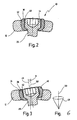
- Fig. 2
- einen Querschnitt durch die Befestigungsanordnung in
Fig. 1 entlang der Linie II-II inFig. 1 ; - Fig. 3
- einen Querschnitt durch die Befestigungsanordnung in
Fig. 1 entlang der Linie III-III inFig. 1 ; - Fig. 4
- einen Ausschnitt aus der Befestigungsanordnung in
Fig. 1 in einer derFig. 1 entsprechenden Darstellung, die die Funktion der Befestigungsanordnung beim Eindrehen der Schraube in den Untergrund in einem ersten Stadium zeigt; - Fig. 5
- eine der
Fig. 4 entsprechende Darstellung, in der die Schraube so weit in den Untergrund eingedreht ist, daß der Kopf der Schraube gerade mit der Hülse der Befestigungsanordnung in Eingriff kommt; und - Fig. 6
- eine schematische Darstellung der Beweglichkeit der Hülse um die Symmetrieachse der Bohrung des Befestigungsteils.
- In
Figuren 1 bis 3 ist eine mit dem allgemeinen Bezugszeichen 10 versehene Befestigungsanordnung zum Befestigen eines Befestigungsteils 12 an einem Untergrund 14 dargestellt. - In dem in den Figuren dargestellten Ausführungsbeispiel ist das Befestigungsteil 12 ein Riegel 16 in Form einer etwa rechteckigen länglichen Platte, der an einem Knochen 18 befestigt wird, der eine Fraktur 20 aufweist. Mittels des Riegels 16 werden zwei durch die Fraktur 20 getrennte Knochenteile 22 und 24 zur Heilung der Fraktur 20 aneinander fixiert.
- Der Riegel 16 ist mittels einer ersten Schraube 26 sowie einer zweiten Schraube 28 an dem Knochenteil 22 bzw. dem Knochenteil 24 befestigt. Die erste Schraube 26 und die zweite Schraube 28 sind Knochenschrauben, die jeweils ein an einem Schaft 27 bzw. 29 der Schraube 26 bzw. 28 ausgebildetes Gewinde 30 aufweisen, das beim Eindrehen der Schrauben 26 bzw. 28 ein entsprechendes Gewinde in die Knochenteile 22 bzw. 24 schneidet.
- In dem Riegel 16 ist eine erste Bohrung 32 und eine zweite Bohrung 34 vorgesehen, wobei in der ersten Bohrung 32 eine erste Hülse 36 und in der zweiten Bohrung 34 eine zweite Hülse 38 aufgenommen ist.
- Die erste Hülse 36 weist eine Aufnahme 40, und die zweite Hülse 38 weist eine Aufnahme 42 auf, die der Aufnahme eines Kopfes 44 der Schraube 26 bzw. der Aufnahme eines Kopfes 46 der Schraube 28 dienen. Der Kopf 44 der Schraube 26 und der Kopf 46 der Schraube 28 weisen jeweils einen Innensechskant 48 auf, der zur formschlüssigen Aufnahme eines Inbus-Schlüssels zum Eindrehen bzw. Ausdrehen der Schrauben 26 bzw. 28 dient.
- Die Hülsen 36 bzw. 38 sind in der Bohrung 32 bzw. 34 in mehreren, in dem gezeigten Ausführungsbeispiel in allen Raumrichtungen verkippbar gelagert. Diese Verkippbarkeit der Hülsen 36 und 38 besteht jedoch nur dann, wenn die Köpfe 44 bzw. 46 noch nicht in der Aufnahme 40 bzw. 42 der Hülse 36 bzw. 38 aufgenommen sind. In dem in
Figuren 1 bis 3 dargestellten Zustand, in dem die Köpfe 44 bzw. 46 in den Aufnahmen 40 bzw. 42 versenkt und die Schraube 26 bzw. 28 in dem Knochen 18 eingeschraubt sind, sind die Hülsen 36 bzw. 38 fixiert. Im inFiguren 1 bis 3 dargestellten endbefestigten Zustand ist das Befestigungsteil 12 vollkommen unbeweglich mit dem Untergrund 14 verbunden. - Die freie Verkippbarkeit der Hülse 36 bzw. 38 besteht jedoch so lange, wie die Köpfe 44 bzw. 46 der Schrauben 26 bzw. 28 noch nicht in die Aufnahme 40 der Hülse 36 bzw. in die Aufnahme 42 der Hülse 38 eingreifen, wie am Beispiel der Schraube 28 und der Hülse 38 in
Fig. 4 dargestellt ist. - Bei dem Ausführungsbeispiel gemäß
Figuren 1 bis 3 ist die Hülse 38 in der Bohrung 34 des Riegels 16 derart verkippt, daß eine Symmetrieachse 49 der Hülse 38 gegen eine Symmetrieachse 50 der Bohrung 34 bezüglich der Längsachse des Riegels 16 um einen Winkel α verkippt ist (vgl.Fig. 1 ) und in einer Richtung quer zur Längsachse des Riegels 16 um einen Winkel β (vgl.Fig. 3 ). Die freie Verkippbarkeit der Hülse 38 bewirkt, daß, wenn die Schraube 28, wie inFiguren 1 ,4 und 5 dargestellt ist, schräg in den Knochen 18 eingeschraubt wird, sich die Hülse 38 selbsttätig in der Bohrung 34 so positioniert, daß die Symmetrieachse 49 der Hülse 38 mit der Symmetrieachse der Schraube 28 zusammenfällt, so daß ein Verklemmen der Schraube 28 beim Eindrehen in den Knochen 18 mit der Hülse 38 vermieden wird. - Im vollkommen eingedrehten Zustand ist der Kopf 46 der Schraube 28 formschlüssig in der Aufnahme 42 der Hülse 38 aufgenommen. Das formschlüssige Eingreifen des Kopfes 46 in der Aufnahme 42 der Hülse 38 wird stets beim Eindrehen der Schrauben 26 und 28 automatisch erreicht, unabhängig davon, ob die Schraube 28 schräg in den Knochen 18 eingeschraubt wird, oder, wie im Falle der Schraube 26 dargestellt ist, ob die Schraube 26 lotrecht in den Knochen 18 eingeschraubt wird.
- Im vollkommen eingeschraubten Zustand der Schraube 26 bzw. 28 sitzt der Kopf 44 der Schraube 26 bzw. der Kopf 46 der Schraube 28 auf Preßsitz in der Aufnahme 40 bzw. 42 der Hülse 36 bzw. 38, wodurch die Hülse 36 und die Hülse 38 gegen die Wand der Bohrung 32 bzw. 34 gepreßt werden.
- Die Hülse 36 bzw. die Hülse 38 sind in der Bohrung 32 bzw. 34 über einen vollen Azimutalwinkel von 360° in einem Winkelbereich von 0° bis zumindest 45° verkippbar (vgl.
Fig. 6 ). InFig. 6 ist dies für einen Kippwinkel von etwa 10° gezeigt. - Bei dem in
Figuren 1 bis 3 gezeigten Ausführungsbeispiel sind die Hülsen 36 und 38 unmittelbar in den Bohrungen 32 bzw. 34 gelagert, und zwar sind die Hülsen 36 bzw. 38 in den Bohrungen 32 bzw. 34 formschlüssig aufgenommen. Aufgrund des Formschlusses sind die Hülsen 36 und 38 in den Bohrungen 32 und 34 unverlierbar gehalten. Eine Innenfläche 52 der Bohrung 32 des Riegels 16 und eine Außenfläche 54 der Hülse 36 sind dazu sphärisch gewölbt ausgebildet, wobei die Innenfläche 52 der Bohrung 32 sphärisch konkav und die Außenfläche 54 der Hülse 36 sphärisch konvex ausgebildet ist. Dabei befindet sich ein Bereich 56 größten Durchmessers der Innenfläche 52 und der Außenfläche 54 zwischen einem oberen Rand 58 der Bohrung 32 und einem unteren Rand 60 der Bohrung 32. Durch diese Ausgestaltung ist die Hülse 36 unverlierbar, jedoch in allen Raumrichtungen frei verkippbar in der Bohrung 32 aufgenommen. Die Hülse 38 und die Bohrung 34 sind entsprechend ausgestaltet. - Ferner ist ein oberer Rand 62 der Hülse 36 abgerundet ausgebildet, ebenso bei der Hülse 38. An dem Kopf 44 der Schraube 26 ist (wie an dem Kopf 46 der Schraube 28) in einem sich radial nach unten verjüngenden Umfangsbereich eine Abstützfläche 64 ausgebildet, die sich in dem in
Fig. 1 dargestellten befestigten Zustand des Riegels 16 auf einer etwa komplementär dazu ausgebildeten Abstützfläche 66 der Hülse 36 abstützt. Insgesamt liegt der Kopf 44 in in der Aufnahme 40 der Hülse 36 vollkommen versenkter Lage flächig in der Aufnahme 40 der Hülse 36 an. Die gegeneinanderdrückenden, schräg ausgebildeten Abstützflächen 64 bzw. 66 bewirken dabei eine leichte Dehnung der Hülse 36, durch die die Verankerung und Verpressung des Schraubenkopfes 44 in der Hülse 36 verbessert wird. - Wie aus
Figuren 1 bis 3 hervorgeht, weist der Kopf 44 der Schraube 26 außerdem etwa die gleiche Höhe auf wie die Aufnahme 40 der Hülse 36, und ebenso weist die Hülse 36 in etwa die gleiche Höhe auf wie die Bohrung 32, so daß der obere Rand 62 der Hülse 36 mit der Oberseite des Kopfes 44 der Schraube 26 und der Oberseite des Riegels 16 eine im wesentlichen gleichmäßige Fläche bildet. - Bei dem mit Bezug auf
Figuren 1 bis 3 beschriebenen Ausführungsbeispiel sind die Hülsen 36, 38 einstückig aus Metall oder aus Kunststoff gefertigt, oder weisen einen Metallkorpus auf, wobei die jeweilige in den Hülsen 36, 38 ausgebildeten Aufnahmen 40, 42 zumindest teilweise mit Kunststoff ausgekleidet sind. - Während die Befestigungsanordnung 10 für einen speziellen Anwendungsfall im medizinischen Bereich zur Befestigung eines Riegels 16 an einem Knochen 18 beschrieben wurde, versteht es sich von selbst, daß eine derartige Befestigungsanordnung auch für technische Zwecke verwendbar ist, beispielsweise um in häuslichen Anwendungen Befestigungsteile, wie Platten, Riegel, Winkel, Halter usw., an einer Wand oder einer Decke zu befestigen.
Claims (8)
- Befestigungsanordnung zum Befestigen eines Befestigungsteils (12) beispielsweise einer Platte, eines Riegels (16), eines Winkels, eines Profils, eines Beschlags, eines. Halters oder dergleichen, an einem Untergrund (14) mittels zumindest einer Schraube (26, 28), die durch zumindest eine Bohrung (32, 34) in dem Befestigungsteil (12) durchführbar und in den Untergrund (14) einschraubbar ist, wobei unmittelbar in der Bohrung (32, 34) eine in mehreren Raumrichtungen verkippbar gelagerte Hülse (36, 38), angeordnet ist, durch die die Schraube (26, 28) zum Eindrehen in den Untergrund (14) durchgeführt wird, und wobei die Hülse (36, 38) eine Aufnahme (40, 42) zum zumindest teilweisen flächigen Aufnehmen eines Kopfes (44, 46) der Schraube (26, 28) aufweist, wobei eine Innenfläche (52) der Bohrung (32, 34) und eine AuBenfläche (54) der Hülse (36, 38) etwa sphärisch gewölbt ausgebildet sind, wobei sich ein Bereich (56) größten Durchmessers der Innenfläche (52) und der Außenfläche (54) zwischen einem oberen Rand (58) der Bohrung (32, 34) und einem unteren Rand (60) der Bohrung (32, 34) befindet, und wobei die Hülse (36, 38) in die Bohrung (32, 34) formschlüssig unverlierbar eingepreßt ist, dadurch gekennzeichnet, daß ein Umfangsbereich des Kopfes (44, 46) der Schraube (26, 28) als Abstützfläche (64) ausgebildet ist, die sich im angezogenen Zustand der Schraube (26, 28) auf einer etwa komplementär zur Abstützfläche (64) des Kopfes (44, 46) ausgebildeten Abstützfläche (66) der Hülse (36, 38) abstützt.
- Befestigungsanordnung nach Anspruch 1, dadurch gekennzeichnet, daß eine Symmetrieachse (48) der Hülse (36, 38) gegen eine Symmetrieachse (50) der Bohrung (32, 34) über vorzugsweise einen vollen Azimutalwinkel von 360° in einem Winkelbereich von 0° bis zumindest 45° verkippbar ist.
- Befestigungsanordnung nach Anspruch 1 oder 2, dadurch gekennzeichnet, daß der Kopf (44, 46) der Schraube (26, 28) und die Aufnahme (40, 42) der Hülse (36, 38) eine im wesentlichen formschlüssige Verbindung bilden.
- Befestigungsanordnung nach einem der Ansprüche 1 bis 3, dadurch gekennzeichnet, daß der Kopf der Schraube und die Aufnahme der Hülse komplementär zueinander konisch ausgebildet sind.
- Befestigungsanordnung nach einem der Ansprüche 1 bis 4, dadurch gekennzeichnet, daß ein oberer Rand (62) der Aufnahme (40) der Hülse (36) abgerundet ist.
- Befestigungsanordnung nach einem der Ansprüche 1 bis 5, dadurch gekennzeichnet, daß die Hülse (36, 38) in etwa die gleiche Höhe aufweist wie die Bohrung (32, 34), und daß der Kopf (44, 46) der Schraube (26, 28) in etwa die gleiche Höhe aufweist wie die Aufnahme (40, 42) der Hülse (36, 38).
- Befestigungsanordnung nach einem der Ansprüche 1 bis 6, dadurch gekennzeichnet, daß die Hülse (36, 38) einstückig aus Metall oder aus Kunststoff gefertigt ist, oder einen Metallkorpus aufweist, wobei die Aufnahme (40, 42) der Hülse (36, 38) dann zumindest teilweise mit Kunststoff ausgekleidet ist.
- Verwendung einer Befestigungsanordnung nach einem der Ansprüche 1 bis 7 zum Anbringen eines Gegenstandes an einer Wand, wobei das Befestigungsteil (12) ein Wandbeschlag, ein Profil oder dergleichen ist, oder zur Montage von Möbeln oder dergleichen, wobei das Befestigungsteil ein Beschlag, ein Scharnier, ein Winkel oder dergleichen ist.
Applications Claiming Priority (3)
| Application Number | Priority Date | Filing Date | Title |
|---|---|---|---|
| DE19832513A DE19832513A1 (de) | 1998-07-20 | 1998-07-20 | Befestigungsanordnung |
| DE19832513 | 1998-07-20 | ||
| PCT/EP1999/004973 WO2000004836A1 (de) | 1998-07-20 | 1999-07-14 | Befestigungsanordnung |
Publications (3)
| Publication Number | Publication Date |
|---|---|
| EP1098602A1 EP1098602A1 (de) | 2001-05-16 |
| EP1098602B1 EP1098602B1 (de) | 2003-06-25 |
| EP1098602B2 true EP1098602B2 (de) | 2010-08-25 |
Family
ID=7874631
Family Applications (1)
| Application Number | Title | Priority Date | Filing Date |
|---|---|---|---|
| EP99938239A Expired - Lifetime EP1098602B2 (de) | 1998-07-20 | 1999-07-14 | Befestigungsanordnung |
Country Status (5)
| Country | Link |
|---|---|
| US (2) | US7229443B2 (de) |
| EP (1) | EP1098602B2 (de) |
| AT (1) | ATE243471T1 (de) |
| DE (2) | DE19832513A1 (de) |
| WO (1) | WO2000004836A1 (de) |
Families Citing this family (117)
| Publication number | Priority date | Publication date | Assignee | Title |
|---|---|---|---|---|
| DE10039767B4 (de) | 2000-01-20 | 2014-08-21 | Biedermann Technologies Gmbh & Co. Kg | Befestigungsanordnung |
| US7695502B2 (en) | 2000-02-01 | 2010-04-13 | Depuy Products, Inc. | Bone stabilization system including plate having fixed-angle holes together with unidirectional locking screws and surgeon-directed locking screws |
| US6767351B2 (en) | 2000-02-01 | 2004-07-27 | Hand Innovations, Inc. | Fixation system with multidirectional stabilization pegs |
| US20040153073A1 (en) * | 2000-02-01 | 2004-08-05 | Hand Innovations, Inc. | Orthopedic fixation system including plate element with threaded holes having divergent axes |
| US7857838B2 (en) | 2003-03-27 | 2010-12-28 | Depuy Products, Inc. | Anatomical distal radius fracture fixation plate |
| US6706046B2 (en) | 2000-02-01 | 2004-03-16 | Hand Innovations, Inc. | Intramedullary fixation device for metaphyseal long bone fractures and methods of using the same |
| DE60119732T2 (de) * | 2000-05-31 | 2007-02-22 | Vese, Silvana | Befestigungsvorrichtung für knochenplatte |
| WO2002000124A1 (fr) * | 2000-06-30 | 2002-01-03 | Sdgi Holdings, Inc. | Dispositif de liaison intervertebral |
| US6679883B2 (en) * | 2001-10-31 | 2004-01-20 | Ortho Development Corporation | Cervical plate for stabilizing the human spine |
| DE10156402A1 (de) * | 2001-11-13 | 2003-05-22 | Newfrey Llc | Befestigungsanordnung |
| US7070599B2 (en) | 2002-07-24 | 2006-07-04 | Paul Kamaljit S | Bone support assembly |
| US6755833B1 (en) | 2001-12-14 | 2004-06-29 | Kamaljit S. Paul | Bone support assembly |
| AU2002220448B2 (en) | 2001-12-24 | 2005-06-30 | Synthes Gmbh | Device for performing osteosynthesis |
| US7077843B2 (en) * | 2002-06-24 | 2006-07-18 | Lanx, Llc | Cervical plate |
| US7758620B2 (en) * | 2002-09-24 | 2010-07-20 | Stryker Trauma Sa | Device for connecting a screw to a support plate |
| AU2002351649B2 (en) * | 2002-12-02 | 2006-08-24 | Synthes Gmbh | Implant for fixing bones |
| US7425213B2 (en) | 2002-12-10 | 2008-09-16 | Depuy Products, Inc. | Method of endosteal nailing |
| US7686837B2 (en) * | 2003-02-03 | 2010-03-30 | Stryker Trauma S.A. | Polyaxial locking implantable orthopedic fixation device |
| US8172885B2 (en) | 2003-02-05 | 2012-05-08 | Pioneer Surgical Technology, Inc. | Bone plate system |
| ATE450221T1 (de) * | 2003-04-03 | 2009-12-15 | Medartis Ag | Aufnahme für ein verblockungselement und verblockungselement |
| US7909829B2 (en) | 2003-06-27 | 2011-03-22 | Depuy Spine, Inc. | Tissue retractor and drill guide |
| US7776047B2 (en) | 2003-04-09 | 2010-08-17 | Depuy Spine, Inc. | Guide for spinal tools, implants, and devices |
| US7416553B2 (en) | 2003-04-09 | 2008-08-26 | Depuy Acromed, Inc. | Drill guide and plate inserter |
| US7935123B2 (en) | 2003-04-09 | 2011-05-03 | Depuy Acromed, Inc. | Drill guide with alignment feature |
| US7951176B2 (en) | 2003-05-30 | 2011-05-31 | Synthes Usa, Llc | Bone plate |
| US7909848B2 (en) | 2003-06-27 | 2011-03-22 | Depuy Spine, Inc. | Tissue retractor and guide device |
| NZ545392A (en) | 2003-08-26 | 2008-03-28 | Synthes Gmbh | Bone plate |
| US11259851B2 (en) | 2003-08-26 | 2022-03-01 | DePuy Synthes Products, Inc. | Bone plate |
| CN100475168C (zh) | 2003-09-08 | 2009-04-08 | 斯恩蒂斯有限公司 | 用于骨固定术的装置 |
| CA2545019C (en) | 2003-10-30 | 2012-02-28 | Synthes Gmbh | Bone plate |
| DE20317196U1 (de) * | 2003-11-05 | 2004-01-15 | A. Agrati S.P.A., Veduggio Con Colzano | Radschraubenanordnung für PKW oder sonstige Fahrzeuge |
| US7655009B2 (en) | 2003-12-01 | 2010-02-02 | Smith & Nephew, Inc. | Humeral nail |
| US7637928B2 (en) | 2004-01-26 | 2009-12-29 | Synthes Usa, Llc | Variable angle locked bone fixation system |
| US8574268B2 (en) | 2004-01-26 | 2013-11-05 | DePuy Synthes Product, LLC | Highly-versatile variable-angle bone plate system |
| US11291484B2 (en) | 2004-01-26 | 2022-04-05 | DePuy Synthes Products, Inc. | Highly-versatile variable-angle bone plate system |
| JP4863885B2 (ja) * | 2004-02-23 | 2012-01-25 | ジンテーズ ゲゼルシャフト ミト ベシュレンクテル ハフツング | 骨ねじ |
| US7740649B2 (en) | 2004-02-26 | 2010-06-22 | Pioneer Surgical Technology, Inc. | Bone plate system and methods |
| US8900277B2 (en) | 2004-02-26 | 2014-12-02 | Pioneer Surgical Technology, Inc. | Bone plate system |
| US7854752B2 (en) | 2004-08-09 | 2010-12-21 | Theken Spine, Llc | System and method for dynamic skeletal stabilization |
| US9615866B1 (en) | 2004-10-18 | 2017-04-11 | Nuvasive, Inc. | Surgical fixation system and related methods |
| US9055981B2 (en) | 2004-10-25 | 2015-06-16 | Lanx, Inc. | Spinal implants and methods |
| US8241330B2 (en) | 2007-01-11 | 2012-08-14 | Lanx, Inc. | Spinous process implants and associated methods |
| JP4922184B2 (ja) * | 2004-12-23 | 2012-04-25 | ストーブリ,ハンス,ウルリッヒ | 骨固定装置 |
| US7410488B2 (en) | 2005-02-18 | 2008-08-12 | Smith & Nephew, Inc. | Hindfoot nail |
| DE502006006702D1 (de) * | 2005-03-24 | 2010-05-27 | Medartis Ag | Knochenplatte |
| US7931681B2 (en) | 2005-04-14 | 2011-04-26 | Warsaw Orthopedic, Inc. | Anti-backout mechanism for an implant fastener |
| EP1876975A2 (de) | 2005-04-27 | 2008-01-16 | James Marino | Verfahren, system und satz mit einer monoplanaren pedikelschraube |
| US7905909B2 (en) | 2005-09-19 | 2011-03-15 | Depuy Products, Inc. | Bone stabilization system including multi-directional threaded fixation element |
| SE531987C2 (sv) * | 2006-03-17 | 2009-09-22 | Sven Olerud | Anordning för att fästa och fixera ett första element mot ett andra element |
| US8025681B2 (en) | 2006-03-29 | 2011-09-27 | Theken Spine, Llc | Dynamic motion spinal stabilization system |
| US8361130B2 (en) * | 2006-10-06 | 2013-01-29 | Depuy Spine, Inc. | Bone screw fixation |
| US8287575B2 (en) * | 2006-11-09 | 2012-10-16 | Stryker Trauma Gmbh | Polyaxial locking mechanism |
| US9265532B2 (en) * | 2007-01-11 | 2016-02-23 | Lanx, Inc. | Interspinous implants and methods |
| US7722611B2 (en) * | 2007-03-05 | 2010-05-25 | Depuy Products, Inc. | Method of treating a clavicle fracture |
| US8702762B2 (en) * | 2007-03-27 | 2014-04-22 | Depuy Spine, Inc. | Passive screw locking mechanism |
| EP1987792B1 (de) | 2007-05-03 | 2011-06-22 | Medartis AG | Fixiervorrichtung, Kombination einer Fixiervorrichtung mit einem länglichen Element, Anordnung mit einer solchen Kombination sowie Osteosyntheseset |
| WO2009006604A1 (en) | 2007-07-03 | 2009-01-08 | Pioneer Surgical Technology, Inc. | Bone plate system |
| US8361126B2 (en) | 2007-07-03 | 2013-01-29 | Pioneer Surgical Technology, Inc. | Bone plate system |
| US9101410B1 (en) * | 2007-10-24 | 2015-08-11 | Robert E. Urrea | Facet joint fusion device and method for using same |
| US8282675B2 (en) * | 2008-01-25 | 2012-10-09 | Depuy Spine, Inc. | Anti-backout mechanism |
| US20090248087A1 (en) * | 2008-03-03 | 2009-10-01 | Orthohelix Surgical Designs, Inc. | Variable axis locking mechanism for use in orthopedic implants |
| US8480716B2 (en) * | 2008-04-25 | 2013-07-09 | Pioneer Surgical Technology, Inc. | Bone plate system |
| CA2725472C (en) * | 2008-06-03 | 2016-08-02 | Synthes Usa, Llc | Variable angle fixation element system |
| DE102009037820C5 (de) * | 2008-08-11 | 2022-03-24 | Adolf Würth Gmbh & Co Kg | Anordnung zur Verbindung von Holzbauteilen |
| US8137405B2 (en) * | 2008-10-08 | 2012-03-20 | K2M, Inc. | Spinal interbody spacer |
| JP2012505668A (ja) * | 2008-10-14 | 2012-03-08 | ケー2エム, インコーポレイテッド | 半拘束型ねじおよび脊椎プレート・アセンブリ |
| DE202008017215U1 (de) * | 2008-12-22 | 2009-04-16 | Simpson Strong-Tie Gmbh | Zwischenelement für eine Schrägschraubverbindung |
| US8486115B2 (en) * | 2009-03-13 | 2013-07-16 | Lanx, Inc. | Spinal plate assemblies with backout protection cap and methods |
| EP2413825A4 (de) | 2009-03-31 | 2013-12-11 | Lanx Inc | Dornfortsatzimplantate und zugehörige verfahren |
| US8211154B2 (en) * | 2009-04-06 | 2012-07-03 | Lanx, Inc. | Bone plate assemblies with backout protection and visual indicator |
| US20110000342A1 (en) * | 2009-07-02 | 2011-01-06 | TR Tools, L.L.C. | Wrench |
| US9259255B2 (en) | 2009-07-15 | 2016-02-16 | Orthohelix Surgical Designs, Inc. | Variable axis locking mechanism for use in orthopedic implants |
| EP2477566B1 (de) | 2009-09-14 | 2017-03-22 | Synthes GmbH | Druckplatte mit veränderlichem winkel |
| USD754857S1 (en) | 2009-10-14 | 2016-04-26 | Nuvasive, Inc. | Bone plate |
| US8449585B2 (en) * | 2009-11-05 | 2013-05-28 | K2M, Inc. | Semi-constrained bone screw |
| US8444680B2 (en) * | 2009-11-09 | 2013-05-21 | Arthrex, Inc. | Polyaxial bushing for locking plate |
| US8808335B2 (en) | 2010-03-08 | 2014-08-19 | Miami Device Solutions, Llc | Locking element for a polyaxial bone anchor, bone plate assembly and tool |
| US9113970B2 (en) | 2010-03-10 | 2015-08-25 | Orthohelix Surgical Designs, Inc. | System for achieving selectable fixation in an orthopedic plate |
| US8377139B2 (en) | 2010-06-17 | 2013-02-19 | Aesculap Implant Systems, Llc | Standalone interbody fusion device with locking and release mechanism |
| EP2460484A1 (de) * | 2010-12-01 | 2012-06-06 | FACET-LINK Inc. | Winkelvariable Knochenschauben-Fixationsanordnung |
| US9468535B2 (en) | 2010-12-17 | 2016-10-18 | K2M, Inc. | Interbody spacer |
| US9358122B2 (en) | 2011-01-07 | 2016-06-07 | K2M, Inc. | Interbody spacer |
| US20120191138A1 (en) * | 2011-01-21 | 2012-07-26 | Kiester P Douglas | Use of flexible bushings to promote healing and stable fracture compression in orthopedic trauma plates |
| US9017409B2 (en) | 2011-04-22 | 2015-04-28 | K2M, Inc. | Spinal interbody spacer with semi-constrained screws |
| US8771324B2 (en) | 2011-05-27 | 2014-07-08 | Globus Medical, Inc. | Securing fasteners |
| US11812923B2 (en) | 2011-10-07 | 2023-11-14 | Alan Villavicencio | Spinal fixation device |
| DE102011089519A1 (de) * | 2011-12-22 | 2013-06-27 | Bayerische Motoren Werke Aktiengesellschaft | Verbindungselement |
| US9198769B2 (en) | 2011-12-23 | 2015-12-01 | Pioneer Surgical Technology, Inc. | Bone anchor assembly, bone plate system, and method |
| ITTO20120168A1 (it) * | 2012-02-24 | 2013-08-25 | Medicomp S R L | Sistema di fissaggio multi-assiale per osteosintesi |
| US10292832B2 (en) | 2013-03-14 | 2019-05-21 | Ohio State Innovation Foundation | Spinal fixation device |
| US9707096B2 (en) | 2013-03-14 | 2017-07-18 | K2M, Inc. | Spinal fixation device |
| US9510880B2 (en) | 2013-08-13 | 2016-12-06 | Zimmer, Inc. | Polyaxial locking mechanism |
| US9468479B2 (en) | 2013-09-06 | 2016-10-18 | Cardinal Health 247, Inc. | Bone plate |
| US20170000497A1 (en) | 2013-11-29 | 2017-01-05 | The Johns Hopkins University | Cranial reference mount |
| US10213237B2 (en) | 2014-10-03 | 2019-02-26 | Stryker European Holdings I, Llc | Periprosthetic extension plate |
| US10603175B2 (en) | 2014-11-24 | 2020-03-31 | The Johns Hopkins University | Cutting machine for resizing raw implants during surgery |
| AU2015353523B2 (en) | 2014-11-24 | 2019-10-24 | The Johns Hopkins University | Computer-assisted cranioplasty |
| JP6552725B2 (ja) * | 2015-08-31 | 2019-07-31 | ファウ・エス・エル・インターナツイオナール・アクチエンゲゼルシヤフト | ケーブル係留システム |
| US11058541B2 (en) | 2015-09-04 | 2021-07-13 | The Johns Hopkins University | Low-profile intercranial device |
| EP3349695B1 (de) | 2015-09-18 | 2020-11-18 | K2M, Inc. | Korpektomievorrichtung |
| US10105169B2 (en) * | 2015-11-13 | 2018-10-23 | Leith Medical LLC | Bone fixation systems, apparatuses, and methods with anti-back-out feature |
| US10251685B2 (en) | 2016-03-17 | 2019-04-09 | Stryker European Holdings I, Llc | Floating locking insert |
| US10820930B2 (en) | 2016-09-08 | 2020-11-03 | DePuy Synthes Products, Inc. | Variable angle bone plate |
| US10624686B2 (en) | 2016-09-08 | 2020-04-21 | DePuy Synthes Products, Inc. | Variable angel bone plate |
| US10905476B2 (en) | 2016-09-08 | 2021-02-02 | DePuy Synthes Products, Inc. | Variable angle bone plate |
| US11026727B2 (en) | 2018-03-20 | 2021-06-08 | DePuy Synthes Products, Inc. | Bone plate with form-fitting variable-angle locking hole |
| US10772665B2 (en) | 2018-03-29 | 2020-09-15 | DePuy Synthes Products, Inc. | Locking structures for affixing bone anchors to a bone plate, and related systems and methods |
| US11013541B2 (en) | 2018-04-30 | 2021-05-25 | DePuy Synthes Products, Inc. | Threaded locking structures for affixing bone anchors to a bone plate, and related systems and methods |
| US10925651B2 (en) | 2018-12-21 | 2021-02-23 | DePuy Synthes Products, Inc. | Implant having locking holes with collection cavity for shavings |
| EP3795104A1 (de) * | 2019-09-18 | 2021-03-24 | Kyon AG | Wulstkopf zum verriegeln von knochenschrauben |
| MX2022004548A (es) | 2019-10-14 | 2022-08-08 | Leith Medical LLC | Aparato para la estabilizacion de un sitio de fractura osea. |
| MX2022004471A (es) | 2019-10-14 | 2022-08-16 | Leith Medical LLC | Un sistema de fijación de hueso con sujetadores y una herramienta de remoción para desacoplarse de los sujetadores. |
| US11877779B2 (en) | 2020-03-26 | 2024-01-23 | Xtant Medical Holdings, Inc. | Bone plate system |
| US20230375023A1 (en) * | 2020-09-21 | 2023-11-23 | Ikea Supply Ag | Furniture, connectors and joints thereof, and a method for assembling such furniture |
| WO2022074255A1 (en) * | 2020-10-09 | 2022-04-14 | Siso A/S | Adjustable fastening device for a furniture leg |
| US11084085B1 (en) * | 2020-10-23 | 2021-08-10 | Ford Global Technologies, Llc | Vehicle component joining method |
| CN112672560A (zh) * | 2020-12-18 | 2021-04-16 | 北京无线电计量测试研究所 | 一种控温装置 |
Citations (2)
| Publication number | Priority date | Publication date | Assignee | Title |
|---|---|---|---|---|
| EP0355035B1 (de) † | 1987-11-03 | 1994-05-18 | SYNTHES AG, Chur | Knochenplatte mit konischen Löchern |
| US5735853A (en) † | 1994-06-17 | 1998-04-07 | Olerud; Sven | Bone screw for osteosynthesis |
Family Cites Families (15)
| Publication number | Priority date | Publication date | Assignee | Title |
|---|---|---|---|---|
| DE2530854C3 (de) * | 1975-01-03 | 1980-01-24 | Guenter 5013 Elsdorf Busch | Vorrichtung für die Befestigung von Holzzargen u.dgl |
| CH645264A5 (de) * | 1980-05-28 | 1984-09-28 | Straumann Inst Ag | Einrichtung mit einer platte und zu deren befestigung an einem knochen dienenden schrauben. |
| DE3420696C1 (de) * | 1984-06-02 | 1985-10-10 | Flachglas AG, 8510 Fürth | Klemmbeschlag für die Befestigung und/oder Verbindung von Glasscheiben, insbesondere für Fassadenplatten aus Einscheibensicherheitsglas |
| WO1989004150A1 (en) * | 1987-11-03 | 1989-05-18 | Synthes Ag | Implant for osteosynthesis |
| US5057111A (en) * | 1987-11-04 | 1991-10-15 | Park Joon B | Non-stress-shielding bone fracture healing device |
| US4971497A (en) * | 1990-03-02 | 1990-11-20 | The United States Of America As Represented By The Secretary Of The Air Force | Fastener system |
| CH686339A5 (de) * | 1991-12-10 | 1996-03-15 | Synthes Ag | Schraubenmutter fuer die Plattenosteosynthese. |
| US5395194A (en) * | 1993-10-13 | 1995-03-07 | H. Thad Johnson | Convoluted bolt retainer |
| CA2158890C (en) * | 1995-09-22 | 2002-01-22 | John Runciman | Spherical washer for use with a bone screw |
| AU1997797A (en) * | 1996-05-31 | 1997-12-04 | Acromed Corporation | An apparatus comprising a plate and a fastener for connecting the plate to a bone portion |
| EP0845609A1 (de) * | 1996-11-26 | 1998-06-03 | Beracon AG | Nivellierschraube und Befestigungsvorrichtung mit einer Nivellierschraube |
| DE19702201C1 (de) * | 1997-01-23 | 1998-08-06 | Aesculap Ag & Co Kg | Stiftförmiges Halteelement für ein orthopädisches Haltesystem |
| US5954722A (en) * | 1997-07-29 | 1999-09-21 | Depuy Acromed, Inc. | Polyaxial locking plate |
| US6656181B2 (en) * | 2000-11-22 | 2003-12-02 | Robert A Dixon | Method and device utilizing tapered screw shanks for spinal stabilization |
| US7311712B2 (en) * | 2004-02-26 | 2007-12-25 | Aesculap Implant Systems, Inc. | Polyaxial locking screw plate assembly |
-
1998
- 1998-07-20 DE DE19832513A patent/DE19832513A1/de not_active Withdrawn
-
1999
- 1999-07-14 AT AT99938239T patent/ATE243471T1/de not_active IP Right Cessation
- 1999-07-14 EP EP99938239A patent/EP1098602B2/de not_active Expired - Lifetime
- 1999-07-14 WO PCT/EP1999/004973 patent/WO2000004836A1/de not_active Ceased
- 1999-07-14 DE DE59906110T patent/DE59906110D1/de not_active Expired - Lifetime
-
2001
- 2001-01-18 US US09/764,936 patent/US7229443B2/en not_active Expired - Lifetime
-
2007
- 2007-05-18 US US11/804,572 patent/US8388665B2/en not_active Expired - Fee Related
Patent Citations (2)
| Publication number | Priority date | Publication date | Assignee | Title |
|---|---|---|---|---|
| EP0355035B1 (de) † | 1987-11-03 | 1994-05-18 | SYNTHES AG, Chur | Knochenplatte mit konischen Löchern |
| US5735853A (en) † | 1994-06-17 | 1998-04-07 | Olerud; Sven | Bone screw for osteosynthesis |
Also Published As
| Publication number | Publication date |
|---|---|
| US20080058817A1 (en) | 2008-03-06 |
| DE19832513A1 (de) | 2000-02-17 |
| ATE243471T1 (de) | 2003-07-15 |
| US20010021851A1 (en) | 2001-09-13 |
| EP1098602A1 (de) | 2001-05-16 |
| EP1098602B1 (de) | 2003-06-25 |
| DE59906110D1 (de) | 2003-07-31 |
| US8388665B2 (en) | 2013-03-05 |
| US7229443B2 (en) | 2007-06-12 |
| WO2000004836A1 (de) | 2000-02-03 |
Similar Documents
| Publication | Publication Date | Title |
|---|---|---|
| EP1098602B1 (de) | Befestigungsanordnung | |
| EP0633750B1 (de) | Gegenspannscheibe für die plattenosteosynthese | |
| EP2023833B1 (de) | Implantat mit fixierelement | |
| WO1996028105A1 (de) | Element zur halswirbelstabilisierung | |
| DE10256095A1 (de) | Element mit einem Schaft und einem damit verbundenen Halteelement zum Verbinden mit einem Stab | |
| DE8601106U1 (de) | Einstellbare Befestigungsvorrichtung zum Zusammenfügen von zwei Bauteilen | |
| EP1501993B1 (de) | Anordnung mit türblatt und scharnieren sowie duschkabine | |
| EP0691478A2 (de) | Befestigungsvorrichtung für ein mit einer Befestigungsbohrung versehenes Beschlagteil, vorzugsweise für ein Scharnierteil | |
| DE10039767B4 (de) | Befestigungsanordnung | |
| DE19641500C2 (de) | Vorrichtung zum lösbaren Verbinden von Profilstäben | |
| DE19755953C2 (de) | Schraube zur Abstandsbefestigung von Abdeckplatten oder Schienen an einem Unterbau | |
| DE102009037820C5 (de) | Anordnung zur Verbindung von Holzbauteilen | |
| EP1034379B1 (de) | Schraube zur abstandsbefestigung von abdeckplatten oder schienen an einem unterbau | |
| DE4316038A1 (de) | Dübelanordnung, insbesondere zur Befestigung von Möbelbeschlägen | |
| DE29920945U1 (de) | Möbelscharnier | |
| EP2514892B1 (de) | System zur Befestigung eines Beschlagteils | |
| EP0760890B1 (de) | Mehrteiliges scharnier | |
| DE10210627C1 (de) | Vorrichtung zum Verbinden wenigstens zweier Bauteile | |
| EP0950819A2 (de) | Befestigungsanordnung | |
| DE60016484T2 (de) | Verfahren und Befestigungsvorrichtung zur Montage von Türbeschlägen | |
| EP0898658B1 (de) | Befestigungselement für den einsatz in hinterschnittene profilnuten | |
| EP1010398B1 (de) | Pedikelschraube | |
| EP0996804A1 (de) | Bandteil zur anordnung an holz- oder metallzargen für fenster oder türen | |
| DE7534416U (de) | Vorrichtung zum befestigen eines einbaugeraetes in einem gehaeuse | |
| CH634627A5 (en) | Hinge for wings, especially for windows, doors or furniture |
Legal Events
| Date | Code | Title | Description |
|---|---|---|---|
| PUAI | Public reference made under article 153(3) epc to a published international application that has entered the european phase |
Free format text: ORIGINAL CODE: 0009012 |
|
| 17P | Request for examination filed |
Effective date: 20010118 |
|
| AK | Designated contracting states |
Kind code of ref document: A1 Designated state(s): AT BE CH CY DE DK ES FI FR GB GR IE IT LI LU MC NL PT SE |
|
| 17Q | First examination report despatched |
Effective date: 20010706 |
|
| GRAG | Despatch of communication of intention to grant |
Free format text: ORIGINAL CODE: EPIDOS AGRA |
|
| GRAG | Despatch of communication of intention to grant |
Free format text: ORIGINAL CODE: EPIDOS AGRA |
|
| GRAH | Despatch of communication of intention to grant a patent |
Free format text: ORIGINAL CODE: EPIDOS IGRA |
|
| GRAH | Despatch of communication of intention to grant a patent |
Free format text: ORIGINAL CODE: EPIDOS IGRA |
|
| GRAA | (expected) grant |
Free format text: ORIGINAL CODE: 0009210 |
|
| RAP1 | Party data changed (applicant data changed or rights of an application transferred) |
Owner name: BIEDERMANN MOTECH GMBH |
|
| AK | Designated contracting states |
Designated state(s): AT BE CH CY DE DK ES FI FR GB GR IE IT LI LU MC NL PT SE |
|
| PG25 | Lapsed in a contracting state [announced via postgrant information from national office to epo] |
Ref country code: NL Free format text: LAPSE BECAUSE OF FAILURE TO SUBMIT A TRANSLATION OF THE DESCRIPTION OR TO PAY THE FEE WITHIN THE PRESCRIBED TIME-LIMIT Effective date: 20030625 Ref country code: IT Free format text: LAPSE BECAUSE OF FAILURE TO SUBMIT A TRANSLATION OF THE DESCRIPTION OR TO PAY THE FEE WITHIN THE PRESCRIBED TIME-LIMIT;WARNING: LAPSES OF ITALIAN PATENTS WITH EFFECTIVE DATE BEFORE 2007 MAY HAVE OCCURRED AT ANY TIME BEFORE 2007. THE CORRECT EFFECTIVE DATE MAY BE DIFFERENT FROM THE ONE RECORDED. Effective date: 20030625 Ref country code: IE Free format text: LAPSE BECAUSE OF FAILURE TO SUBMIT A TRANSLATION OF THE DESCRIPTION OR TO PAY THE FEE WITHIN THE PRESCRIBED TIME-LIMIT Effective date: 20030625 Ref country code: FI Free format text: LAPSE BECAUSE OF FAILURE TO SUBMIT A TRANSLATION OF THE DESCRIPTION OR TO PAY THE FEE WITHIN THE PRESCRIBED TIME-LIMIT Effective date: 20030625 |
|
| REG | Reference to a national code |
Ref country code: GB Ref legal event code: FG4D Free format text: NOT ENGLISH |
|
| REG | Reference to a national code |
Ref country code: CH Ref legal event code: EP |
|
| PG25 | Lapsed in a contracting state [announced via postgrant information from national office to epo] |
Ref country code: LU Free format text: LAPSE BECAUSE OF NON-PAYMENT OF DUE FEES Effective date: 20030714 Ref country code: CY Free format text: LAPSE BECAUSE OF FAILURE TO SUBMIT A TRANSLATION OF THE DESCRIPTION OR TO PAY THE FEE WITHIN THE PRESCRIBED TIME-LIMIT Effective date: 20030714 Ref country code: AT Free format text: LAPSE BECAUSE OF NON-PAYMENT OF DUE FEES Effective date: 20030714 |
|
| GBT | Gb: translation of ep patent filed (gb section 77(6)(a)/1977) | ||
| REG | Reference to a national code |
Ref country code: IE Ref legal event code: FG4D Free format text: GERMAN |
|
| PG25 | Lapsed in a contracting state [announced via postgrant information from national office to epo] |
Ref country code: MC Free format text: LAPSE BECAUSE OF NON-PAYMENT OF DUE FEES Effective date: 20030731 Ref country code: BE Free format text: LAPSE BECAUSE OF NON-PAYMENT OF DUE FEES Effective date: 20030731 |
|
| REF | Corresponds to: |
Ref document number: 59906110 Country of ref document: DE Date of ref document: 20030731 Kind code of ref document: P |
|
| REG | Reference to a national code |
Ref country code: CH Ref legal event code: NV Representative=s name: R. A. EGLI & CO. PATENTANWAELTE |
|
| PG25 | Lapsed in a contracting state [announced via postgrant information from national office to epo] |
Ref country code: SE Free format text: LAPSE BECAUSE OF FAILURE TO SUBMIT A TRANSLATION OF THE DESCRIPTION OR TO PAY THE FEE WITHIN THE PRESCRIBED TIME-LIMIT Effective date: 20030925 Ref country code: PT Free format text: LAPSE BECAUSE OF FAILURE TO SUBMIT A TRANSLATION OF THE DESCRIPTION OR TO PAY THE FEE WITHIN THE PRESCRIBED TIME-LIMIT Effective date: 20030925 Ref country code: GR Free format text: LAPSE BECAUSE OF FAILURE TO SUBMIT A TRANSLATION OF THE DESCRIPTION OR TO PAY THE FEE WITHIN THE PRESCRIBED TIME-LIMIT Effective date: 20030925 Ref country code: DK Free format text: LAPSE BECAUSE OF FAILURE TO SUBMIT A TRANSLATION OF THE DESCRIPTION OR TO PAY THE FEE WITHIN THE PRESCRIBED TIME-LIMIT Effective date: 20030925 |
|
| NLV1 | Nl: lapsed or annulled due to failure to fulfill the requirements of art. 29p and 29m of the patents act | ||
| PG25 | Lapsed in a contracting state [announced via postgrant information from national office to epo] |
Ref country code: ES Free format text: LAPSE BECAUSE OF FAILURE TO SUBMIT A TRANSLATION OF THE DESCRIPTION OR TO PAY THE FEE WITHIN THE PRESCRIBED TIME-LIMIT Effective date: 20031222 |
|
| BERE | Be: lapsed |
Owner name: *BIEDERMANN MOTECH G.M.B.H. Effective date: 20030731 |
|
| ET | Fr: translation filed | ||
| REG | Reference to a national code |
Ref country code: IE Ref legal event code: FD4D |
|
| PLBQ | Unpublished change to opponent data |
Free format text: ORIGINAL CODE: EPIDOS OPPO |
|
| PLBI | Opposition filed |
Free format text: ORIGINAL CODE: 0009260 |
|
| PLAX | Notice of opposition and request to file observation + time limit sent |
Free format text: ORIGINAL CODE: EPIDOSNOBS2 |
|
| 26 | Opposition filed |
Opponent name: SYNTHES AG CHUR Effective date: 20040317 |
|
| PLAX | Notice of opposition and request to file observation + time limit sent |
Free format text: ORIGINAL CODE: EPIDOSNOBS2 |
|
| PLBB | Reply of patent proprietor to notice(s) of opposition received |
Free format text: ORIGINAL CODE: EPIDOSNOBS3 |
|
| APBP | Date of receipt of notice of appeal recorded |
Free format text: ORIGINAL CODE: EPIDOSNNOA2O |
|
| APAH | Appeal reference modified |
Free format text: ORIGINAL CODE: EPIDOSCREFNO |
|
| APAH | Appeal reference modified |
Free format text: ORIGINAL CODE: EPIDOSCREFNO |
|
| APBQ | Date of receipt of statement of grounds of appeal recorded |
Free format text: ORIGINAL CODE: EPIDOSNNOA3O |
|
| PLAB | Opposition data, opponent's data or that of the opponent's representative modified |
Free format text: ORIGINAL CODE: 0009299OPPO |
|
| R26 | Opposition filed (corrected) |
Opponent name: SYNTHES GMBH Effective date: 20040317 |
|
| PLAB | Opposition data, opponent's data or that of the opponent's representative modified |
Free format text: ORIGINAL CODE: 0009299OPPO |
|
| R26 | Opposition filed (corrected) |
Opponent name: AO TECHNOLOGY AG Effective date: 20040317 |
|
| APBU | Appeal procedure closed |
Free format text: ORIGINAL CODE: EPIDOSNNOA9O |
|
| PUAH | Patent maintained in amended form |
Free format text: ORIGINAL CODE: 0009272 |
|
| STAA | Information on the status of an ep patent application or granted ep patent |
Free format text: STATUS: PATENT MAINTAINED AS AMENDED |
|
| 27A | Patent maintained in amended form |
Effective date: 20100825 |
|
| AK | Designated contracting states |
Kind code of ref document: B2 Designated state(s): AT BE CH CY DE DK ES FI FR GB GR IE IT LI LU MC NL PT SE |
|
| REG | Reference to a national code |
Ref country code: CH Ref legal event code: AEN Free format text: AUFRECHTERHALTUNG DES PATENTES IN GEAENDERTER FORM |
|
| REG | Reference to a national code |
Ref country code: ES Ref legal event code: FD2A Effective date: 20030715 |
|
| REG | Reference to a national code |
Ref country code: DE Ref legal event code: R082 Ref document number: 59906110 Country of ref document: DE Representative=s name: PRUEFER & PARTNER GBR, DE |
|
| REG | Reference to a national code |
Ref country code: DE Ref legal event code: R082 Ref document number: 59906110 Country of ref document: DE Representative=s name: PRUEFER & PARTNER MBB PATENTANWAELTE RECHTSANW, DE Effective date: 20121128 Ref country code: DE Ref legal event code: R082 Ref document number: 59906110 Country of ref document: DE Representative=s name: PRUEFER & PARTNER GBR, DE Effective date: 20121128 Ref country code: DE Ref legal event code: R081 Ref document number: 59906110 Country of ref document: DE Owner name: BIEDERMANN TECHNOLOGIES GMBH & CO. KG, DE Free format text: FORMER OWNER: BIEDERMANN MOTECH GMBH, 78054 VILLINGEN-SCHWENNINGEN, DE Effective date: 20121128 |
|
| REG | Reference to a national code |
Ref country code: CH Ref legal event code: PUE Owner name: BIEDERMANN TECHNOLOGIES GMBH AND CO. KG, DE Free format text: FORMER OWNER: BIEDERMANN MOTECH GMBH, DE |
|
| REG | Reference to a national code |
Ref country code: CH Ref legal event code: PUE Owner name: BIEDERMANN TECHNOLOGIES GMBH AND CO. KG, DE Free format text: FORMER OWNER: BIEDERMANN MOTECH GMBH, DE |
|
| REG | Reference to a national code |
Ref country code: GB Ref legal event code: 732E Free format text: REGISTERED BETWEEN 20130221 AND 20130227 |
|
| REG | Reference to a national code |
Ref country code: FR Ref legal event code: TP Owner name: BIEDERMANN TECHNOLOGIES GMBH & CO. KG, DE Effective date: 20130304 Ref country code: FR Ref legal event code: CJ Effective date: 20130304 |
|
| REG | Reference to a national code |
Ref country code: FR Ref legal event code: PLFP Year of fee payment: 18 |
|
| PGFP | Annual fee paid to national office [announced via postgrant information from national office to epo] |
Ref country code: FR Payment date: 20160722 Year of fee payment: 18 |
|
| REG | Reference to a national code |
Ref country code: FR Ref legal event code: ST Effective date: 20180330 |
|
| PG25 | Lapsed in a contracting state [announced via postgrant information from national office to epo] |
Ref country code: FR Free format text: LAPSE BECAUSE OF NON-PAYMENT OF DUE FEES Effective date: 20170731 |
|
| PGFP | Annual fee paid to national office [announced via postgrant information from national office to epo] |
Ref country code: DE Payment date: 20180726 Year of fee payment: 20 |
|
| PGFP | Annual fee paid to national office [announced via postgrant information from national office to epo] |
Ref country code: GB Payment date: 20180725 Year of fee payment: 20 Ref country code: CH Payment date: 20180725 Year of fee payment: 20 |
|
| REG | Reference to a national code |
Ref country code: DE Ref legal event code: R071 Ref document number: 59906110 Country of ref document: DE |
|
| REG | Reference to a national code |
Ref country code: CH Ref legal event code: PL |
|
| REG | Reference to a national code |
Ref country code: GB Ref legal event code: PE20 Expiry date: 20190713 |
|
| PG25 | Lapsed in a contracting state [announced via postgrant information from national office to epo] |
Ref country code: GB Free format text: LAPSE BECAUSE OF EXPIRATION OF PROTECTION Effective date: 20190713 |