EP1098144B1 - Seitenblende - Google Patents
Seitenblende Download PDFInfo
- Publication number
- EP1098144B1 EP1098144B1 EP00120611A EP00120611A EP1098144B1 EP 1098144 B1 EP1098144 B1 EP 1098144B1 EP 00120611 A EP00120611 A EP 00120611A EP 00120611 A EP00120611 A EP 00120611A EP 1098144 B1 EP1098144 B1 EP 1098144B1
- Authority
- EP
- European Patent Office
- Prior art keywords
- side panel
- end panel
- fact
- several
- per
- Prior art date
- Legal status (The legal status is an assumption and is not a legal conclusion. Google has not performed a legal analysis and makes no representation as to the accuracy of the status listed.)
- Expired - Lifetime
Links
- 239000000463 material Substances 0.000 claims description 11
- 230000003313 weakening effect Effects 0.000 claims description 6
- 239000002184 metal Substances 0.000 claims description 5
- 230000000717 retained effect Effects 0.000 claims 4
- 230000007547 defect Effects 0.000 description 7
- 238000007591 painting process Methods 0.000 description 7
- 238000004080 punching Methods 0.000 description 7
- 238000005253 cladding Methods 0.000 description 6
- 238000004519 manufacturing process Methods 0.000 description 4
- 239000003973 paint Substances 0.000 description 4
- 238000010422 painting Methods 0.000 description 3
- 238000010438 heat treatment Methods 0.000 description 2
- 230000003287 optical effect Effects 0.000 description 2
- 230000000007 visual effect Effects 0.000 description 2
- 230000006978 adaptation Effects 0.000 description 1
- 238000005452 bending Methods 0.000 description 1
- 239000011248 coating agent Substances 0.000 description 1
- 238000000576 coating method Methods 0.000 description 1
- 238000009795 derivation Methods 0.000 description 1
- 238000010410 dusting Methods 0.000 description 1
- 230000003670 easy-to-clean Effects 0.000 description 1
- 238000007373 indentation Methods 0.000 description 1
- 238000002347 injection Methods 0.000 description 1
- 239000007924 injection Substances 0.000 description 1
- 238000009434 installation Methods 0.000 description 1
- 239000007788 liquid Substances 0.000 description 1
- 238000000034 method Methods 0.000 description 1
- 230000008092 positive effect Effects 0.000 description 1
- 239000000843 powder Substances 0.000 description 1
- 239000000725 suspension Substances 0.000 description 1
- 230000007704 transition Effects 0.000 description 1
Images
Classifications
-
- F—MECHANICAL ENGINEERING; LIGHTING; HEATING; WEAPONS; BLASTING
- F24—HEATING; RANGES; VENTILATING
- F24D—DOMESTIC- OR SPACE-HEATING SYSTEMS, e.g. CENTRAL HEATING SYSTEMS; DOMESTIC HOT-WATER SUPPLY SYSTEMS; ELEMENTS OR COMPONENTS THEREFOR
- F24D19/00—Details
- F24D19/06—Casings, cover lids or ornamental panels, for radiators
- F24D19/068—Side coverings attached to the radiator
Definitions
- the invention relates to a side panel, in particular for panel radiators at least one opening provided for the connection elements, which has a centering for the connection elements, the at least one Breakthrough is partially punched out.
- Radiator coverings for example Panel radiators often consist of a front panel, one on top Cover grille and two side panels, the cover components by means of special fastening elements on the radiator, for example are clampable.
- the radiator covers are used primarily for visual purposes Covering of the often unsightly radiators, so that they can also be exposed Places of a room can be attached without being particularly uncomfortable attracting attention.
- the cladding prevents dusting and soiling of the radiator, the lining elements in turn a have a substantially smooth surface that is easy to clean. From optical For this reason, the surface of the cladding elements should be evenly painted his.
- the side panels i.e. H. the side paneling elements point in the Usually one or two breakthroughs through which the one with the radiator connected supply and discharge lines or the corresponding connection elements are passed through.
- the breakthroughs can also, for example, devices for centering the Have lines or connection elements. These centering devices should be as inconspicuous as possible and stand out from the rest Do not lift off the panel recognizably.
- the side panels have a uniform paint or powder coating, to ensure a visually appealing veneer on the radiator.
- the side panels must be hung or opened during the painting process other way, so that there are defects in the paint that are also visible from the outside. Such defects in the paint are undesirable, since they disrupt the overall visual impression of the cladding and above a view of the viewer through the openings and thus the connection elements or direct pipes.
- the side panels must be for this reason can be painstakingly repainted, which means the cost and effort for production the side panels increased unnecessarily.
- an edge cover is from German utility model 396 04 834 known for flat radiators that are used to attach the edge cover in has the existing openings for the pipe connections side legs, that wrap around the pipe connections and thus lock the edge cover. More extensive forms or another purpose are these Registration not removable.
- a centering molded side panel part of the excess material in the area of connecting elements to be received remains, which is a material weakening and / or predetermined breaking point and from this position by the connection elements is displaceable during assembly.
- the excess Material that remains when the opening is punched out; forms for example the hook-shaped side panel part.
- This side panel part remains at least until the side panel is mounted, so that it for example, when painting as a hook for hanging the side panel can be used.
- the side panel part can, for example, be an angled one Be metal strips, which serves as a paint hook and removed during assembly can be.
- the side panel according to the invention can be inexpensive be made because when punching out the opening, the side panel part is left out, giving a possibility to hang the side panel is created in the painting process without causing additional costs.
- the side panel according to the invention advantageously has a centering on, which consist of two lateral and vertically aligned guide panel parts exists which remain within the breakthrough.
- the side Guide panel parts serve to center connecting elements or Pipes inside the opening so that the side panel at the Assembly can be optimally aligned.
- the guide panel parts remain as well as the side panel part when punching out the opening, so that simple and inexpensive production is guaranteed.
- the Breakthrough are punched out so that the remaining side panel part either in one piece with the edge of the opening and / or with the centering connected is.
- the stopped side panel part has a predetermined breaking point, so that it can be easily removed during or after assembly.
- the side panel part on which during the painting process defects may arise is caused by kinking or bending the Breakage point removed from the breakthrough area and can therefore the optical Do not impair the impression of the side panel or radiator cover.
- the predetermined breaking point can, for example, take the form of a material weakening an incision, an indentation, a notch and / or a perforation consist.
- the remaining side panel part may have a notch, Have a groove or recess to facilitate hanging and the side panel stabilize during the painting process.
- a side panel can have one or more openings. You can the breakthroughs either partially or all formed as described above his.
- a side panel could, for example, be a breakthrough with the above. Features and have another without special components.
- the other A breakthrough could, for example, only be the centering and not an additional one Have side panel part.
- the centering and the side panel part can in a particularly advantageous embodiment of the invention from an angled There are metal strips. However, they are in line with the requirements other embodiments are also possible, so that an adaptation of the invention Side panel can be made to different circumstances can.
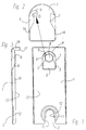
- Figure 1 shows the front view of a side panel 1 with an opening 2 and a recess 3.
- the side panel 1 consists of a preferably flat Sheet metal, which laterally covers a radiator, not shown.
- the Breakthrough 2 is approximately rectangular, the upper limit 4 is rounded off in a semicircle.
- the breakthrough 2 is a punched-out area of the side panel 1.
- the breakthrough 2 is still excess material, which at Punching was left out and has therefore stopped.
- This excess In the case of the side panel 1 according to the invention, material forms two lateral, vertical aligned guide panel parts 6.7, the centering of the tubular Serve connector 8. By correctly setting the two guide panel parts In this way, the connecting element 8 can be located 6, 6 centrally in the opening 2 be aligned.
- connection element 8 can be, for example, connection element 8 for the supply of the Act heating.
- the side panel 1 in the lower region a recess 3.
- the recess 3 is rectangular in the lower region 10 and formed semicircular in the upper region 11.
- the semicircular Area 11 encloses the derivative, not shown here.
- the edge 12 of the semicircular region 11 is in the direction of the inside 13 of the side panel 1 domed.
- FIG. 2 shows an enlarged representation of the opening 2 from FIG. 1 here clearly that the guide panel parts 6.7 in one piece with the edge 14 of the Breakthrough 2 are connected and by punching and a forming process arise.
- the guide panel parts 6.7 remain when punching out of the breakthrough 2 simply cut out so that they are not manufactured and attached separately the side panel 1 must be attached. This has a positive effect on that Manufacturing process and the resulting costs.
- the guide panel parts 6,7 are essentially vertical and practically consist of one angled metal strips. Therefore, they are flexible within certain limits and can for the purpose of aligning or centering the not shown here Connection element are bent or adjusted.
- the side panel part 9 is formed in one piece.
- the side panel part 9 remains like the guide panel parts 6.7 when punching out the opening 2 stand, so that the same advantages as production and costs result as described above.
- the side panel part 9 is hook-shaped, so that the side panel can easily be hung up.
- a predetermined breaking point 15 in the form of a material weakening. This weakening of materials can, for example, in the form of an incision, an injection and / or Perforation is present.
- the predetermined breaking point 15 enables the assembly of the Side panel makes it easier to bend or break off the side panel part 9. In this way, possible defects in the painting are limited exclusively from the side panel part 9, so that the side panel is optically has flawless paintwork.
- An existing notch 19, groove or recess makes it easier to hang up the side panel 1.
- Figure 3 shows a side view of the side panel 1 shown in Figure 1. It is here clearly that the side panel 1 in its edge region 16, 17 each at right angles is bent. These angled edge regions 16, 17 can be connected to the others Elements of the radiator cover, for example a front panel and one Cover plate, be adjusted so that a positive connection with the other components of the cladding is possible.
- the side panel 1 points over it also an upward rectangular, bent end 18 on the other components of the cladding is matched. Fastening the panel can be done for example with the help of special fastening hooks.
Landscapes
- Engineering & Computer Science (AREA)
- Physics & Mathematics (AREA)
- Thermal Sciences (AREA)
- Chemical & Material Sciences (AREA)
- Combustion & Propulsion (AREA)
- Mechanical Engineering (AREA)
- General Engineering & Computer Science (AREA)
- Domestic Hot-Water Supply Systems And Details Of Heating Systems (AREA)
- Casings For Electric Apparatus (AREA)
- Cathode-Ray Tubes And Fluorescent Screens For Display (AREA)
- Details Or Accessories Of Spraying Plant Or Apparatus (AREA)
Description
- Figur 1
- eine Seitenansicht einer erfindungsgemäßen Seitenblende,
- Figur 2
- eine vergrößerte Darstellung des Durchbruchs gemäß Figur 1 mit Seitenblendenteil und
- Figur 3
- eine weitere Seitenansicht der Seitenblende gemäß Figur 1.
- 1
- Seitenblende
- 2
- Durchbruch
- 3
- Ausnehmung
- 4
- Begrenzung
- 5
- Begrenzung
- 6
- Führungsblendenteil
- 7
- Führungsblendenteil
- 8
- Anschlusselement
- 9
- Seitenblendenteil
- 10
- Bereich
- 11
- Bereich
- 12
- Rand
- 13
- Innenseite
- 14
- Rand
- 15
- Sollbruchstelle
- 16
- Randbereich
- 17
- Randbereich
- 18
- Ende
- 19
- Kerbe
Claims (7)
- Seitenblende (1), insbesondere für Plattenheizkörper, mit zumindest einem für Anschlusselemente vorgesehenen Durchbruch (2), welcher eine Zentrierung für die Anschlusselemente (8) aufweist, wobei der zumindest eine Durchbruch (2) teilweise ausgestanzt ist,
dadurch gekennzeichnet, dass ein an die Zentrierung angeformtes Seitenblendenteil (9) im Bereich der aufzunehmenden Anschlusselemente (8) überschüssiges Material stehen bleibt, weiches eine Materialschwächung und/oder Sollbruchstelle aufweist und aus dieser Position durch die Anschlusselemente (8) während der Montage verdrängbar ausgebildet ist. - Seitenblende nach Anspruch 1,
dadurch gekennzeichnet, dass die Zentrierung aus zwei seitlichen und vertikal ausgerichteten Führungsblendenteilen (6) besteht, welche innerhalb des Durchbruchs (2) stehen bleiben. - Seitenblende nach Anspruch 1 oder 2,
dadurch gekennzeichnet, dass das stehengebliebene Seitenblendenteil (9) mit dem Rand (14) des Durchbruchs (2) und/oder der Zentrierung einstückig verbunden ist. - Seitenblende nach einem oder mehreren der Ansprüche 1 - 3,
dadurch gekennzeichnet, dass die Materialschwächung aus einem Einschnitt, einer Einpressung, einer Einkerbung und/oder Perforation gebildet ist. - Seitenblende nach einem oder mehreren der Ansprüche 1 - 4,
dadurch gekennzeichnet, dass die Materialschwächung aus einer Kerbe, einer Nut oder einer Vertiefung im stehengebliebenen Seitenblendenteil (9) besteht. - Seitenblende nach einem oder mehreren Ansprüchen 1 - 5,
dadurch gekennzeichnet, dass mehrere Durchbrüche (2) vorhanden sind, die derart ausgebildet sind. - Seitenblende nach einem oder mehreren Ansprüchen 1 - 6,
dadurch gekennzeichnet, dass die Zentrierung und das Seitenblendenteil (9) aus einem abgewinkeltem Metallstreifen bestehen.
Applications Claiming Priority (2)
| Application Number | Priority Date | Filing Date | Title |
|---|---|---|---|
| DE29919614U | 1999-11-08 | ||
| DE29919614U DE29919614U1 (de) | 1999-11-08 | 1999-11-08 | Seitenblende |
Publications (3)
| Publication Number | Publication Date |
|---|---|
| EP1098144A2 EP1098144A2 (de) | 2001-05-09 |
| EP1098144A3 EP1098144A3 (de) | 2001-10-10 |
| EP1098144B1 true EP1098144B1 (de) | 2003-10-29 |
Family
ID=8081332
Family Applications (1)
| Application Number | Title | Priority Date | Filing Date |
|---|---|---|---|
| EP00120611A Expired - Lifetime EP1098144B1 (de) | 1999-11-08 | 2000-09-21 | Seitenblende |
Country Status (3)
| Country | Link |
|---|---|
| EP (1) | EP1098144B1 (de) |
| AT (1) | ATE253204T1 (de) |
| DE (2) | DE29919614U1 (de) |
Cited By (1)
| Publication number | Priority date | Publication date | Assignee | Title |
|---|---|---|---|---|
| DE202016002405U1 (de) | 2015-12-09 | 2016-04-26 | Wiemann Gmbh | Seitenverkleidung für Plattenheizkörper mit abgestuftem Übergangsabschnitt zwischen Randkanten und stirnseitigen Aufkantungsbereichen |
Families Citing this family (1)
| Publication number | Priority date | Publication date | Assignee | Title |
|---|---|---|---|---|
| DE202014000809U1 (de) * | 2014-01-31 | 2014-03-11 | Ulamo Holding Bv | Seitenblende für einen Heizkörper |
Family Cites Families (2)
| Publication number | Priority date | Publication date | Assignee | Title |
|---|---|---|---|---|
| DE29604834U1 (de) * | 1996-03-15 | 1996-05-09 | Ulamo Beheer B.V., Ulft | Randabdeckung für Flachheizkörper |
| DE29703909U1 (de) * | 1997-03-04 | 1998-07-09 | Sigarth Ab, Hillerstorp | Abdeckvorrichtung für Heizkörper mit auswechselbaren Eckteilen |
-
1999
- 1999-11-08 DE DE29919614U patent/DE29919614U1/de not_active Expired - Lifetime
-
2000
- 2000-09-21 AT AT00120611T patent/ATE253204T1/de not_active IP Right Cessation
- 2000-09-21 DE DE50004235T patent/DE50004235D1/de not_active Expired - Fee Related
- 2000-09-21 EP EP00120611A patent/EP1098144B1/de not_active Expired - Lifetime
Cited By (2)
| Publication number | Priority date | Publication date | Assignee | Title |
|---|---|---|---|---|
| DE202016002405U1 (de) | 2015-12-09 | 2016-04-26 | Wiemann Gmbh | Seitenverkleidung für Plattenheizkörper mit abgestuftem Übergangsabschnitt zwischen Randkanten und stirnseitigen Aufkantungsbereichen |
| DE102015015873A1 (de) | 2015-12-09 | 2017-06-14 | Wiemann Gmbh | Seitenverkleidung für Plattenheizkörper |
Also Published As
| Publication number | Publication date |
|---|---|
| EP1098144A2 (de) | 2001-05-09 |
| ATE253204T1 (de) | 2003-11-15 |
| EP1098144A3 (de) | 2001-10-10 |
| DE29919614U1 (de) | 2000-02-03 |
| DE50004235D1 (de) | 2003-12-04 |
Similar Documents
| Publication | Publication Date | Title |
|---|---|---|
| EP2192352B1 (de) | Kochfeld sowie Verfahren zur Herstellung eines Kochfelds | |
| EP1098144B1 (de) | Seitenblende | |
| EP0602456A1 (de) | Rohrschelle | |
| EP2378209A2 (de) | Dunstabzugshaube | |
| DE29604834U1 (de) | Randabdeckung für Flachheizkörper | |
| DE29500353U1 (de) | Vorrichtung zur höhenverstellbaren kraftschlüssigen Befestigung, insbesondere zum Abhängen von Holzunterkonstruktionen für Decken | |
| DE4323199A1 (de) | Standkonsole für Heizkörper | |
| DE29511988U1 (de) | Vorrichtung zur Befestigung einer Frontplatte an einem Heizkörper | |
| DE3226791A1 (de) | Stuetz- und befestigungselement fuer die wandseitige befestigung einer badewanne, insbesondere einer kunststoffbadewanne | |
| EP0271075B1 (de) | Anschlussprofil für Wand- und Deckenpaneele | |
| DE4401128C2 (de) | Wandkonsole für die Montage und Demontage eines Heizkörpers | |
| DE19737893B4 (de) | Installationskanal mit Abdeckung und Potentialausgleichsklammer für den Potentialausgleich zwischen diesen | |
| DE202007013609U1 (de) | Seitenblende für einen Heizkörper | |
| DE4334704C1 (de) | Vorrichtung zur Befestigung einer Abdeckplatte an einem Plattenheizkörper | |
| DE3525967A1 (de) | Halterung fuer mit aufhaengelaschen versehene heizkoerper | |
| DE202021104587U1 (de) | Verbinderhalterung zum Verbinden eines Abdeckelementsund eines Verkleidungselements mit einem Fensterrahmen und solch eine Verbinderhalterung umfassendesDachfenster | |
| DE202015104529U1 (de) | Pflanzenkastenhalter | |
| DE29712603U1 (de) | Einbauleuchte | |
| DE20019236U1 (de) | Clip-in-Aufhängesystem für Metallpaneele | |
| EP1400759B1 (de) | Befestigungsmittel | |
| EP2902715B1 (de) | Seitenblende für einen Heizkörper | |
| EP0718549B1 (de) | Befestigungsvorrichtung | |
| DE69005007T2 (de) | Möbelscharnier. | |
| EP1403442B2 (de) | Markise mit Infrarotstrahler und/oder Lautsprecher | |
| DE102023116147A1 (de) | Überlaufgarnitur, Verfahren zur Herstellung einer Überlaufgarnitur und Badewanne |
Legal Events
| Date | Code | Title | Description |
|---|---|---|---|
| PUAI | Public reference made under article 153(3) epc to a published international application that has entered the european phase |
Free format text: ORIGINAL CODE: 0009012 |
|
| AK | Designated contracting states |
Kind code of ref document: A2 Designated state(s): AT BE CH CY DE DK ES FI FR GB GR IE IT LI LU MC NL PT SE |
|
| AX | Request for extension of the european patent |
Free format text: AL;LT;LV;MK;RO;SI |
|
| PUAL | Search report despatched |
Free format text: ORIGINAL CODE: 0009013 |
|
| AK | Designated contracting states |
Kind code of ref document: A3 Designated state(s): AT BE CH CY DE DK ES FI FR GB GR IE IT LI LU MC NL PT SE |
|
| AX | Request for extension of the european patent |
Free format text: AL;LT;LV;MK;RO;SI |
|
| 17P | Request for examination filed |
Effective date: 20011109 |
|
| AKX | Designation fees paid |
Free format text: AT BE CH CY DE DK ES FI FR GB GR IE IT LI LU MC NL PT SE |
|
| 17Q | First examination report despatched |
Effective date: 20021126 |
|
| GRAH | Despatch of communication of intention to grant a patent |
Free format text: ORIGINAL CODE: EPIDOS IGRA |
|
| GRAS | Grant fee paid |
Free format text: ORIGINAL CODE: EPIDOSNIGR3 |
|
| GRAA | (expected) grant |
Free format text: ORIGINAL CODE: 0009210 |
|
| AK | Designated contracting states |
Kind code of ref document: B1 Designated state(s): AT BE CH CY DE DK ES FI FR GB GR IE IT LI LU MC NL PT SE |
|
| PG25 | Lapsed in a contracting state [announced via postgrant information from national office to epo] |
Ref country code: IE Free format text: LAPSE BECAUSE OF FAILURE TO SUBMIT A TRANSLATION OF THE DESCRIPTION OR TO PAY THE FEE WITHIN THE PRESCRIBED TIME-LIMIT Effective date: 20031029 Ref country code: FI Free format text: LAPSE BECAUSE OF FAILURE TO SUBMIT A TRANSLATION OF THE DESCRIPTION OR TO PAY THE FEE WITHIN THE PRESCRIBED TIME-LIMIT Effective date: 20031029 Ref country code: IT Free format text: LAPSE BECAUSE OF FAILURE TO SUBMIT A TRANSLATION OF THE DESCRIPTION OR TO PAY THE FEE WITHIN THE PRESCRIBED TIME-LIMIT;WARNING: LAPSES OF ITALIAN PATENTS WITH EFFECTIVE DATE BEFORE 2007 MAY HAVE OCCURRED AT ANY TIME BEFORE 2007. THE CORRECT EFFECTIVE DATE MAY BE DIFFERENT FROM THE ONE RECORDED. Effective date: 20031029 Ref country code: CY Free format text: LAPSE BECAUSE OF FAILURE TO SUBMIT A TRANSLATION OF THE DESCRIPTION OR TO PAY THE FEE WITHIN THE PRESCRIBED TIME-LIMIT Effective date: 20031029 |
|
| REG | Reference to a national code |
Ref country code: GB Ref legal event code: FG4D Free format text: NOT ENGLISH |
|
| REG | Reference to a national code |
Ref country code: CH Ref legal event code: EP |
|
| REG | Reference to a national code |
Ref country code: IE Ref legal event code: FG4D Free format text: GERMAN |
|
| REF | Corresponds to: |
Ref document number: 50004235 Country of ref document: DE Date of ref document: 20031204 Kind code of ref document: P |
|
| GBT | Gb: translation of ep patent filed (gb section 77(6)(a)/1977) |
Effective date: 20031217 |
|
| PG25 | Lapsed in a contracting state [announced via postgrant information from national office to epo] |
Ref country code: GR Free format text: LAPSE BECAUSE OF FAILURE TO SUBMIT A TRANSLATION OF THE DESCRIPTION OR TO PAY THE FEE WITHIN THE PRESCRIBED TIME-LIMIT Effective date: 20040129 Ref country code: DK Free format text: LAPSE BECAUSE OF FAILURE TO SUBMIT A TRANSLATION OF THE DESCRIPTION OR TO PAY THE FEE WITHIN THE PRESCRIBED TIME-LIMIT Effective date: 20040129 Ref country code: SE Free format text: LAPSE BECAUSE OF FAILURE TO SUBMIT A TRANSLATION OF THE DESCRIPTION OR TO PAY THE FEE WITHIN THE PRESCRIBED TIME-LIMIT Effective date: 20040129 |
|
| PG25 | Lapsed in a contracting state [announced via postgrant information from national office to epo] |
Ref country code: ES Free format text: LAPSE BECAUSE OF FAILURE TO SUBMIT A TRANSLATION OF THE DESCRIPTION OR TO PAY THE FEE WITHIN THE PRESCRIBED TIME-LIMIT Effective date: 20040209 |
|
| REG | Reference to a national code |
Ref country code: IE Ref legal event code: FD4D |
|
| ET | Fr: translation filed | ||
| PLBE | No opposition filed within time limit |
Free format text: ORIGINAL CODE: 0009261 |
|
| STAA | Information on the status of an ep patent application or granted ep patent |
Free format text: STATUS: NO OPPOSITION FILED WITHIN TIME LIMIT |
|
| PG25 | Lapsed in a contracting state [announced via postgrant information from national office to epo] |
Ref country code: LU Free format text: LAPSE BECAUSE OF NON-PAYMENT OF DUE FEES Effective date: 20040921 Ref country code: AT Free format text: LAPSE BECAUSE OF NON-PAYMENT OF DUE FEES Effective date: 20040921 |
|
| PG25 | Lapsed in a contracting state [announced via postgrant information from national office to epo] |
Ref country code: BE Free format text: LAPSE BECAUSE OF NON-PAYMENT OF DUE FEES Effective date: 20040930 Ref country code: LI Free format text: LAPSE BECAUSE OF NON-PAYMENT OF DUE FEES Effective date: 20040930 Ref country code: CH Free format text: LAPSE BECAUSE OF NON-PAYMENT OF DUE FEES Effective date: 20040930 Ref country code: MC Free format text: LAPSE BECAUSE OF NON-PAYMENT OF DUE FEES Effective date: 20040930 |
|
| 26N | No opposition filed |
Effective date: 20040730 |
|
| BERE | Be: lapsed |
Owner name: *ULAMO BEHEER B.V. Effective date: 20040930 |
|
| REG | Reference to a national code |
Ref country code: CH Ref legal event code: PL |
|
| PGFP | Annual fee paid to national office [announced via postgrant information from national office to epo] |
Ref country code: FR Payment date: 20060922 Year of fee payment: 7 Ref country code: GB Payment date: 20060922 Year of fee payment: 7 |
|
| PGFP | Annual fee paid to national office [announced via postgrant information from national office to epo] |
Ref country code: DE Payment date: 20061130 Year of fee payment: 7 |
|
| BERE | Be: lapsed |
Owner name: *ULAMO BEHEER B.V. Effective date: 20040930 |
|
| PG25 | Lapsed in a contracting state [announced via postgrant information from national office to epo] |
Ref country code: PT Free format text: LAPSE BECAUSE OF NON-PAYMENT OF DUE FEES Effective date: 20040329 |
|
| GBPC | Gb: european patent ceased through non-payment of renewal fee |
Effective date: 20070921 |
|
| PG25 | Lapsed in a contracting state [announced via postgrant information from national office to epo] |
Ref country code: DE Free format text: LAPSE BECAUSE OF NON-PAYMENT OF DUE FEES Effective date: 20080401 |
|
| REG | Reference to a national code |
Ref country code: FR Ref legal event code: ST Effective date: 20080531 |
|
| PG25 | Lapsed in a contracting state [announced via postgrant information from national office to epo] |
Ref country code: FR Free format text: LAPSE BECAUSE OF NON-PAYMENT OF DUE FEES Effective date: 20071001 |
|
| PG25 | Lapsed in a contracting state [announced via postgrant information from national office to epo] |
Ref country code: GB Free format text: LAPSE BECAUSE OF NON-PAYMENT OF DUE FEES Effective date: 20070921 |
|
| PGFP | Annual fee paid to national office [announced via postgrant information from national office to epo] |
Ref country code: NL Payment date: 20130920 Year of fee payment: 14 |
|
| PG25 | Lapsed in a contracting state [announced via postgrant information from national office to epo] |
Ref country code: NL Free format text: LAPSE BECAUSE OF NON-PAYMENT OF DUE FEES Effective date: 20150401 |