EP1098112B1 - Gangwahleinrichtung - Google Patents
Gangwahleinrichtung Download PDFInfo
- Publication number
- EP1098112B1 EP1098112B1 EP00123019A EP00123019A EP1098112B1 EP 1098112 B1 EP1098112 B1 EP 1098112B1 EP 00123019 A EP00123019 A EP 00123019A EP 00123019 A EP00123019 A EP 00123019A EP 1098112 B1 EP1098112 B1 EP 1098112B1
- Authority
- EP
- European Patent Office
- Prior art keywords
- display
- control element
- operator control
- shift position
- gear speed
- Prior art date
- Legal status (The legal status is an assumption and is not a legal conclusion. Google has not performed a legal analysis and makes no representation as to the accuracy of the status listed.)
- Expired - Lifetime
Links
Images
Classifications
-
- F—MECHANICAL ENGINEERING; LIGHTING; HEATING; WEAPONS; BLASTING
- F16—ENGINEERING ELEMENTS AND UNITS; GENERAL MEASURES FOR PRODUCING AND MAINTAINING EFFECTIVE FUNCTIONING OF MACHINES OR INSTALLATIONS; THERMAL INSULATION IN GENERAL
- F16H—GEARING
- F16H59/00—Control inputs to control units of change-speed- or reversing-gearings for conveying rotary motion
- F16H59/02—Selector apparatus
- F16H59/08—Range selector apparatus
- F16H59/12—Range selector apparatus comprising push button devices
-
- F—MECHANICAL ENGINEERING; LIGHTING; HEATING; WEAPONS; BLASTING
- F16—ENGINEERING ELEMENTS AND UNITS; GENERAL MEASURES FOR PRODUCING AND MAINTAINING EFFECTIVE FUNCTIONING OF MACHINES OR INSTALLATIONS; THERMAL INSULATION IN GENERAL
- F16H—GEARING
- F16H59/00—Control inputs to control units of change-speed- or reversing-gearings for conveying rotary motion
- F16H59/02—Selector apparatus
- F16H59/08—Range selector apparatus
-
- B—PERFORMING OPERATIONS; TRANSPORTING
- B60—VEHICLES IN GENERAL
- B60K—ARRANGEMENT OR MOUNTING OF PROPULSION UNITS OR OF TRANSMISSIONS IN VEHICLES; ARRANGEMENT OR MOUNTING OF PLURAL DIVERSE PRIME-MOVERS IN VEHICLES; AUXILIARY DRIVES FOR VEHICLES; INSTRUMENTATION OR DASHBOARDS FOR VEHICLES; ARRANGEMENTS IN CONNECTION WITH COOLING, AIR INTAKE, GAS EXHAUST OR FUEL SUPPLY OF PROPULSION UNITS IN VEHICLES
- B60K20/00—Arrangement or mounting of change-speed gearing control devices in vehicles
- B60K20/02—Arrangement or mounting of change-speed gearing control devices in vehicles of initiating means
- B60K20/08—Dashboard means
-
- F—MECHANICAL ENGINEERING; LIGHTING; HEATING; WEAPONS; BLASTING
- F16—ENGINEERING ELEMENTS AND UNITS; GENERAL MEASURES FOR PRODUCING AND MAINTAINING EFFECTIVE FUNCTIONING OF MACHINES OR INSTALLATIONS; THERMAL INSULATION IN GENERAL
- F16H—GEARING
- F16H63/00—Control outputs from the control unit to change-speed- or reversing-gearings for conveying rotary motion or to other devices than the final output mechanism
- F16H63/40—Control outputs from the control unit to change-speed- or reversing-gearings for conveying rotary motion or to other devices than the final output mechanism comprising signals other than signals for actuating the final output mechanisms
- F16H63/42—Ratio indicator devices
- F16H2063/423—Range indicators for automatic transmissions, e.g. showing selected range or mode
Definitions
- the invention relates to a gear selector switch for setting a Shift position or a gear in an automatic transmission of a Vehicle.
- Gear selector switches have long been known in the form of mechanical shifter. But they are also already e.g. from Voith Antriebstechnik in D-89510 Heidenheim in the form of an electromechanical module as a key switch been realized in each shift position of the automatic transmission latching switch is assigned, the assignment of each switch to a certain adjustable in the automatic transmission gear a corresponding label is displayed on or at each switch. In a transmission with, for example, six adjustable switch positions Therefore, such an assembly has six switches, resulting in a considerable volume of construction for this assembly. So can the front space requirements z. B. at about 120 x 20 mm, if - like common - all six switches are arranged in a row.
- the gear selector switch is used to set a Switching position or a gear only with a single control element equipped, this one control is assigned a display and with this one control each in the automatic transmission existing shift position or each gear is adjustable.
- On the display is numerically, alphanumerically or by appropriate symbolism currently set shift position or the currently set gear can be displayed.
- the one control element, the one lift button, a shift mat button or a Rocker switch is, and the display are with an electronic Circuitry connected to an arranged in the vehicle Data bus is connected and triggered by the control Issue control commands via the data bus to the transmission.
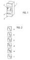
- Figure 1 shows the housing 1 of a gear selector switch according to the invention.
- the housing 1 can be embedded in the dashboard of a vehicle and be completed on the front with a panel 2.
- a as Button trained control element 3 and a control this third assigned display 4, wherein the display 4 in LCD technology or can be implemented in any other suitable technology.
- On the Display 4 are in accordance with the operation of the control element 3 the respective shift position or the selected gear in the automatic Transmission of the vehicle preferably displayed in alphanumeric form.
- These various displays a b, c, d, e, f are exemplary in FIG. 2 shown. You can according to the design and control of the automatic transmission with the control element 3 selected sequentially and be adjusted.
- control element 3 and the Display 4 with an electronic, not shown in the figures Circuitry connected to an arranged in the vehicle Data bus is connected and triggered by the control element 3 Issue control commands via the data bus to the transmission. That's constructive Operating element 3 as a lift button, as a switch mat button or as Rocker switch formed. It is especially advantageous that Operating element 3 and the display 4 - as shown in the figure 1 - in one single unit, d. H. to arrange in a single housing 1.
- the association between the operation of the Operating element 3 and the choice of a switching position or the setting a gear in the automatic transmission and the type of display a, b, c, d, e, f of the currently selected shift position or of the currently set one Ganges on the display 4 programmatically stored in a memory which is part of the circuit arrangement with which the Operating element 3 and the display 4 are connected.
- Display 4 for improving the readability of its displays a b, c, d, e, f and If necessary, the control element 3 for the realization of a search help illuminate dark surroundings with one or more light emitting diodes and for the light distribution optionally provide a light guide.
- Light emission can be provided to a single switching position of the highlight other switch positions. So z. B. the neutral Switched position to be illuminated in red. In this case, when reaching a specific shift position for the driver of the color change of Display 4 a well perceptible signal effect.
Landscapes
- Engineering & Computer Science (AREA)
- General Engineering & Computer Science (AREA)
- Mechanical Engineering (AREA)
- Arrangement And Mounting Of Devices That Control Transmission Of Motive Force (AREA)
- Control Of Transmission Device (AREA)
- Arrangement Or Mounting Of Control Devices For Change-Speed Gearing (AREA)
Applications Claiming Priority (2)
| Application Number | Priority Date | Filing Date | Title |
|---|---|---|---|
| DE29919274U DE29919274U1 (de) | 1999-11-03 | 1999-11-03 | Gangwahlschalter |
| DE29919274U | 1999-11-03 |
Publications (3)
| Publication Number | Publication Date |
|---|---|
| EP1098112A2 EP1098112A2 (de) | 2001-05-09 |
| EP1098112A3 EP1098112A3 (de) | 2003-04-16 |
| EP1098112B1 true EP1098112B1 (de) | 2005-06-22 |
Family
ID=8081090
Family Applications (1)
| Application Number | Title | Priority Date | Filing Date |
|---|---|---|---|
| EP00123019A Expired - Lifetime EP1098112B1 (de) | 1999-11-03 | 2000-10-24 | Gangwahleinrichtung |
Country Status (3)
| Country | Link |
|---|---|
| EP (1) | EP1098112B1 (pl) |
| DE (2) | DE29919274U1 (pl) |
| PL (1) | PL197644B1 (pl) |
Families Citing this family (3)
| Publication number | Priority date | Publication date | Assignee | Title |
|---|---|---|---|---|
| DE20020621U1 (de) | 2000-12-04 | 2001-03-08 | Voith Turbo GmbH & Co. KG, 89522 Heidenheim | Vorwahleinrichtung, insbesondere Tastenschalter |
| DE10137902A1 (de) | 2001-01-29 | 2002-08-22 | Voith Turbo Kg | Verfahren zur Erhöhung der Fahrsicherheit beim Betrieb von Fahrzeugen mit integriertem Automatgetriebe durch Signalisierung der Akzeptanz einer gewünschten Fahrzustandsänderung und System zur Steuerung einer Getriebebaueinheit |
| DE10241014A1 (de) * | 2002-09-05 | 2004-03-11 | Zf Friedrichshafen Ag | Verfahren und Einrichtung zur Ansteuerung eines Automatgetriebes mit elektronischer Schaltung |
Family Cites Families (3)
| Publication number | Priority date | Publication date | Assignee | Title |
|---|---|---|---|---|
| FR2600285B1 (fr) * | 1986-06-20 | 1988-10-07 | Renault | Dispositif de commande electromecanique de boite de vitesses automatique |
| GB8906918D0 (en) * | 1989-03-28 | 1989-05-10 | Eaton Corp | Method for upshifting a compound semi-blocked splitter type automatic mechanical transmission |
| DE19509472A1 (de) * | 1995-03-16 | 1996-09-19 | Ringe Joachim | Plusminus-Tasten-Gangschaltung |
-
1999
- 1999-11-03 DE DE29919274U patent/DE29919274U1/de not_active Expired - Lifetime
-
2000
- 2000-10-24 EP EP00123019A patent/EP1098112B1/de not_active Expired - Lifetime
- 2000-10-24 DE DE50010597T patent/DE50010597D1/de not_active Expired - Lifetime
- 2000-11-02 PL PL343657A patent/PL197644B1/pl unknown
Also Published As
| Publication number | Publication date |
|---|---|
| EP1098112A2 (de) | 2001-05-09 |
| PL343657A1 (en) | 2001-05-07 |
| EP1098112A3 (de) | 2003-04-16 |
| PL197644B1 (pl) | 2008-04-30 |
| DE29919274U1 (de) | 2000-01-05 |
| DE50010597D1 (de) | 2005-07-28 |
Similar Documents
| Publication | Publication Date | Title |
|---|---|---|
| EP1338831B1 (de) | Getriebeschalteinrichtung | |
| DE3832971C2 (pl) | ||
| DE19916924A1 (de) | Kraftfahrzeug mit einer Wähleinrichtung | |
| WO2008074375A1 (de) | Schaltungsbedienelement für ein getriebe eines kraftfahrzeugs mit elektronisch gesteuerter schaltung | |
| DE19828039B4 (de) | Bedienvorrichtung | |
| EP0771680A1 (de) | Bediengerät | |
| DE19945775A1 (de) | Leuchtenanordnung für ein Fahrzeug | |
| DE102007024150B4 (de) | Multifunktionsbedienvorrichtung und Verfahren zum Steuern einer Multifunktionsbedienvorrichtung | |
| DE102008001884B4 (de) | Betätigungseinrichtung mit Lichtleiterbündel | |
| EP1098112B1 (de) | Gangwahleinrichtung | |
| DE202007010136U1 (de) | Stellrad | |
| DE19529207C2 (de) | Schaltstellungsanzeige | |
| EP1215555B1 (de) | Steller insbesondere eines Kraftfahrzeuges mit einer positionsveränderbaren Marke | |
| DE3939030A1 (de) | Schaltstellungsanzeige fuer schalt- oder waehlhebel | |
| DE102005048875B4 (de) | Schalteinheit für ein elektronisch geschaltetes Getriebe eines Kraftfahrzeugs | |
| EP1167831B1 (de) | Bedienungsvorrichtung zur Schaltsteuerung eines Kraftfahrzeuggetriebes | |
| DE102004062509A1 (de) | Betätigungseinheit für eine Fahrzeugkomponente | |
| EP1380773B1 (de) | Vorrichtung und Verfahren zur Steuerung eines automatisierten Schaltgetriebes eines Kraftfahrzeuges | |
| DE10048577B4 (de) | Schalteinrichtung zur Steuerung eines Automatik-Getriebes und Verfahren zur Steuerung der visuellen Anzeigen der Schalteinrichtung | |
| EP2113931A2 (de) | Handbedienung zur Bedienung eines elektromotorischen Möbelantriebs | |
| DE10211968A1 (de) | Anzeigeeinheit für eine Wählhebelschaltung | |
| DE102006008816B4 (de) | Schalteinrichtung für ein elektronisch geschaltetes Getriebe eines Kraftfahrzeugs | |
| EP2980779A1 (de) | Anzeigeeinheit mit Symbolanzeige und Schaltfunktion | |
| EP3721119B1 (de) | Vorrichtung zur fahrstufenauswahl | |
| DE10309509A1 (de) | Anzeigeeinrichtung zur Darstellung verschiedener Schaltzustände |
Legal Events
| Date | Code | Title | Description |
|---|---|---|---|
| PUAI | Public reference made under article 153(3) epc to a published international application that has entered the european phase |
Free format text: ORIGINAL CODE: 0009012 |
|
| AK | Designated contracting states |
Kind code of ref document: A2 Designated state(s): AT BE CH CY DE DK ES FI FR GB GR IE IT LI LU MC NL PT SE |
|
| AX | Request for extension of the european patent |
Free format text: AL;LT;LV;MK;RO;SI |
|
| RAP1 | Party data changed (applicant data changed or rights of an application transferred) |
Owner name: SIEMENS AKTIENGESELLSCHAFT |
|
| PUAL | Search report despatched |
Free format text: ORIGINAL CODE: 0009013 |
|
| AK | Designated contracting states |
Designated state(s): AT BE CH CY DE DK ES FI FR GB GR IE IT LI LU MC NL PT SE |
|
| AX | Request for extension of the european patent |
Extension state: AL LT LV MK RO SI |
|
| AKX | Designation fees paid | ||
| 17P | Request for examination filed |
Effective date: 20031202 |
|
| RBV | Designated contracting states (corrected) |
Designated state(s): DE FR GB IT |
|
| REG | Reference to a national code |
Ref country code: DE Ref legal event code: 8566 |
|
| 17Q | First examination report despatched |
Effective date: 20040202 |
|
| GRAP | Despatch of communication of intention to grant a patent |
Free format text: ORIGINAL CODE: EPIDOSNIGR1 |
|
| GRAS | Grant fee paid |
Free format text: ORIGINAL CODE: EPIDOSNIGR3 |
|
| GRAA | (expected) grant |
Free format text: ORIGINAL CODE: 0009210 |
|
| AK | Designated contracting states |
Kind code of ref document: B1 Designated state(s): DE FR GB IT |
|
| REG | Reference to a national code |
Ref country code: GB Ref legal event code: FG4D Free format text: NOT ENGLISH |
|
| REF | Corresponds to: |
Ref document number: 50010597 Country of ref document: DE Date of ref document: 20050728 Kind code of ref document: P |
|
| GBT | Gb: translation of ep patent filed (gb section 77(6)(a)/1977) |
Effective date: 20050725 |
|
| ET | Fr: translation filed | ||
| PLBE | No opposition filed within time limit |
Free format text: ORIGINAL CODE: 0009261 |
|
| STAA | Information on the status of an ep patent application or granted ep patent |
Free format text: STATUS: NO OPPOSITION FILED WITHIN TIME LIMIT |
|
| 26N | No opposition filed |
Effective date: 20060323 |
|
| REG | Reference to a national code |
Ref country code: FR Ref legal event code: TP |
|
| REG | Reference to a national code |
Ref country code: GB Ref legal event code: 732E Free format text: REGISTERED BETWEEN 20110825 AND 20110831 |
|
| PGFP | Annual fee paid to national office [announced via postgrant information from national office to epo] |
Ref country code: FR Payment date: 20121031 Year of fee payment: 13 |
|
| PGFP | Annual fee paid to national office [announced via postgrant information from national office to epo] |
Ref country code: IT Payment date: 20121026 Year of fee payment: 13 |
|
| REG | Reference to a national code |
Ref country code: FR Ref legal event code: ST Effective date: 20140630 |
|
| PG25 | Lapsed in a contracting state [announced via postgrant information from national office to epo] |
Ref country code: IT Free format text: LAPSE BECAUSE OF NON-PAYMENT OF DUE FEES Effective date: 20131024 Ref country code: FR Free format text: LAPSE BECAUSE OF NON-PAYMENT OF DUE FEES Effective date: 20131031 |
|
| PGFP | Annual fee paid to national office [announced via postgrant information from national office to epo] |
Ref country code: GB Payment date: 20141021 Year of fee payment: 15 |
|
| REG | Reference to a national code |
Ref country code: DE Ref legal event code: R084 Ref document number: 50010597 Country of ref document: DE |
|
| GBPC | Gb: european patent ceased through non-payment of renewal fee |
Effective date: 20151024 |
|
| PG25 | Lapsed in a contracting state [announced via postgrant information from national office to epo] |
Ref country code: GB Free format text: LAPSE BECAUSE OF NON-PAYMENT OF DUE FEES Effective date: 20151024 |
|
| PGFP | Annual fee paid to national office [announced via postgrant information from national office to epo] |
Ref country code: DE Payment date: 20171031 Year of fee payment: 18 |
|
| REG | Reference to a national code |
Ref country code: DE Ref legal event code: R119 Ref document number: 50010597 Country of ref document: DE |
|
| PG25 | Lapsed in a contracting state [announced via postgrant information from national office to epo] |
Ref country code: DE Free format text: LAPSE BECAUSE OF NON-PAYMENT OF DUE FEES Effective date: 20190501 |