EP1098112B1 - Gear selection device - Google Patents
Gear selection device Download PDFInfo
- Publication number
- EP1098112B1 EP1098112B1 EP00123019A EP00123019A EP1098112B1 EP 1098112 B1 EP1098112 B1 EP 1098112B1 EP 00123019 A EP00123019 A EP 00123019A EP 00123019 A EP00123019 A EP 00123019A EP 1098112 B1 EP1098112 B1 EP 1098112B1
- Authority
- EP
- European Patent Office
- Prior art keywords
- display
- control element
- operator control
- shift position
- gear speed
- Prior art date
- Legal status (The legal status is an assumption and is not a legal conclusion. Google has not performed a legal analysis and makes no representation as to the accuracy of the status listed.)
- Expired - Lifetime
Links
Images
Classifications
-
- F—MECHANICAL ENGINEERING; LIGHTING; HEATING; WEAPONS; BLASTING
- F16—ENGINEERING ELEMENTS AND UNITS; GENERAL MEASURES FOR PRODUCING AND MAINTAINING EFFECTIVE FUNCTIONING OF MACHINES OR INSTALLATIONS; THERMAL INSULATION IN GENERAL
- F16H—GEARING
- F16H59/00—Control inputs to control units of change-speed-, or reversing-gearings for conveying rotary motion
- F16H59/02—Selector apparatus
- F16H59/08—Range selector apparatus
- F16H59/12—Range selector apparatus comprising push button devices
-
- F—MECHANICAL ENGINEERING; LIGHTING; HEATING; WEAPONS; BLASTING
- F16—ENGINEERING ELEMENTS AND UNITS; GENERAL MEASURES FOR PRODUCING AND MAINTAINING EFFECTIVE FUNCTIONING OF MACHINES OR INSTALLATIONS; THERMAL INSULATION IN GENERAL
- F16H—GEARING
- F16H59/00—Control inputs to control units of change-speed-, or reversing-gearings for conveying rotary motion
- F16H59/02—Selector apparatus
- F16H59/08—Range selector apparatus
-
- B—PERFORMING OPERATIONS; TRANSPORTING
- B60—VEHICLES IN GENERAL
- B60K—ARRANGEMENT OR MOUNTING OF PROPULSION UNITS OR OF TRANSMISSIONS IN VEHICLES; ARRANGEMENT OR MOUNTING OF PLURAL DIVERSE PRIME-MOVERS IN VEHICLES; AUXILIARY DRIVES FOR VEHICLES; INSTRUMENTATION OR DASHBOARDS FOR VEHICLES; ARRANGEMENTS IN CONNECTION WITH COOLING, AIR INTAKE, GAS EXHAUST OR FUEL SUPPLY OF PROPULSION UNITS IN VEHICLES
- B60K20/00—Arrangement or mounting of change-speed gearing control devices in vehicles
- B60K20/02—Arrangement or mounting of change-speed gearing control devices in vehicles of initiating means
- B60K20/08—Dashboard means
-
- F—MECHANICAL ENGINEERING; LIGHTING; HEATING; WEAPONS; BLASTING
- F16—ENGINEERING ELEMENTS AND UNITS; GENERAL MEASURES FOR PRODUCING AND MAINTAINING EFFECTIVE FUNCTIONING OF MACHINES OR INSTALLATIONS; THERMAL INSULATION IN GENERAL
- F16H—GEARING
- F16H63/00—Control outputs from the control unit to change-speed- or reversing-gearings for conveying rotary motion or to other devices than the final output mechanism
- F16H63/40—Control outputs from the control unit to change-speed- or reversing-gearings for conveying rotary motion or to other devices than the final output mechanism comprising signals other than signals for actuating the final output mechanisms
- F16H63/42—Ratio indicator devices
- F16H2063/423—Range indicators for automatic transmissions, e.g. showing selected range or mode
Definitions
- the invention relates to a gear selector switch for setting a Shift position or a gear in an automatic transmission of a Vehicle.
- Gear selector switches have long been known in the form of mechanical shifter. But they are also already e.g. from Voith Antriebstechnik in D-89510 Heidenheim in the form of an electromechanical module as a key switch been realized in each shift position of the automatic transmission latching switch is assigned, the assignment of each switch to a certain adjustable in the automatic transmission gear a corresponding label is displayed on or at each switch. In a transmission with, for example, six adjustable switch positions Therefore, such an assembly has six switches, resulting in a considerable volume of construction for this assembly. So can the front space requirements z. B. at about 120 x 20 mm, if - like common - all six switches are arranged in a row.
- the gear selector switch is used to set a Switching position or a gear only with a single control element equipped, this one control is assigned a display and with this one control each in the automatic transmission existing shift position or each gear is adjustable.
- On the display is numerically, alphanumerically or by appropriate symbolism currently set shift position or the currently set gear can be displayed.
- the one control element, the one lift button, a shift mat button or a Rocker switch is, and the display are with an electronic Circuitry connected to an arranged in the vehicle Data bus is connected and triggered by the control Issue control commands via the data bus to the transmission.
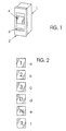
- Figure 1 shows the housing 1 of a gear selector switch according to the invention.
- the housing 1 can be embedded in the dashboard of a vehicle and be completed on the front with a panel 2.
- a as Button trained control element 3 and a control this third assigned display 4, wherein the display 4 in LCD technology or can be implemented in any other suitable technology.
- On the Display 4 are in accordance with the operation of the control element 3 the respective shift position or the selected gear in the automatic Transmission of the vehicle preferably displayed in alphanumeric form.
- These various displays a b, c, d, e, f are exemplary in FIG. 2 shown. You can according to the design and control of the automatic transmission with the control element 3 selected sequentially and be adjusted.
- control element 3 and the Display 4 with an electronic, not shown in the figures Circuitry connected to an arranged in the vehicle Data bus is connected and triggered by the control element 3 Issue control commands via the data bus to the transmission. That's constructive Operating element 3 as a lift button, as a switch mat button or as Rocker switch formed. It is especially advantageous that Operating element 3 and the display 4 - as shown in the figure 1 - in one single unit, d. H. to arrange in a single housing 1.
- the association between the operation of the Operating element 3 and the choice of a switching position or the setting a gear in the automatic transmission and the type of display a, b, c, d, e, f of the currently selected shift position or of the currently set one Ganges on the display 4 programmatically stored in a memory which is part of the circuit arrangement with which the Operating element 3 and the display 4 are connected.
- Display 4 for improving the readability of its displays a b, c, d, e, f and If necessary, the control element 3 for the realization of a search help illuminate dark surroundings with one or more light emitting diodes and for the light distribution optionally provide a light guide.
- Light emission can be provided to a single switching position of the highlight other switch positions. So z. B. the neutral Switched position to be illuminated in red. In this case, when reaching a specific shift position for the driver of the color change of Display 4 a well perceptible signal effect.
Landscapes
- Engineering & Computer Science (AREA)
- General Engineering & Computer Science (AREA)
- Mechanical Engineering (AREA)
- Arrangement And Mounting Of Devices That Control Transmission Of Motive Force (AREA)
- Control Of Transmission Device (AREA)
- Arrangement Or Mounting Of Control Devices For Change-Speed Gearing (AREA)
Description
Die Erfindung betrifft einen Gangwahlschalter zum Einstellen einer Schaltstellung bzw. eines Ganges bei einem automatischen Getriebe eines Fahrzeugs.The invention relates to a gear selector switch for setting a Shift position or a gear in an automatic transmission of a Vehicle.
Gangwahlschalter sind seit langem in Form mechanischer Schalthebel bekannt. Sie sind aber auch schon z.B. von der Fa. Voith Antriebstechnik in D-89510 Heidenheim in Form einer elektromechanischen Baugruppe als Tastenschalter realisiert worden, bei der jeder Schaltstellung des automatischen Getriebes ein rastender Schalter zugeordnet ist, wobei die Zuordnung jedes Schalters zu einem bestimmten bei dem automatischen Getriebe einstellbaren Gang durch eine entsprechende Beschriftung auf oder an jedem Schalter angezeigt wird. Bei einem Getriebe mit beispielsweise sechs einstellbaren Schaltstellungen bzw. Gängen besitzt eine solche Baugruppe daher dann sechs Schalter, wodurch sich für diese Baugruppe ein beträchtliches Bauvolumen ergibt. So kann der frontseitige Platzbedarf z. B. bei etwa 120 x 20 mm liegen, wenn - wie üblich - alle sechs Schalter in einer Reihe angeordnet sind. Außerdem führt die Mechanik des Rastmechanismus sowie der erforderliche Betätigungshub bei derartigen Schaltern zu einer großen Bautiefe von z. B. über 100 mm, wobei zusätzlich schalterrückseitig noch ein kräftiger Kabelbaum für die Stromführung zu den einzelnen Schaltern zu berücksichtigen ist. Denn aus dem praktischen Einsatz bekannte elektromechanische Gangwahlschalter werden direkt am Bordnetz des Fahrzeugs betrieben, das bei Nutzfahrzeugen und Bussen zumeist 24 Volt beträgt. Außerdem sind die Tastenköpfe zur Beleuchtung der Tasten in der Regel mit Glühlampen mit einer elektrischen Leistungen von jeweils 1 Watt oder mehr ausgestattet, was überdies bei der typischen Anordnung solcher Gangwahlschalter im Armaturenbrett eines Fahrzeugs auch noch zu einem thermischen Problem führt, weil für die nötige Wärmeableitung gesorgt werden muß.Gear selector switches have long been known in the form of mechanical shifter. But they are also already e.g. from Voith Antriebstechnik in D-89510 Heidenheim in the form of an electromechanical module as a key switch been realized in each shift position of the automatic transmission latching switch is assigned, the assignment of each switch to a certain adjustable in the automatic transmission gear a corresponding label is displayed on or at each switch. In a transmission with, for example, six adjustable switch positions Therefore, such an assembly has six switches, resulting in a considerable volume of construction for this assembly. So can the front space requirements z. B. at about 120 x 20 mm, if - like common - all six switches are arranged in a row. In addition, the leads Mechanics of the locking mechanism and the required operating stroke at Such switches to a large depth of z. B. over 100 mm, wherein additionally on the back of the switch, a sturdy wire harness for the power supply is to be considered to the individual switches. Because from the practical Use known electromechanical gear selector switch are directly on Vehicle electrical system operated by commercial vehicles and buses usually 24 volts. In addition, the key tops for lighting the Keys usually with incandescent lamps with an electrical power of each equipped with 1 Watt or more, which also in the typical Arrangement of such gear selector switch in the dashboard of a vehicle as well still leads to a thermal problem, because of the necessary heat dissipation must be taken care of.
Aus der EP 0 390 357 A1,
die alle Merkmale des Oberbegriffs des Anspruchs 1 offenbart,
ist ein Gangwahlschalter zum Einstellen
einer Schaltstellung bzw. eines Ganges bei einem automatischen
Getriebe eines Fahrzeugs bekannt, bei dem zum Einstellen
einer Schaltstellung bzw. eines Ganges nur ein einziges
Bedienelement vorgesehen ist. Mit diesem Bedienelement
kann jede im automatischen Getriebe vorhandene Schaltstellung
bzw. jeder Gang eingestellt werden. Weiterhin ist diesem Bedienelement
ein Display zugeordnet, auf dem die aktuell eingestellte
Schaltstellung bzw. der aktuell eingestellte Gang
anzeigbar ist.From EP 0 390 357 A1,
disclosing all features of the preamble of
Es ist nun die Aufgabe der vorliegenden Erfindung, einen Gangwahlschalter zum Einstellen einer Schaltstellung bzw. eines Ganges bei einem automatischen Getriebe eines Fahrzeugs aufzuzeigen, der unter Beibehaltung der gewohnten Einstellbarkeit der für ein automatisches Getriebe üblichen Schaltstellungen bzw. Gänge in seinem Bauraumbedarf im Armaturenbrett erheblich reduziert ist. Darüber hinaus soll auch der elektrische Leistungsbedarf des Gangwahlschalters, der für den Schaltvorgang und auch für die Beleuchtung seines Bedienelementes und der dazugehörigen Anzeigen erforderlich ist, deutlich verringert werden.It is now the object of the present invention to provide a gear selector switch for setting a shift position or a gear at a to show automatic transmission of a vehicle while maintaining the usual adjustability of the usual for an automatic transmission Switch positions or gears in his space requirement in the dashboard is considerably reduced. In addition, the electric power requirement should also the gear selector switch, for the switching process and also for the Illumination of its control and associated displays is required to be significantly reduced.
Die Aufgabe wird durch einen Gangwahlschalter mit den Merkmalen des ersten Anspruchs gelöst. Die abhängigen Ansprüche zeigen vorteilhafte Ausgestaltungen und Weiterbildungen der gefundenen Lösung.The task is performed by a gear selector with the characteristics of the first Claim solved. The dependent claims show advantageous Embodiments and developments of the solution found.
Erfindungsgemäß wird der Gangwahlschalter zum Einstellen einer Schaltstellung bzw. eines Ganges nur mit einem einzigen Bedienelement ausgestattet, wobei diesem einen Bedienelement ein Display zugeordnet ist und mit diesem einen Bedienelement jede im automatischen Getriebe vorhandene Schaltstellung bzw. jeder Gang einstellbar ist. Auf dem Display ist numerisch, alphanumerisch oder durch eine entsp echende Symbolik die aktuell eingestellte Schaltstellung bzw. der aktuell eingestellte Gang anzeigbar. Das eine Bedienelement, das eine Hubtaste, ein Schaltmattentaster oder ein Wippenschalter ist, und das Display sind mit einer elektronischen Schaltungsanordnung verbunden, die an einen im Fahrzeug angeordneten Datenbus angeschlossen ist und die vom Bedienelement ausgelöste Steuerbefehle über den Datenbus an das Getriebe abgibt. Die Kombination dieser Merkmale ergibt einen elektronischen Gangwahlschalter, der kleinbauend ausgeführt werden kann und zusätzlich nur eine geringe eigene Leistungsaufnahme für den Schaltvorgang und eine eventuell vorzusehene Displaybeleuchtung aufweist.According to the invention, the gear selector switch is used to set a Switching position or a gear only with a single control element equipped, this one control is assigned a display and with this one control each in the automatic transmission existing shift position or each gear is adjustable. On the display is numerically, alphanumerically or by appropriate symbolism currently set shift position or the currently set gear can be displayed. The one control element, the one lift button, a shift mat button or a Rocker switch is, and the display are with an electronic Circuitry connected to an arranged in the vehicle Data bus is connected and triggered by the control Issue control commands via the data bus to the transmission. The combination These features provide an electronic gear selector that kleinbauend can be executed and additionally only a small own Power consumption for the switching process and a possibly provided Display illumination has.
Im folgenden wird die Erfindung anhand eines in der Zeichnung dargestellten Ausführungsbeispiels näher erläutert, wobei weitere Merkmale und Vorteile der Erfindung deutlich werden. Es zeigen
Figur 1- ein Gehäuse eines erfindungsgemäßen Gangwahlschalters in perspektivischer Darstellung und
Figur 2- Anzeigen, die bei verschiedenen Schaltstellungen bzw. Gängen des Getriebes auf dem Display erscheinen.
- FIG. 1
- a housing of a gear selector switch according to the invention in a perspective view and
- FIG. 2
- Displays that appear on the display at different gear positions or gears.
Figur 1 zeigt das Gehäuse 1 eines erfindungsgemäßen Gangwahlschalters.
Das Gehäuse 1 kann in das Armaturenbrett eines Fahrzeugs eingelassen und
frontseitig mit einer Blende 2 abgeschlossen werden. In der Blende 2 ist ein als
Taster ausgebildetes Bedienelement 3 sowie ein diesem Bedienelement 3
zugeordnetes Display 4 angeordnet, wobei das Display 4 in LCD-Technik oder
in jeder anderen geeigneten Technologie ausgeführt sein kann. Auf dem
Display 4 werden entsprechend der Betätigung des Bedienelementes 3 die
jeweilige Schaltstellung bzw. der gewählte Gang bei dem automatischen
Getriebe des Fahrzeugs vorzugsweise in alphanumerischer Form angezeigt.
Diese verschiedenen Anzeigen a b, c, d, e, f sind beispielhaft in der Figur 2
dargestellt. Sie können entsprechend der Bauart und Steuerung des
automatischen Getriebes mit dem Bedienelement 3 nacheinander angewählt
und eingestellt werden. Schaltungsmäßig sind das Bedienelement 3 und das
Display 4 mit einer in den Figuren nicht dargestellten elektronischen
Schaltungsanordnung verbunden, die an einen im Fahrzeug angeordneten
Datenbus angeschlossen ist und die vom Bedienelement 3 ausgelöste
Steuerbefehle über den Datenbus an das Getriebe abgibt. Konstruktiv ist das
Bedienelement 3 als Hubtaste, als Schaltmattentaster oder als
Wippenschalter ausgebildet. Es ist besonders vorteilhaft, das
Bedienelement 3 und das Display 4 - wie in der Figur 1 dargestellt - in einer
einzigen Baueinheit, d. h. in einem einzigen Gehäuse 1 anzuordnen. Ebenso ist
es von Vorteil, wenn die Zuordnung zwischen der Betätigung des
Bedienelementes 3 und der Wahl einer Schaltstellung bzw. der Einstellung
eines Ganges bei dem automatischen Getriebe sowie die Art der Anzeige a, b,
c, d, e, f der aktuell gewählten Schaltstellung bzw. des aktuell eingestellten
Ganges auf dem Display 4 programmtechnisch in einem Speicher hinterlegt
sind, der Bestandteil derjenigen Schaltungsanordnung ist, mit der das
Bedienelement 3 und das Display 4 verbunden sind. In der Praxis wird man das
Display 4 zur Verbesserung der Ablesbarkeit seiner Anzeigen a b, c, d, e, f und
bedarfsweise auch das Bedienelement 3 zur Realisierung einer Suchhilfe bei
dunkler Umgebung durch eine oder mehrere Leuchtdioden beleuchten und für
die Lichtverteilung gegebenenfalls einen Lichtleiter vorsehen. Auch können für
die Ausleuchtung des Display 4 Leuchtdioden mit verschiedenfarbiger
Lichtemission vorgesehen werden, um eine einzelne Schaltstellung von den
übrigen Schaltstellungen hervorzuheben. So kann z. B. die neutrale
Schaltstellung in Rot ausgeleuchtet sein. In diesem Fall geht beim Erreichen
einer spezifischen Schaltstellung für den Fahrer von dem Farbumschlag des
Display 4 eine gut wahrnehmbare Signalwirkung aus.Figure 1 shows the
Es ist ein besonderer Vorteil der vorgeschlagenen Erfindung, daß dieser Gangwahlschalter allein durch programmtechnische Maßnahmen an jedes beliebige automatische Getriebe angepaßt werden kann. Konstruktive Änderungen am Gangwahlschalter sind nicht erforderlich, ganz gleich, wie viele verschiedene Schaltstellungen bzw. Gänge das Getriebe aufweist.It is a particular advantage of the proposed invention that this Gear selector switch alone by program measures to each Any automatic transmission can be adapted. constructive Changes to the gear selector are not required, no matter how many various shift positions or gears has the transmission.
Claims (6)
- Selector device for setting a shift position or a gear speed in an automatic transmission of a vehicle, wherein only a single operator control element (3) is provided for setting a shift position or a gear speed, each shift position or each gear speed which is present in the automatic transmission can be set with this one operator control element (3), a display (4) is assigned to this one operator control element (3), and wherein the currently set shift position or the currently set gear speed can be displayed alphanumerically or by means of a corresponding symbol system on the display (4), characterized in that the one operator control element (3) and the display (4) are connected to an electronic circuit arrangement which is connected to a data bus arranged in the vehicle, and outputs the control instructions triggered by the operator control element (3) to the transmission via the data bus, and in that the one operator control element (3) is a lever switch, a switching mat momentary contact switch or a rocker switch.
- Selector device according to Claim 1, characterized in that the display (4) is embodied using LCD technology.
- Selector device according to one of the preceding claims, characterized in that the one operator control element (3) and the display (4) are arranged together in the same physical unit in the panel (2) of a single housing (1).
- Selector device according to one of the preceding claims, characterized in that the assignment between the activation of the one operator control element (3) and the selection of a shift position or the setting of a gear speed in the automatic transmission and the type of display (a, b, c, d, e, f) of the currently selected shift position or of the currently set gear speed on the display (4) are stored by means of program technology in a memory which is a component of the circuit arrangement to which the operator control element (3) and the display (4) are connected.
- Selector device according to one of the preceding claims, characterized in that one or more, if appropriate differently coloured, light-emitting diodes are provided as the light source for illuminating the display (4) or the operator control element (3).
- Selector device according to Claim 5, characterized in that a light guide is provided for distributing the light generated by the light-emitting diode or diodes.
Applications Claiming Priority (2)
| Application Number | Priority Date | Filing Date | Title |
|---|---|---|---|
| DE29919274U | 1999-11-03 | ||
| DE29919274U DE29919274U1 (en) | 1999-11-03 | 1999-11-03 | Gear selector switch |
Publications (3)
| Publication Number | Publication Date |
|---|---|
| EP1098112A2 EP1098112A2 (en) | 2001-05-09 |
| EP1098112A3 EP1098112A3 (en) | 2003-04-16 |
| EP1098112B1 true EP1098112B1 (en) | 2005-06-22 |
Family
ID=8081090
Family Applications (1)
| Application Number | Title | Priority Date | Filing Date |
|---|---|---|---|
| EP00123019A Expired - Lifetime EP1098112B1 (en) | 1999-11-03 | 2000-10-24 | Gear selection device |
Country Status (3)
| Country | Link |
|---|---|
| EP (1) | EP1098112B1 (en) |
| DE (2) | DE29919274U1 (en) |
| PL (1) | PL197644B1 (en) |
Families Citing this family (2)
| Publication number | Priority date | Publication date | Assignee | Title |
|---|---|---|---|---|
| DE10137902A1 (en) | 2001-01-29 | 2002-08-22 | Voith Turbo Kg | Method for increasing driving safety when operating vehicles with an integrated automatic transmission by signaling the acceptance of a desired change in driving state and system for controlling a transmission unit |
| DE10241014A1 (en) * | 2002-09-05 | 2004-03-11 | Zf Friedrichshafen Ag | Process and device for the electrical control of an automatic gear in a motor vehicle transmits information in relative not direct form to the gear control unit |
Family Cites Families (3)
| Publication number | Priority date | Publication date | Assignee | Title |
|---|---|---|---|---|
| FR2600285B1 (en) * | 1986-06-20 | 1988-10-07 | Renault | ELECTROMECHANICAL AUTOMATIC TRANSMISSION CONTROL DEVICE |
| GB8906918D0 (en) * | 1989-03-28 | 1989-05-10 | Eaton Corp | Method for upshifting a compound semi-blocked splitter type automatic mechanical transmission |
| DE19509472A1 (en) * | 1995-03-16 | 1996-09-19 | Ringe Joachim | Plus-minus keying type gear-change for motor vehicle |
-
1999
- 1999-11-03 DE DE29919274U patent/DE29919274U1/en not_active Expired - Lifetime
-
2000
- 2000-10-24 DE DE50010597T patent/DE50010597D1/en not_active Expired - Lifetime
- 2000-10-24 EP EP00123019A patent/EP1098112B1/en not_active Expired - Lifetime
- 2000-11-02 PL PL343657A patent/PL197644B1/en unknown
Also Published As
| Publication number | Publication date |
|---|---|
| DE29919274U1 (en) | 2000-01-05 |
| EP1098112A3 (en) | 2003-04-16 |
| EP1098112A2 (en) | 2001-05-09 |
| PL197644B1 (en) | 2008-04-30 |
| DE50010597D1 (en) | 2005-07-28 |
| PL343657A1 (en) | 2001-05-07 |
Similar Documents
| Publication | Publication Date | Title |
|---|---|---|
| DE10206985B4 (en) | Transmission shifter | |
| DE19916924A1 (en) | Motor vehicle with a selection device | |
| WO2008074375A1 (en) | Gear change operating element for a motor vehicle gearbox with electronically controlled gear change | |
| DE19828039B4 (en) | operating device | |
| DE102008001884B4 (en) | Actuating device with optical fiber bundle | |
| DE102007024150B4 (en) | Multifunction control device and method for controlling a multifunction control device | |
| DE102005048875B4 (en) | Switching unit for an electronically shifted transmission of a motor vehicle | |
| DE3941665A1 (en) | Vehicle with steering-wheel-mounted automatic transmission control - affording choices of more or less economical driving and manual override of automatic gear ratio selection | |
| DE202007010136U1 (en) | thumbwheel | |
| WO2006072340A1 (en) | Actuator unit for a vehicle component | |
| EP1098112B1 (en) | Gear selection device | |
| DE19529207C2 (en) | Switch position indicator | |
| EP1215555B1 (en) | Control element for motor vehicle with variable position marker | |
| DE3939030A1 (en) | Selection position indicator for switching or selection gear lever - has large area digital display element in gear knob showing single symbol | |
| EP2113931A2 (en) | Manual control for operating an electrically motor driven furniture drive | |
| DE102007036423B4 (en) | Combined actuation and display device | |
| EP1167831B1 (en) | Actuating device for controlling shifting of vehicle transmission | |
| DE102006008816B4 (en) | Switching device for an electronically shifted transmission of a motor vehicle | |
| EP1380773B1 (en) | Device and method for controlling an automatic transmission of a motor vehicle | |
| DE10048577B4 (en) | Switching device for controlling an automatic transmission and method for controlling the visual displays of the switching device | |
| DE10211968A1 (en) | Display unit for gear lever selection covers combinations of automatic and manual gear selection | |
| EP3721119B1 (en) | Device for gear stage selection | |
| DE10309509A1 (en) | Switch state display, e.g. for turn indicator in motor vehicle, has symbol divided into regions which can be independently illuminated or controlled to emit light | |
| DE102007031624B4 (en) | Light switch device for a motor vehicle | |
| WO2008080586A2 (en) | Display unit, particularly for a motor vehicle, and method for the operation of a display unit |
Legal Events
| Date | Code | Title | Description |
|---|---|---|---|
| PUAI | Public reference made under article 153(3) epc to a published international application that has entered the european phase |
Free format text: ORIGINAL CODE: 0009012 |
|
| AK | Designated contracting states |
Kind code of ref document: A2 Designated state(s): AT BE CH CY DE DK ES FI FR GB GR IE IT LI LU MC NL PT SE |
|
| AX | Request for extension of the european patent |
Free format text: AL;LT;LV;MK;RO;SI |
|
| RAP1 | Party data changed (applicant data changed or rights of an application transferred) |
Owner name: SIEMENS AKTIENGESELLSCHAFT |
|
| PUAL | Search report despatched |
Free format text: ORIGINAL CODE: 0009013 |
|
| AK | Designated contracting states |
Designated state(s): AT BE CH CY DE DK ES FI FR GB GR IE IT LI LU MC NL PT SE |
|
| AX | Request for extension of the european patent |
Extension state: AL LT LV MK RO SI |
|
| AKX | Designation fees paid | ||
| 17P | Request for examination filed |
Effective date: 20031202 |
|
| RBV | Designated contracting states (corrected) |
Designated state(s): DE FR GB IT |
|
| REG | Reference to a national code |
Ref country code: DE Ref legal event code: 8566 |
|
| 17Q | First examination report despatched |
Effective date: 20040202 |
|
| GRAP | Despatch of communication of intention to grant a patent |
Free format text: ORIGINAL CODE: EPIDOSNIGR1 |
|
| GRAS | Grant fee paid |
Free format text: ORIGINAL CODE: EPIDOSNIGR3 |
|
| GRAA | (expected) grant |
Free format text: ORIGINAL CODE: 0009210 |
|
| AK | Designated contracting states |
Kind code of ref document: B1 Designated state(s): DE FR GB IT |
|
| REG | Reference to a national code |
Ref country code: GB Ref legal event code: FG4D Free format text: NOT ENGLISH |
|
| REF | Corresponds to: |
Ref document number: 50010597 Country of ref document: DE Date of ref document: 20050728 Kind code of ref document: P |
|
| GBT | Gb: translation of ep patent filed (gb section 77(6)(a)/1977) |
Effective date: 20050725 |
|
| ET | Fr: translation filed | ||
| PLBE | No opposition filed within time limit |
Free format text: ORIGINAL CODE: 0009261 |
|
| STAA | Information on the status of an ep patent application or granted ep patent |
Free format text: STATUS: NO OPPOSITION FILED WITHIN TIME LIMIT |
|
| 26N | No opposition filed |
Effective date: 20060323 |
|
| REG | Reference to a national code |
Ref country code: FR Ref legal event code: TP |
|
| REG | Reference to a national code |
Ref country code: GB Ref legal event code: 732E Free format text: REGISTERED BETWEEN 20110825 AND 20110831 |
|
| PGFP | Annual fee paid to national office [announced via postgrant information from national office to epo] |
Ref country code: FR Payment date: 20121031 Year of fee payment: 13 |
|
| PGFP | Annual fee paid to national office [announced via postgrant information from national office to epo] |
Ref country code: IT Payment date: 20121026 Year of fee payment: 13 |
|
| REG | Reference to a national code |
Ref country code: FR Ref legal event code: ST Effective date: 20140630 |
|
| PG25 | Lapsed in a contracting state [announced via postgrant information from national office to epo] |
Ref country code: IT Free format text: LAPSE BECAUSE OF NON-PAYMENT OF DUE FEES Effective date: 20131024 Ref country code: FR Free format text: LAPSE BECAUSE OF NON-PAYMENT OF DUE FEES Effective date: 20131031 |
|
| PGFP | Annual fee paid to national office [announced via postgrant information from national office to epo] |
Ref country code: GB Payment date: 20141021 Year of fee payment: 15 |
|
| REG | Reference to a national code |
Ref country code: DE Ref legal event code: R084 Ref document number: 50010597 Country of ref document: DE |
|
| GBPC | Gb: european patent ceased through non-payment of renewal fee |
Effective date: 20151024 |
|
| PG25 | Lapsed in a contracting state [announced via postgrant information from national office to epo] |
Ref country code: GB Free format text: LAPSE BECAUSE OF NON-PAYMENT OF DUE FEES Effective date: 20151024 |
|
| PGFP | Annual fee paid to national office [announced via postgrant information from national office to epo] |
Ref country code: DE Payment date: 20171031 Year of fee payment: 18 |
|
| REG | Reference to a national code |
Ref country code: DE Ref legal event code: R119 Ref document number: 50010597 Country of ref document: DE |
|
| PG25 | Lapsed in a contracting state [announced via postgrant information from national office to epo] |
Ref country code: DE Free format text: LAPSE BECAUSE OF NON-PAYMENT OF DUE FEES Effective date: 20190501 |