EP2113931A2 - Manual control for operating an electrically motor driven furniture drive - Google Patents
Manual control for operating an electrically motor driven furniture drive Download PDFInfo
- Publication number
- EP2113931A2 EP2113931A2 EP09157433A EP09157433A EP2113931A2 EP 2113931 A2 EP2113931 A2 EP 2113931A2 EP 09157433 A EP09157433 A EP 09157433A EP 09157433 A EP09157433 A EP 09157433A EP 2113931 A2 EP2113931 A2 EP 2113931A2
- Authority
- EP
- European Patent Office
- Prior art keywords
- light source
- control
- keyboard
- hand control
- control device
- Prior art date
- Legal status (The legal status is an assumption and is not a legal conclusion. Google has not performed a legal analysis and makes no representation as to the accuracy of the status listed.)
- Granted
Links
- 238000005286 illumination Methods 0.000 claims description 26
- 239000003086 colorant Substances 0.000 claims description 5
- 230000003111 delayed effect Effects 0.000 claims description 2
- 239000013307 optical fiber Substances 0.000 abstract description 2
- 241000115035 Paraba multicolor Species 0.000 abstract 1
- 230000006870 function Effects 0.000 description 23
- 230000006978 adaptation Effects 0.000 description 6
- 230000008878 coupling Effects 0.000 description 5
- 238000010168 coupling process Methods 0.000 description 5
- 238000005859 coupling reaction Methods 0.000 description 5
- 230000005540 biological transmission Effects 0.000 description 4
- 238000010586 diagram Methods 0.000 description 4
- 230000004913 activation Effects 0.000 description 1
- 230000008859 change Effects 0.000 description 1
- 239000002131 composite material Substances 0.000 description 1
- 230000003247 decreasing effect Effects 0.000 description 1
- 230000001419 dependent effect Effects 0.000 description 1
- 238000011161 development Methods 0.000 description 1
- 230000018109 developmental process Effects 0.000 description 1
- 238000009434 installation Methods 0.000 description 1
- 238000002372 labelling Methods 0.000 description 1
- 238000000034 method Methods 0.000 description 1
- 230000002093 peripheral effect Effects 0.000 description 1
- 230000008569 process Effects 0.000 description 1
- 230000008961 swelling Effects 0.000 description 1
Images


Classifications
-
- A—HUMAN NECESSITIES
- A47—FURNITURE; DOMESTIC ARTICLES OR APPLIANCES; COFFEE MILLS; SPICE MILLS; SUCTION CLEANERS IN GENERAL
- A47C—CHAIRS; SOFAS; BEDS
- A47C31/00—Details or accessories for chairs, beds, or the like, not provided for in other groups of this subclass, e.g. upholstery fasteners, mattress protectors, stretching devices for mattress nets
- A47C31/008—Use of remote controls
-
- H—ELECTRICITY
- H01—ELECTRIC ELEMENTS
- H01H—ELECTRIC SWITCHES; RELAYS; SELECTORS; EMERGENCY PROTECTIVE DEVICES
- H01H9/00—Details of switching devices, not covered by groups H01H1/00 - H01H7/00
- H01H9/02—Bases, casings, or covers
- H01H9/0214—Hand-held casings
-
- H—ELECTRICITY
- H01—ELECTRIC ELEMENTS
- H01H—ELECTRIC SWITCHES; RELAYS; SELECTORS; EMERGENCY PROTECTIVE DEVICES
- H01H2217/00—Facilitation of operation; Human engineering
- H01H2217/018—Indication of switch sites
-
- H—ELECTRICITY
- H01—ELECTRIC ELEMENTS
- H01H—ELECTRIC SWITCHES; RELAYS; SELECTORS; EMERGENCY PROTECTIVE DEVICES
- H01H2219/00—Legends
- H01H2219/036—Light emitting elements
- H01H2219/038—Light emitting elements ambient light dependent
-
- H—ELECTRICITY
- H01—ELECTRIC ELEMENTS
- H01H—ELECTRIC SWITCHES; RELAYS; SELECTORS; EMERGENCY PROTECTIVE DEVICES
- H01H2219/00—Legends
- H01H2219/036—Light emitting elements
- H01H2219/039—Selective or different modes of illumination
-
- H—ELECTRICITY
- H01—ELECTRIC ELEMENTS
- H01H—ELECTRIC SWITCHES; RELAYS; SELECTORS; EMERGENCY PROTECTIVE DEVICES
- H01H2231/00—Applications
- H01H2231/032—Remote control
Definitions
- the invention relates to a manual control for operating an electromotive furniture drive according to the preamble of claim 1.
- Manual controls for electric motor furniture drives are known in different versions, such as in design as a hand switch for beds and TV chairs.
- the furniture has certain furniture parts, which are adjustable by one or more electric motor drives. The adjustment is activated and deactivated by operating the operating unit.
- hand controls can be in wired as well as wireless connection with a control unit of the associated electromotive furniture drive.
- wireless transmission for example, radio transmitters in different frequency ranges, infrared transmitter and ultrasonic transmitter in use.
- Such hand controls are often provided with illumination, for example, keyboard illumination, to allow an operator in the dark to find the desired control button more easily.
- illumination for example, keyboard illumination
- Examples for illustration describe the DE 93 18 083 U1 and DE 195 01 976 C2 , Here, the lighting of all keyboard elements and / or a symbolism.
- the control of the lighting is formed by the keyboard elements themselves or by the controller as a continuous lighting or off delay.
- the electromotive furniture drives are equipped with more and more additional functions, such as in the care sector, the locking of keyboard elements for patients by a caregiver. There is a need for a more differentiated labeling of the keyboard elements for the user.
- the stated object of operating an electromotive drive for a piece of furniture comprising at least two keyboard elements which can be illuminated directly or indirectly by means of a keyboard illumination that can be connected to a voltage source, is achieved in that the keyboard illumination has at least one first light source and at least one second light source can be controlled independently by means of a control device.
- the control device can be arranged in the manual operation. Other places, such as in the control of the electromotive furniture drive are possible.
- the control device is connected to the individual control of each individual light source with this in each case.
- an embodiment is configured such that the first light source is associated with the first keyboard element of the at least two keyboard elements, and the second light source is associated with the second keyboard element of the at least two keyboard elements means that the light sources are in the immediate vicinity of the respective keyboard element or are integrated in this.
- the at least one first light source is connected in each case via a light guide for illuminating the at least two keyboard elements with a respective keyboard element, and that each of the at least two keyboard elements is associated with a second light source.
- the first light source may be located at a position remote from the keyboard elements in the manual operation, with their light being guided via optical fibers to all, or the keyboard elements to be illuminated. In this case, for example, this light may have a first color.
- each keyboard element is associated with a second light source. All light sources can be individually controlled and designed, for example, as light-emitting diodes (LED). The second light sources are now switched on or off depending on the functional state, wherein an activated second light source their light superimposed on the light supplied from the first light source via light. As a result, the overall light brightness of this keyboard element can be changed, for example, lighter or darker. If the light sources are of different colors, mixed colors are easily possible when the second light source is switched on for function identification.
- LED light-emitting diodes
- each of the at least two keyboard elements is assigned the at least one first light source and the at least one second light source.
- the first light source may have a first color and the second light source to have a different color for this purpose.
- a keyboard element may be marked without function with a first red light source turned on. If the function is present, only the second light source with the different color, for example green, will be switched on.
- the colored LED can also be designed as a multi-color LED.
- the at least one first light source and / or the at least one second light source is in each case a multicolor LED.
- the limited installation space in a manual control is only slightly stressed.
- Such multi-color LEDs can be formed, for example, by at least two differently colored light sources.
- a plurality of single and / or multi-colored LEDs can be placed close to each other, so that this composite assembly appears as a single component.
- control device has at least one microcontroller. Its outputs can be connected to the respective light sources. With extensive manual operations with more than two keyboard elements, the number of outputs of a microcontroller may not be sufficient, in which case several microcontrollers may be provided in cascade connection.
- An alternative embodiment which is particularly advantageous for more than two keyboard elements, provides that the control device is connected via an adapter to the at least one first light source and the at least one second light source.
- the control device can provide a serial output signal, which is implemented in a preferred embodiment of the matching device as a serial-parallel converter in this in a parallel signal for driving the light sources.
- the connections from the control device to the adapter device in only a small number, for example, four lines, are necessary. As a result, space is saved, for example on a printed circuit, which is limited in the narrow hand switch. Due to the small number of lines, it is also possible that the control device outside the manual control, for example, in the control of the electromotive furniture drive, can be arranged, wherein a connecting cable for manual operation requires less lines.
- the at least one serial-to-parallel converter is a shift register. Even in the case of extensive keyboard elements, several Shift registers, which are available as standard components at low cost, are cascaded.
- the individual control of different colored light sources and mixed colors can be generated when the generated light is superimposed.
- three color states with two light sources can be made possible.
- the respective output of the control device or the adjustment device can be set to logic "ONE", "ZERO” and "HOCHOHMIG".
- the shift registers connected groups due to the structure are accordingly controlled, whereas in a parallel coupling to an individually controllable individual output, for example, a microcontroller, corresponding controls individual light sources are possible.
- the brightness of the at least one first light source and / or the at least one second light source is adjustable. This can be done in a further embodiment by means of a brightness sensor, with an adaptation to the ambient brightness is possible.
- the brightness sensor is preferably arranged on the hand control.
- an arrangement with light sources is provided, the light intensities of at least one first light source being different from at least one second light source.
- the difference of the intensities can be formed by identical and / or different supply voltage and / or a pulsed or pulsed supply voltage of the light sources.
- the hand control may have an operating sensor connected to the control device for automatically switching on the at least one first light source and at least one second light source for touching and / or grasping the hand control. Even a continuous lighting, for example, at least by a first light source, is possible, the brightness increases, for example, when touched and weakened again after operation.
- control device is designed for a previously definable delayed switch-off of the at least one first light source and at least one second light source after it has been switched on.
- the manual control is provided with a frame illumination formed at least partially peripherally on the edge of the hand control.
- a lamp with a flashlight function can be provided.
- the control device can also control other displays with which it can be connected. It is thus possible, for example, that in the case of a wireless manual operation, an indication is given during transmission / reception operation.
- the control device may also be part of a microcontroller which is designed for the transmit / receive functions of the manual control.
- adaptation device or the control device is equipped with a status display of all functions, for example in the form of a seven-segment display or the like.
- Fig. 1 is a schematic plan view of an exemplary embodiment of a hand control 1 according to the invention.
- the handset 1 has a housing 4, in which, for example, a printed circuit board, not shown, is arranged with a printed circuit for receiving electronic and electromechanical components. Furthermore, the handset 1 is provided in the example shown here with eight keyboard elements 2 and 3, of which two are provided one above the other for a furniture drive function. For the sake of clarity, only the left-hand keyboard elements 2 and 3 are indicated here, and the other descriptions apply analogously to those lying to the right.
- the keyboard elements 2, 3 are coupled to a keyboard illumination, which will be explained in more detail below.
- the handset 1 further comprises: at least partially or a peripheral frame illumination 5; a lamp 6 on the front with flashlight function; a first display element 7 for any function, for example active state of the controller; at least one second display element 8 for indicating an adjustment process when the keyboard element 2, 3 is actuated; a brightness sensor 9 for controlling the brightness of the keyboard illumination 15; a third display element 10 in the form of a seven-segment display, which will be explained below; an operation sensor 11 which senses whether the manual operation is touched or grasped for operation; and a terminal 12 for a not shown Connecting cable to a control of an electromotive furniture drive, which is operated by this hand control.
- a handset 1 it is equipped with wireless transmission means, so that the individual control and reporting commands are transmitted for example by means of a radio link and / or by means of an infrared light path, wherein the terminal 12 is omitted.
- the handset 1 is equipped with a keyboard illumination 15.
- the keyboard illumination 15 of the present invention is provided with at least a first light source and at least one second light source, which are separately and individually controllable.
- Fig. 2 a preferred example schematically illustrated.
- FIG. 12 shows a schematic block diagram of an exemplary embodiment of a controllable keyboard illumination 15 in accordance with the present invention.
- the eight keyboard elements 2 and 3 are in the same arrangement as in FIG Fig. 1 shown.
- Each keyboard element 2, 3 is respectively provided with a first light source 13 and a second light source 14.
- the light sources 13 and 14 are each formed here as a multi-colored double LED.
- the light sources 13, 14 are connected in groups via an adapter 21 to a control device 20.
- the group of the first keyboard elements 2 via a first connection 16 which consists of four lines - ie one per keyboard element 2 - connected to the matching device 21.
- the group of the second keyboard elements 3 is connected to a second connection 17 in the same way as the group of the first keyboard elements 2 with the adapter 21.
- only one wire per keyboard element 2, 3 per light source pair 13, 14 is required, as shown Fig. 3 and the related description below.
- the adapter 21 is formed here with serial-to-parallel converters 22 in the version with two cascaded shift registers.
- the outputs of the upper shift register in the drawing are connected to the terminals of the connections 16, 17.
- the lower shift register is coupled in cascade to the upper shift register via a coupling, and has a coupling port 25 for further cascading of shift registers.
- the lower shift register is connected with its outputs to the frame element 5, the lamp 6 and the display elements 5 to 8 via individual connections and to the third display element 10 via four lines.
- the inputs of the shift registers are each connected to the control device 20 via four lines. These four lines serve here, for example, for the transmission of functions for controlling the shift registers (enable, latch, clock) and a serial signal from the control device 20 to the adaptation device 21.
- the control device 20 has an input connection 24, which is only to be understood schematically.
- the control device 20 receives information, for example from a controller of the terminal 12 of the manual control 1 ( Fig. 1 ) connected electromotive furniture drive, on functional states of the individual furniture drives, in this example four furniture drives with two adjustment functions (eg: "up” and “down”).
- the control device 20 forms from this, for example, a bit pattern, which transmits it serially to the adaptation device 21. From the serial bit pattern, a parallel bit pattern is generated in the shift registers, which is then present at their outputs for the connected components.
- the light sources 13 and 14 of the respective keyboard elements 2, 3 are controlled via the connections 16 and 17 so that they light up according to the input information in a corresponding color, for example, red for "locked function” and green for “enabled function".
- An exemplary structure of the light sources 13, 14 is shown in FIG Fig. 3 shown.
- the components 5 to 8 connected to the lower shift register are switched on or off depending on the input signal to the control device 20.
- the input signal this can also be entered manually, for example. It is also possible that such individual components are connected directly to an output of the control device.
- the third display element 10 is shown only schematically with four lines and indicates the set state of the parallel signal for a group 2 or 3. For both groups, the third display element is then, as is easily imaginable, connected to eight lines, with a further shift register being required for this purpose.
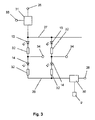
- Fig. 3 shows a schematic diagram of a key portion of two keyboard elements 2, 3 of the controllable keyboard illumination 15 according to the present invention after Fig. 2 ,
- the light sources 13 and 14 are formed as a multi-color double LED with respective resistors 32 connected in parallel between a distribution line 27 and a ground line, respectively, in series. Only the left strand (13-32-14-32) in the Fig. 3 considered, which applies to a keyboard element 2. The right-hand strand applies in the same way to the keyboard element 3.
- the distribution line 27 is connected via a switching element 31, for example a transistor, connected to a voltage terminal 26 switchable.
- the ground line 29 is connected via a control element 30, for example likewise a transistor, to a ground connection 28.
- the switching element 31 has a switching input 33 which is connected, for example, to an output, not shown, of the control device 20, either directly or via the adaptation device 21.
- the entire keyboard illumination 15 off or be turned on.
- the switching element 31 is turned on.
- the switching element 31 is switched off after a predetermined time, which is stored for example in the control device 20 in a memory, the light sources 13, 14 no longer light.
- the control element 30 is here connected to the brightness sensor 9, whereby a current influencing of the light sources 13, 14 is possible to change their brightness.
- the brightness sensor 9 can also be connected to the control device 20, which is then connected to the control element 30 with an output.
- the control element 30 may also have additional electronics.
- the controller 30 may be PWM controlled. Control element 30 and switching element 31 can also be reversed. Then the same applies above.
- the light sources 13, 14 in the form of light emitting diodes (LEDs) are connected in series and provided at their connection to a control terminal 34, which is connected to a corresponding output of the matching device 21 or the control device 20.
- the following states of the control terminal 34 are possible, but not limited thereto.
- An output of the matching device 21 and the associated control terminal 34 carries logic "zero" potential: it lights only the first light source 13 in their color and thus characterizes a first state of the corresponding drive function.
- the logical zero potential is preferably formed by the potential of the mass.
- An output of the adaptation device 21 and the associated control connection 34 carries logic "ONE" potential: only the second light source 14 illuminates in its color different from the first light source 13 and thus identifies a second state of the corresponding drive function.
- the logical ONE potential is preferably designed as operating potential and may have a voltage of, for example, 5 volts or 12 volts.
- An output of the matching device 21 and the associated control terminal 34 is "HIGH-AMOUNT": Both light sources 13 and 14 illuminate and produce a multicolor light which can be used to identify a third functional state.
- the control terminal 34 has a high resistance both with respect to the ground potential and to the operating potential, so that a current flow is complete, but preferably almost prevented.
- control terminal 34 has a constant or an alternating or a swelling or decaying signal, so that each light source 13, 14 is illuminated in a resulting color and / or in a resulting intensity.
- the printed circuit board used to accommodate the electronic and electromechanical components can be used for manual operations with or without keyboard illumination 15. Since the double LED are particularly space-saving in this example, this is advantageously possible.
- keyboard illumination 15 with different arrangements of the light sources 13, 14 are possible, some of which have already been described above.
- the individual control which is possible for light sources independent of color and double or single version, provides a manual operation with ease of use and advantageous function control with simultaneous illumination.
- the individual control of the light sources 13, 14 can also enable error states, for example as combination colors or the like.
- at least one light source 13, 14 has a special, predetermined color or that at least one light source has a flashing, changing and / or increasing or decreasing light intensity and / or color.
- the manual control 1 can be designed for both wired and wireless control of electromotive furniture drives.
Landscapes
- Circuit Arrangement For Electric Light Sources In General (AREA)
- Input From Keyboards Or The Like (AREA)
- Push-Button Switches (AREA)
Abstract
Description
Die Erfindung betrifft eine Handbedienung zur Bedienung eines elektromotorischen Möbelantriebs gemäß dem Oberbegriff des Anspruches 1.The invention relates to a manual control for operating an electromotive furniture drive according to the preamble of
Handbedienungen für elektromotorische Möbelantriebe sind in unterschiedlichen Ausführungen bekannt, wie zum Beispiel in Ausgestaltung als Handschalter für Betten und Fernsehsessel. Die Möbel weisen bestimmte Möbelteile auf, welche durch einen oder mehrere elektromotorische Antriebe verstellbar sind. Die Verstellung wird durch Betätigung der Bedienungseinheit aktiviert und deaktiviert.Manual controls for electric motor furniture drives are known in different versions, such as in design as a hand switch for beds and TV chairs. The furniture has certain furniture parts, which are adjustable by one or more electric motor drives. The adjustment is activated and deactivated by operating the operating unit.
Diese Handbedienungen können sowohl in drahtgebundener als auch drahtloser Verbindung mit einer Steuereinheit des zugeordneten elektromotorischen Möbelantriebs stehen. Als Handbedienungen mit drahtloser Übertragung sind zum Beispiel Funksender in verschiedenen Frequenzbereichen, Infrarotsender und auch Ultraschallsender in Gebrauch.These hand controls can be in wired as well as wireless connection with a control unit of the associated electromotive furniture drive. As hand controls with wireless transmission, for example, radio transmitters in different frequency ranges, infrared transmitter and ultrasonic transmitter in use.
Derartige Handbedienungen sind häufig mit einer Beleuchtung, zum Beispiel einer Tastaturbeleuchtung versehen, um es im Dunkeln einem Bediener zu ermöglichen, den gewünschten Bedienungsknopf leichter zu finden. Beispiele zur Illustration beschreiben die
Die elektromotorischen Möbelantriebe werden mit immer mehr Zusatzfunktionen, wie zum Beispiel im Pflegebereich das Sperren von Tastaturelementen für Patienten durch eine Pflegeperson, ausgerüstet. Dabei besteht der Bedarf nach einer differenzierteren Kennzeichnung der Tastaturelemente für den Benutzer.The electromotive furniture drives are equipped with more and more additional functions, such as in the care sector, the locking of keyboard elements for patients by a caregiver. There is a need for a more differentiated labeling of the keyboard elements for the user.
Es ist daher die Aufgabe der vorliegenden Erfindung, eine Handbedienung mit einer verbesserten Tastaturbeleuchtung für elektromotorische Möbelantriebe zu schaffen, welche die oben aufgeführten Nachteile behebt und zusätzliche Vorteile liefert.It is therefore the object of the present invention to provide a handset with improved keypad lighting for electromotive furniture drives, which overcomes the disadvantages listed above and provides additional benefits.
Die gestellte Aufgabe zur Bedienung eines elektromotorischen Antriebs für ein Möbel, mit zumindest zwei Tastaturelementen, welche mittels einer mit einer Spannungsquelle verbindbaren Tastaturbeleuchtung direkt oder indirekt beleuchtbar sind, ist dadurch gelöst, dass die Tastaturbeleuchtung zumindest eine erste Lichtquelle und zumindest eine zweite Lichtquelle aufweist, welche mittels einer Steuereinrichtung unabhängig voneinander ansteuerbar sind.The stated object of operating an electromotive drive for a piece of furniture, comprising at least two keyboard elements which can be illuminated directly or indirectly by means of a keyboard illumination that can be connected to a voltage source, is achieved in that the keyboard illumination has at least one first light source and at least one second light source can be controlled independently by means of a control device.
Dadurch wird eine vorteilhaft globale und/oder selektive Beleuchtung der Tastaturelemente und somit eine Kennzeichnung der Tastaturelemente, indem sie einzeln und unabhängig voneinander ansteuerbar sind, ermöglicht.As a result, an advantageous global and / or selective illumination of the keyboard elements and thus an identification of the keyboard elements, by being individually and independently controllable, allows.
Vorteilhafte Weiterbildungen der Erfindung sind den Unteransprüchen zu entnehmen.Advantageous developments of the invention can be found in the dependent claims.
Die Steuereinrichtung kann in der Handbedienung angeordnet sein. Andere Orte, wie zum Beispiel in der Steuerung des elektromotorischen Möbelantriebs sind möglich. Die Steuereinrichtung ist zur individuellen Ansteuerung einer jeden einzelnen Lichtquelle mit dieser jeweils verbunden. Die Steuereinrichtung erhält von der Steuerung des elektromotorischen Möbelantriebs oder von anderer Seite, zum Beispiel über eine manuelle Eingabe, Informationen über eingestellte Zustände, beispielsweise "freigegeben" oder "gesperrt", der einzelnen Antriebsfunktionen. Demgemäß steuert die Steuereinrichtung die Lichtquellen separat an, wodurch die zu den Lichtquellen korrespondierenden Tastaturelemente entsprechend gekennzeichnet werden, zum Beispiel durch "Licht Aus = Funktion gesperrt" oder "Licht Ein = Funktion freigegeben". Es ist auch möglich, dass zur Kennzeichnung unterschiedliche Helligkeitsstufen verwendet werden.The control device can be arranged in the manual operation. Other places, such as in the control of the electromotive furniture drive are possible. The control device is connected to the individual control of each individual light source with this in each case. The control device receives from the control of the electromotive furniture drive or from another side, for example via a manual input, information about set states, such as "enabled" or "disabled", the individual drive functions. Accordingly, the control device controls the light sources separately, whereby the keyboard elements corresponding to the light sources are marked accordingly, for example by "light off = function disabled" or "light on = function enabled". It is also possible that different brightness levels are used for the identification.
Hierzu ist eine Ausführung derart ausgestaltet, dass dem ersten Tastaturelement der zumindest zwei Tastaturelemente die erste Lichtquelle und dem zweiten Tastaturelement der zumindest zwei Tastaturelemente die zweite Lichtquelle zugeordnet ist, das heißt, die Lichtquellen befinden sich in unmittelbarer Nähe des jeweiligen Tastaturelementes oder sind in diesem integriert.For this purpose, an embodiment is configured such that the first light source is associated with the first keyboard element of the at least two keyboard elements, and the second light source is associated with the second keyboard element of the at least two keyboard elements means that the light sources are in the immediate vicinity of the respective keyboard element or are integrated in this.
In einer alternativen Ausgestaltung ist vorgesehen, dass die zumindest eine erste Lichtquelle jeweils über einen Lichtleiter zur Beleuchtung der zumindest zwei Tastaturelemente mit einem jeweiligen Tastaturelement verbunden ist, und dass jedem der zumindest zwei Tastaturelemente eine zweite Lichtquelle zugeordnet ist.In an alternative embodiment it is provided that the at least one first light source is connected in each case via a light guide for illuminating the at least two keyboard elements with a respective keyboard element, and that each of the at least two keyboard elements is associated with a second light source.
In dieser Ausführung kann die erste Lichtquelle an einer von den Tastaturelementen entfernten Position in der Handbedienung angeordnet sein, wobei ihr Licht über Lichtleiter zu allen, bzw. den zu beleuchtenden Tastaturelementen geführt wird. Hierbei kann dieses Licht zum Beispiel eine erste Farbe aufweisen. Weiterhin ist jedem Tastaturelement eine zweite Lichtquelle zugeordnet. Alle Lichtquellen sind individuell ansteuerbar und zum Beispiel als Leuchtdioden (LED) ausgebildet. Die zweiten Lichtquellen werden nun je nach Funktionszustand ein- oder ausgeschaltet, wobei eine eingeschaltete zweite Lichtquelle ihr Licht dem von der ersten Lichtquelle über Lichtleiter zugeführtem Licht überlagert. Dadurch kann die Gesamtlichthelligkeit dieses Tastaturelementes verändert werden, zum Beispiel heller oder dunkler. Sind die Lichtquellen verschiedenfarbig, so sind Mischfarben bei eingeschalteter zweiter Lichtquelle zur Funktionskennzeichnung einfach möglich.In this embodiment, the first light source may be located at a position remote from the keyboard elements in the manual operation, with their light being guided via optical fibers to all, or the keyboard elements to be illuminated. In this case, for example, this light may have a first color. Furthermore, each keyboard element is associated with a second light source. All light sources can be individually controlled and designed, for example, as light-emitting diodes (LED). The second light sources are now switched on or off depending on the functional state, wherein an activated second light source their light superimposed on the light supplied from the first light source via light. As a result, the overall light brightness of this keyboard element can be changed, for example, lighter or darker. If the light sources are of different colors, mixed colors are easily possible when the second light source is switched on for function identification.
In einer weiteren alternativen Ausführung sind jedem der zumindest zwei Tastaturelemente die zumindest eine erste Lichtquelle und die zumindest eine zweite Lichtquelle zugeordnet.In a further alternative embodiment, each of the at least two keyboard elements is assigned the at least one first light source and the at least one second light source.
Auch hierbei kann es vorgesehen sein, dass die erste Lichtquelle eine erste Farbe aufweist und die zweite Lichtquelle eine dazu unterschiedliche Farbe aufweist. So kann zum Beispiel ein Tastaturelement ohne Funktion mit einer eingeschalteten ersten roten Lichtquelle gekennzeichnet werden. Ist die Funktion vorhanden, wird nur die zweite Lichtquelle mit der unterschiedlichen Farbe, zum Beispiel grün, eingeschaltet. So kann eine Kennzeichnung der Tastaturelemente mittels einer selektiven farbigen Beleuchtung vorteilhaft erfolgen. Die farbigen LED können auch als Mehrfarben-LED ausgebildet sein.Here, too, provision may be made for the first light source to have a first color and the second light source to have a different color for this purpose. For example, a keyboard element may be marked without function with a first red light source turned on. If the function is present, only the second light source with the different color, for example green, will be switched on. Thus, an identification of the keyboard elements by means of a selective color illumination can be done advantageously. The colored LED can also be designed as a multi-color LED.
Hierbei ist es besonders vorteilhaft, dass die zumindest eine erste Lichtquelle und/oder die zumindest eine zweite Lichtquelle jeweils eine Mehrfarben-LED ist. Dadurch wird der begrenzte Einbauraum in einer Handbedienung nur gering beansprucht. Derartige Mehrfarben-LED können zum Beispiel durch mindestens zwei verschiedenfarbige Lichtquellen gebildet sein.In this case, it is particularly advantageous that the at least one first light source and / or the at least one second light source is in each case a multicolor LED. As a result, the limited installation space in a manual control is only slightly stressed. Such multi-color LEDs can be formed, for example, by at least two differently colored light sources.
In einer anderen Ausführungsform können mehrere ein- und/oder mehrfarbige LED's dicht aneinander gesetzt sein, so dass diese zusammengesetzte Baugruppe als einzelnes Bauteil erscheint.In another embodiment, a plurality of single and / or multi-colored LEDs can be placed close to each other, so that this composite assembly appears as a single component.
In bevorzugter Ausführung weist die Steuereinrichtung zumindest einen Mikrokontroller auf. Dessen Ausgänge können mit den jeweiligen Lichtquellen verbunden sein. Bei umfangreichen Handbedienungen mit mehr als zwei Tastaturelementen kann die Anzahl von Ausgängen eines Mikrokontrollers nicht ausreichen, wobei dann mehrere Mikrokontroller in Kaskadenschaltung vorgesehen sein können.In a preferred embodiment, the control device has at least one microcontroller. Its outputs can be connected to the respective light sources. With extensive manual operations with more than two keyboard elements, the number of outputs of a microcontroller may not be sufficient, in which case several microcontrollers may be provided in cascade connection.
Eine alternative Ausführung, die sich insbesondere bei mehr als zwei Tastaturelementen vorteilhaft eignet, sieht vor, dass die Steuereinrichtung über eine Anpassungseinrichtung mit der zumindest einen ersten Lichtquelle und der zumindest einen zweiten Lichtquelle verbunden ist. In diesem Fall kann die Steuereinrichtung ein serielles Ausgangssignal liefern, welches in bevorzugter Ausgestaltung der Anpassungseinrichtung als Seriell-Parallel-Umsetzer in dieser in ein paralleles Signal zur Ansteuerung der Lichtquellen umgesetzt wird. Dabei ist vorteilhaft, dass die Verbindungen von der Steuereinrichtung zu der Anpassungseinrichtung in nur geringer Anzahl, zum Beispiel vier Leitungen, notwendig sind. Dadurch wird Bauraum gespart, zum Beispiel auf einer gedruckten Schaltung, der im engen Handschalter begrenzt ist. Auf Grund der geringen Anzahl von Leitungen ist es auch möglich, dass die Steuereinrichtung außerhalb der Handbedienung, zum Beispiel in der Steuerung des elektromotorischen Möbelantriebs, angeordnet sein kann, wobei ein Verbindungskabel zur Handbedienung weniger Leitungen beansprucht.An alternative embodiment, which is particularly advantageous for more than two keyboard elements, provides that the control device is connected via an adapter to the at least one first light source and the at least one second light source. In this case, the control device can provide a serial output signal, which is implemented in a preferred embodiment of the matching device as a serial-parallel converter in this in a parallel signal for driving the light sources. It is advantageous that the connections from the control device to the adapter device in only a small number, for example, four lines, are necessary. As a result, space is saved, for example on a printed circuit, which is limited in the narrow hand switch. Due to the small number of lines, it is also possible that the control device outside the manual control, for example, in the control of the electromotive furniture drive, can be arranged, wherein a connecting cable for manual operation requires less lines.
Es ist weiterhin bevorzugt, dass der zumindest eine Seriell-Parallel-Umsetzer ein Schieberegister ist. Auch im Fall von umfangreichen Tastaturelementen können mehrere Schieberegister, die als Standardbauteile kostengünstig verfügbar sind, kaskadiert verschaltet werden.It is further preferred that the at least one serial-to-parallel converter is a shift register. Even in the case of extensive keyboard elements, several Shift registers, which are available as standard components at low cost, are cascaded.
Durch die individuelle Ansteuerung von verschiedenfarbigen Lichtquellen können auch Mischfarben erzeugt werden, wenn sich das erzeugte Licht überlagert. Somit können drei Farbzustände mit zwei Lichtquellen ermöglicht werden. Dazu kann zum Beispiel der jeweilige Ausgang der Steuereinrichtung bzw. der Anpassungseinrichtung auf logisch "EINS", "NULL" und "HOCHOHMIG" eingestellt werden. Im Falle der Schieberegister sind auf Grund des Aufbaus angeschlossene Gruppen dementsprechend ansteuerbar, wohingegen bei einer parallelen Ankopplung an jeweils einen individuell steuerbaren Einzelausgang, zum Beispiel eines Mikrokontrollers, dementsprechende Ansteuerungen einzelner Lichtquellen möglich sind.The individual control of different colored light sources and mixed colors can be generated when the generated light is superimposed. Thus, three color states with two light sources can be made possible. For this purpose, for example, the respective output of the control device or the adjustment device can be set to logic "ONE", "ZERO" and "HOCHOHMIG". In the case of the shift registers connected groups due to the structure are accordingly controlled, whereas in a parallel coupling to an individually controllable individual output, for example, a microcontroller, corresponding controls individual light sources are possible.
In weiterer Ausgestaltung ist es vorgesehen, dass die Helligkeit der zumindest einen ersten Lichtquelle und/oder der zumindest einen zweiten Lichtquelle einstellbar ist. Dies kann in einer weiteren Ausführung auch mittels eines Helligkeitssensors erfolgen, wobei eine Anpassung an die Umgebungshelligkeit möglich ist. Der Helligkeitssensor ist bevorzugt an der Handbedienung angeordnet.In a further embodiment, it is provided that the brightness of the at least one first light source and / or the at least one second light source is adjustable. This can be done in a further embodiment by means of a brightness sensor, with an adaptation to the ambient brightness is possible. The brightness sensor is preferably arranged on the hand control.
Gemäß einer weiteren Ausführungsform ist eine Anordnung mit Lichtquellen vorgesehen, wobei sich die Lichtintensitäten zumindest einer erste Lichtquelle gegenüber zumindest einer zweiten Lichtquelle voneinander unterscheiden. Der Unterschied der Intensitäten kann durch identische und/oder unterschiedliche Versorgungsspannung und/oder einer getakteten bzw. gepulsten Versorgungsspannung der Lichtquellen gebildet sein.According to a further embodiment, an arrangement with light sources is provided, the light intensities of at least one first light source being different from at least one second light source. The difference of the intensities can be formed by identical and / or different supply voltage and / or a pulsed or pulsed supply voltage of the light sources.
Die Handbedienung kann einen mit der Steuereinrichtung verbundenen Bedienungssensor zum automatischen Einschalten der zumindest einen ersten Lichtquelle und zumindest einen zweiten Lichtquelle beim Berühren und/oder Ergreifen der Handbedienung aufweisen. Auch eine Dauerbeleuchtung, zum Beispiel zumindest durch eine erste Lichtquelle, ist möglich, deren Helligkeit sich zum Beispiel beim Berühren erhöht und nach Bedienung wieder abschwächt.The hand control may have an operating sensor connected to the control device for automatically switching on the at least one first light source and at least one second light source for touching and / or grasping the hand control. Even a continuous lighting, for example, at least by a first light source, is possible, the brightness increases, for example, when touched and weakened again after operation.
Alternativ ist vorgesehen, dass die Steuereinrichtung für eine vorher festlegbare verzögerte Ausschaltung der zumindest einen ersten Lichtquelle und zumindest einen zweiten Lichtquelle nach deren Einschalten ausgebildet ist.Alternatively, it is provided that the control device is designed for a previously definable delayed switch-off of the at least one first light source and at least one second light source after it has been switched on.
In einer weiteren Ausführung ist die Handbedienung mit einer am Rand der Handbedienung zumindest abschnittsweise umlaufend ausgebildeten Rahmenbeleuchtung versehen. Auch eine Leuchte mit einer Taschenlampenfunktion kann vorgesehen sein.In a further embodiment, the manual control is provided with a frame illumination formed at least partially peripherally on the edge of the hand control. Also, a lamp with a flashlight function can be provided.
Diese Zusatzfunktionen der Rahmenbeleuchtung und/oder Taschenlampenfunktion können ebenfalls mittels der Steuereinrichtung ansteuerbar sein.These additional functions of the frame lighting and / or flashlight function can also be controlled by means of the control device.
Die Steuereinrichtung kann auch weitere Anzeigen ansteuern, mit denen sie verbunden sein kann. So ist es zum Beispiel möglich, dass im Falle einer drahtlosen Handbedienung eine Anzeige bei Sende-/Empfangsbetrieb erfolgt. Hierbei kann die Steuereinrichtung auch Bestandteil eines Mikrokontrollers sein, der für die Sende-/Empfangsfunktionen der Handbedienung ausgelegt ist.The control device can also control other displays with which it can be connected. It is thus possible, for example, that in the case of a wireless manual operation, an indication is given during transmission / reception operation. In this case, the control device may also be part of a microcontroller which is designed for the transmit / receive functions of the manual control.
Es ist auch möglich, dass die Anpassungseinrichtung oder die Steuereinrichtung mit einer Zustandsanzeige aller Funktionen ausgerüstet ist, zum Beispiel in Gestalt einer Siebensegmentanzeige oder dergleichen.It is also possible that the adaptation device or the control device is equipped with a status display of all functions, for example in the form of a seven-segment display or the like.
Es kann auch möglich sein, dass beim Betätigen eines Tastaturelementes sich dessen Beleuchtung durch die Lichtquellen verändert und/oder andere Lichtquellen der Tastaturbeleuchtung in ihrer Leuchtfunktion veränderbar sind.It may also be possible that upon actuation of a keyboard element, its illumination is changed by the light sources and / or other light sources of the keyboard illumination can be changed in their lighting function.
Die Erfindung wird nun anhand von Ausführungsbeispielen mit Bezug auf die beigefügten Figuren näher erläutert. Hierbei zeigt:
- Fig. 1
- eine schematische Draufsicht auf eine beispielhafte Ausführung einer erfindungsgemäßen Handbedienung;
- Fig. 2
- ein schematisches Blockschaltbild einer beispielhaften Ausführung einer ansteuerbaren Tastaturbeleuchtung gemäß der vorliegenden Er-findung; und
- Fig. 3
- ein schematisches Schaltbild eines Tastenabschnitts einer ansteuerba-ren Tastaturbeleuchtung gemäß der vorliegenden Erfindung.
- Fig. 1
- a schematic plan view of an exemplary embodiment of a hand control according to the invention;
- Fig. 2
- a schematic block diagram of an exemplary embodiment of a controllable keyboard illumination according to the present invention; and
- Fig. 3
- a schematic circuit diagram of a key portion of a control keyboard keypad illumination according to the present invention.
Gleiche oder ähnliche Funktionseinheiten sind in den Figuren mit gleichen Bezugszeichen versehen.The same or similar functional units are provided in the figures with the same reference numerals.
Die Handbedienung 1 weist ein Gehäuse 4 auf, in welchem zum Beispiel eine nicht gezeigte Platine mit einer gedruckten Schaltung zur Aufnahme elektronischer und elektromechanischer Bauteile angeordnet ist. Weiterhin ist die Handbedienung 1 in dem hier gezeigten Beispiel mit acht Tastaturelementen 2 und 3 versehen, von denen jeweils zwei übereinander liegende für eine Möbelantriebsfunktion vorgesehen sind. Es sind hier der Übersicht wegen nur die linken Tastaturelemente 2 und 3 bezeichnet, für die rechts daneben liegenden gelten die weiteren Beschreibungen analog. Die Tastaturelemente 2, 3 sind mit einer Tastaturbeleuchtung gekoppelt, die weiter unten noch ausführlich erläutert wird.The
In diesem Beispiel weist die Handbedienung 1 weiterhin Folgendes auf: eine zumindest abschnittsweise oder eine umlaufende Rahmenbeleuchtung 5; eine Leuchte 6 an der Frontseite mit Taschenlampenfunktion; ein erstes Anzeigeelement 7 für eine beliebige Funktion, zum Beispiel aktiver Zustand der Steuerung; wenigstens ein zweites Anzeigeelement 8 zur Anzeige eines Verstellvorgangs bei betätigtem Tastaturelement 2, 3; ein Helligkeitssensor 9 zur Steuerung der Helligkeit der Tastaturbeleuchtung 15; ein drittes Anzeigeelement 10 in Form einer Siebensegmentanzeige, die unten noch erläutert wird; einen Bedienungssensor 11, welcher abtastet, ob die Handbedienung zur Betätigung berührt oder ergriffen wird; und einen Anschluss 12 für ein nicht gezeigtes Verbindungskabel zu einer Steuerung eines elektromotorischen Möbelantriebs, der durch diese Handbedienung bedienbar ist.In this example, the
In einer anderen nicht näher dargestellen Ausführungsform einer Handbedienung 1 ist diese mit drahtlos arbeitenden Übertragungsmitteln ausgestattet, so dass die einzelnen Steuer- und Meldebefehle beispielsweise mittels einer Funkstrecke und/oder mittels einer Infrarotlichtstrecke übertragen werden, wobei der Anschluß 12 entfällt.In another unspecified dargestellen embodiment of a
Die Handbedienung 1 ist mit einer Tastaturbeleuchtung 15 ausgestattet. Die Tastaturbeleuchtung 15 der vorliegenden Erfindung ist mit zumindest einer ersten Lichtquelle und zumindest einer zweiten Lichtquelle versehen, welche separat und individuell ansteuerbar sind. Dabei sind mechanische Aufbauten in unterschiedlichen Ausführungen möglich, von denen
Die Anpassungseinrichtung 21 ist hier mit Seriell-Parallel-Umsetzern 22 in Ausführung mit zwei kaskadierten Schieberegistern gebildet. Die Ausgänge des in der Zeichnung oberen Schieberegisters sind mit den Anschlüssen der Verbindungen 16, 17 verbunden. Das untere Schieberegister ist über eine Kopplung mit dem oberen Schiebregister in Kaskade verbunden, und weist einen Kopplungsanschluss 25 für weitere Kaskadierungen von Schieberegistern auf. Das untere Schieberegister ist mit seinen Ausgängen mit dem Rahmenleuchtelement 5, der Leuchte 6 und den Anzeigeelementen 5 bis 8 über Einzelverbindungen und mit dem dritten Anzeigeelement 10 über vier Leitungen verbunden.The
Die Eingänge der Schieberegister sind jeweils über vier Leitungen mit der Steuereinrichtung 20 verbunden. Diese vier Leitungen dienen hier zum Beispiel zur Übertragung von Funktionen zur Steuerung der Schieberegister (Enable, Latch, Clock) und eines seriellen Signals von der Steuereinrichtung 20 zur Anpassungseinrichtung 21. Die Steuereinrichtung 20 weist einen Eingangsanschluss 24 auf, der nur schematisch zu verstehen ist.The inputs of the shift registers are each connected to the
Über den Eingangsanschluss 24 erhält die Steuereinrichtung 20 Informationen, zum Beispiel von einer Steuerung des am Anschluss 12 der Handbedienung 1 (
Damit ist eine individuelle Ansteuerung der Lichtquellen 13, 14 der Tastaturbeleuchtung 15 ermöglicht.For an individual control of the
Die an dem unteren Schieberegister angeschlossenen Komponenten 5 bis 8 werden je nach Eingabesignal an der Steuereinrichtung 20 ein- oder ausgeschaltet. Das Eingabesignal hierfür kann zum Beispiel auch manuell eingegeben werden. Auch ist es möglich, dass derartige Einzelkomponenten direkt mit einem Ausgang der Steuereinrichtung verbunden sind.The
Das dritte Anzeigeelement 10 ist nur schematisch mit vier Leitungen gezeigt und zeigt den eingestellten Zustand des parallelen Signals für eine Gruppe 2 oder 3 an. Für beide Gruppen ist das dritte Anzeigeelement dann, was leicht vorstellbar ist, mit acht Leitungen angeschlossen, wobei ein weiteres Schieberegister dazu erforderlich ist.The
Die Lichtquellen 13 und 14 sind als Mehrfarben-Doppel-LED mit jeweiligen Widerständen 32 ausgebildet, die parallel zwischen einer Verteilerleitung 27 und einer Masseleitung jeweils in Reihe angeschlossen sind. Es wird nur der linke Strang (13-32-14-32) in der
Die Verteilerleitung 27 ist über ein Schaltelement 31, zum Beispiel einen Transistor, mit einem Spannungsanschluss 26 schaltbar verbunden. Die Masseleitung 29 ist über ein Steuerelement 30, zum Beispiel ebenfalls ein Transistor, mit einem Masseanschluss 28 verbunden. Das Schaltelement 31 besitzt einen Schalteingang 33, der zum Beispiel mit einem nicht gezeigten Ausgang der Steuereinrichtung 20 entweder direkt oder über die Anpassungseinrichtung 21 verbunden ist. Hierdurch kann die gesamte Tastaturbeleuchtung 15 aus- bzw. eingeschaltet werden. Zum Beispiel wird durch Aktivierung des Bedienungssensors 11 (
Das Steuerelement 30 ist hier mit dem Helligkeitssensor 9 verbunden, wodurch eine Strombeeinflussung der Lichtquellen 13, 14 zur Veränderung ihrer Helligkeit möglich ist. Der Helligkeitssensor 9 kann aber auch mit der Steuereinrichtung 20 verbunden sein, welche dann mit einem Ausgang an das Steuerelement 30 angeschlossen ist. Das Steuerelement 30 kann auch eine zusätzliche Elektronik aufweisen. Zum Beispiel kann das Steuerelement 30 PWM-gesteuert ausgebildet sein. Steuerelement 30 und Schaltelement 31 können auch vertauscht sein. Dann gilt oben gesagtes analog.The
Die Lichtquellen 13, 14 in Ausführung als Leuchtdioden (LED) sind in Reihe geschaltet und an ihrer Verbindung mit einem Steueranschluss 34 versehen, welcher mit einem korrespondierenden Ausgang der Anpassungseinrichtung 21 oder der Steuereinrichtung 20 verbunden ist. Folgende Zustände des Steueranschlusses 34 sind möglich, aber nicht darauf begrenzt.The
Ein Ausgang der Anpassungseinrichtung 21 und der damit verbundene Steueranschluss 34 führt logisches "NULL"-Potential: es leuchtet nur die erste Lichtquelle 13 in ihrer Farbe und kennzeichnet somit einen ersten Zustand der korrespondierenden Antriebsfunktion. Das logische NULL-Potential ist vorzugweise durch das Potential der Masse gebildet.
Ein Ausgang der Anpassungseinrichtung 21 und der damit verbundene Steueranschluss 34 führt logisches "EINS"-Potential: es leuchtet nur die zweite Lichtquelle 14 in ihrer zur ersten Lichtquelle 13 unterschiedlichen Farbe und kennzeichnet somit einen zweiten Zustand der korrespondierenden Antriebsfunktion. Das logische EINS-Potential ist vorzugsweise als Betriebspotential ausgebildet und kann eine Spannung von beispielsweise 5 Volt oder 12 Volt aufweisen.An output of the
An output of the
Ein Ausgang der Anpassungseinrichtung 21 und der damit verbundene Steueranschluss 34 ist "HOCHOHMIG": Beide Lichtquellen 13 und 14 leuchten und erzeugen ein mehrfarbiges Licht, welches zur Kennzeichnung eines dritten Funktionszustands verwendbar ist. Dabei weist der Steueranschluss 34 sowohl gegenüber dem Massepotential als auch gegenüber dem Betriebspotential einen hohen Widerstand auf, so dass ein Stromfluß vollständig, jedoch vorzugsweise nahezu unterbunden ist.An output of the
Gemäß einer weiteren Ausführungsform weist der Steueranschluss 34 ein konstantes oder ein wechselndes oder ein an- bzw. abschwellendes Signal auf, so dass jede Lichtquelle 13, 14 in einer daraus resultierenden Farbe und/oder in einer daraus resultierenden Intensität leuchtet.According to a further embodiment, the
Die verwendete Leiterplatte zur Aufnahme der elektronischen und elektromechanischen Bauteile kann für Handbedienungen mit oder ohne Tastaturbeleuchtung 15 verwendet werden. Da die Doppel-LED in diesem Beispiel besonders raumsparend sind, ist dies vorteilhaft möglich.The printed circuit board used to accommodate the electronic and electromechanical components can be used for manual operations with or without
Weitere Ausführungen der Tastaturbeleuchtung 15 mit unterschiedlichen Anordnungen der Lichtquellen 13, 14 sind möglich, von denen einige oben bereits beschrieben sind. Durch die individuelle Ansteuerung, die für Lichtquellen unabhängig von Farbe und Doppel- bzw. Einzelausführung möglich ist, ist eine Handbedienung mit Bedienungskomfort und vorteilhafter Funktionskontrolle mit gleichzeitiger Beleuchtung geschaffen.Further embodiments of the
Die Erfindung ist nicht auf das erläuterte Ausführungsbeispiel beschränkt, sondern im Rahmen der beigefügten Ansprüche modifizierbar.The invention is not limited to the illustrated embodiment, but can be modified within the scope of the appended claims.
Es ist denkbar, dass die individuelle Ansteuerung der Lichtquellen 13, 14 auch Fehlerzustände, zum Beispiel als Kombinationsfarben oder ähnlich, ermöglichen kann. Somit ist es denkbar, dass mindestens eine Lichtquelle 13, 14 eine spezielle, vorbestimmte Farbe aufweist oder dass wenigstens eine Lichtquelle eine blinkende, wechselnde und/oder an- bzw. abschwellende Leuchtintensität und/oder Farbe aufweist.It is conceivable that the individual control of the
Die Handbedienung 1 kann sowohl für drahtgebundene als auch drahtlose Steuerung elektromotorischer Möbelantriebe ausgeführt sein.The
- 11
- Handbedienungmanual operation
- 22
- Erstes TastaturelementFirst keyboard element
- 33
- Zweites TastaturelementSecond keyboard element
- 44
- Gehäusecasing
- 55
- Rahmenbeleuchtungframe lighting
- 66
- Leuchtelamp
- 77
- Erstes AnzeigeelementFirst display element
- 88th
- Zweites AnzeigeelementSecond display element
- 99
- Helligkeitssensorbrightness sensor
- 1010
- Drittes AnzeigeelementThird display element
- 1111
- Bedienungssensoroperation sensor
- 1212
- Anschlussconnection
- 1313
- Erste LichtquelleFirst light source
- 1414
- Zweite LichtquelleSecond light source
- 1515
- Tastaturbeleuchtungkeyboard light
- 1616
- Erste VerbindungFirst connection
- 1717
- Zweite VerbindungSecond connection
- 1818
- Steuerverbindungcontrol connection
- 1919
- EinzelverbindungItemized
- 2020
- Steuereinrichtungcontrol device
- 2121
- Anpassungseinrichtungmatcher
- 2222
- Seriell-Parallel-UmsetzerSerial-to-parallel converter
- 2323
- Kopplungcoupling
- 2424
- Eingangsanschlussinput port
- 2525
- Kopplungsanschlusscoupling connector
- 2626
- Spannungsanschlussvoltage connection
- 2727
- Verteilerleitungdistribution line
- 2828
- Masseanschlussground connection
- 2929
- Masseleitungground line
- 3030
- Steuerelementcontrol
- 3131
- Schaltelementswitching element
- 3232
- Widerstandresistance
- 3333
- Schalteingangswitching input
- 3434
- Steueranschlusscontrol connection
Claims (15)
Applications Claiming Priority (1)
| Application Number | Priority Date | Filing Date | Title |
|---|---|---|---|
| DE202008006070U DE202008006070U1 (en) | 2008-05-02 | 2008-05-02 | Manual control for operating an electromotive furniture drive |
Publications (3)
| Publication Number | Publication Date |
|---|---|
| EP2113931A2 true EP2113931A2 (en) | 2009-11-04 |
| EP2113931A3 EP2113931A3 (en) | 2013-09-04 |
| EP2113931B1 EP2113931B1 (en) | 2019-06-12 |
Family
ID=40934190
Family Applications (1)
| Application Number | Title | Priority Date | Filing Date |
|---|---|---|---|
| EP09157433.5A Active EP2113931B1 (en) | 2008-05-02 | 2009-04-06 | Manual control for operating an electrically motor driven furniture drive |
Country Status (4)
| Country | Link |
|---|---|
| EP (1) | EP2113931B1 (en) |
| DE (1) | DE202008006070U1 (en) |
| DK (1) | DK2113931T3 (en) |
| ES (1) | ES2736000T3 (en) |
Families Citing this family (4)
| Publication number | Priority date | Publication date | Assignee | Title |
|---|---|---|---|---|
| CH702054B1 (en) * | 2009-10-26 | 2014-05-15 | Naderer Brandsimulation Ag | Remote control and display device. |
| DE102011082258A1 (en) * | 2011-09-07 | 2013-03-07 | Siemens Aktiengesellschaft | Protective switching device with a status indicator |
| US20150241857A1 (en) * | 2012-02-28 | 2015-08-27 | Dewertokin Gmbh | Operating unit of a control device of an adjusting drive for furniture |
| DE102015203510B3 (en) * | 2015-02-27 | 2016-07-21 | Phoenix Contact Gmbh & Co. Kg | Overvoltage protection device with a space-optimized status display |
Citations (2)
| Publication number | Priority date | Publication date | Assignee | Title |
|---|---|---|---|---|
| DE9318083U1 (en) | 1993-11-26 | 1994-02-03 | Dewert Antriebs- und Systemtechnik GmbH & Co KG, 32278 Kirchlengern | Hand switch |
| DE19501976C2 (en) | 1994-01-29 | 1998-07-16 | Dietmar Koch | Hand switch |
Family Cites Families (5)
| Publication number | Priority date | Publication date | Assignee | Title |
|---|---|---|---|---|
| US5486986A (en) * | 1994-03-29 | 1996-01-23 | Brada; Carla R. | Remote control illuminated magnifier |
| DE10118015A1 (en) * | 2001-04-10 | 2002-10-24 | Cimosys Ag Goldingen | Electric motor furniture drive for adjusting parts of furniture relative to each other, has manual switch for selecting drive units in predefined sequence, and further function control surfaces |
| DE10209622B4 (en) * | 2002-03-05 | 2006-02-02 | Preh Gmbh | Optical display |
| US7027037B2 (en) * | 2003-04-08 | 2006-04-11 | Intermec Ip Corp. | Conditionally illuminated keypad legends |
| US7319426B2 (en) * | 2005-06-16 | 2008-01-15 | Universal Electronics | Controlling device with illuminated user interface |
-
2008
- 2008-05-02 DE DE202008006070U patent/DE202008006070U1/en not_active Expired - Lifetime
-
2009
- 2009-04-06 EP EP09157433.5A patent/EP2113931B1/en active Active
- 2009-04-06 ES ES09157433T patent/ES2736000T3/en active Active
- 2009-04-06 DK DK09157433.5T patent/DK2113931T3/en active
Patent Citations (2)
| Publication number | Priority date | Publication date | Assignee | Title |
|---|---|---|---|---|
| DE9318083U1 (en) | 1993-11-26 | 1994-02-03 | Dewert Antriebs- und Systemtechnik GmbH & Co KG, 32278 Kirchlengern | Hand switch |
| DE19501976C2 (en) | 1994-01-29 | 1998-07-16 | Dietmar Koch | Hand switch |
Also Published As
| Publication number | Publication date |
|---|---|
| ES2736000T3 (en) | 2019-12-23 |
| EP2113931B1 (en) | 2019-06-12 |
| DK2113931T3 (en) | 2019-09-16 |
| DE202008006070U1 (en) | 2009-09-10 |
| EP2113931A3 (en) | 2013-09-04 |
Similar Documents
| Publication | Publication Date | Title |
|---|---|---|
| EP2113931B1 (en) | Manual control for operating an electrically motor driven furniture drive | |
| DE60303637T2 (en) | Switch with illuminated button | |
| DE19945775A1 (en) | Lamp arrangement for vehicle with several illumination surfaces for perceiving determined signaling functions and with control circuit for controlling individual illumination surfaces | |
| EP2437574B1 (en) | Control device for controlling a multicolour light source and lighting device | |
| DE102005059735A1 (en) | Pointer indicating device for control panel of vehicle air conditioning system has operating unit which is of cylindrical form whereby clock shield, display area and pointer are arranged inside operating unit | |
| DE102007024150B4 (en) | Multifunction control device and method for controlling a multifunction control device | |
| EP1871145B1 (en) | Illumination system | |
| DE102010043013B4 (en) | Lighting device and method for lighting | |
| DE69326746T2 (en) | Functional display device with multi-colored buttons | |
| EP2334218B1 (en) | Kitchen appliance with motor speed display | |
| DE4010998A1 (en) | Electronic control for household appliance - uses digital display to set time, temp. etc. for oven, washer, dryer, etc. | |
| EP1418384B1 (en) | Display device with lighting assembly for an electrical household appliance | |
| WO2006072340A1 (en) | Actuator unit for a vehicle component | |
| EP1811535A1 (en) | Electrical switch and/or actuator element with optical indicator | |
| EP1956754A1 (en) | Control device for building systems technology | |
| DE10227803B4 (en) | Operating element for motor vehicle components | |
| EP2287996B1 (en) | Switching device for a motor vehicle | |
| EP3796356B1 (en) | Foot switch for medical devices | |
| DE10062687A1 (en) | Steller in particular of a motor vehicle with a position-changeable brand | |
| EP1098112B1 (en) | Gear selection device | |
| DE202013104307U1 (en) | LEDs on PCB strips | |
| DE10006164B4 (en) | display device | |
| DE29617827U1 (en) | Control device for solariums | |
| DE102004029931B4 (en) | Connection circuit for luminaire modules | |
| WO2024083728A1 (en) | Illuminating device |
Legal Events
| Date | Code | Title | Description |
|---|---|---|---|
| PUAI | Public reference made under article 153(3) epc to a published international application that has entered the european phase |
Free format text: ORIGINAL CODE: 0009012 |
|
| AK | Designated contracting states |
Kind code of ref document: A2 Designated state(s): AT BE BG CH CY CZ DE DK EE ES FI FR GB GR HR HU IE IS IT LI LT LU LV MC MK MT NL NO PL PT RO SE SI SK TR |
|
| PUAL | Search report despatched |
Free format text: ORIGINAL CODE: 0009013 |
|
| AK | Designated contracting states |
Kind code of ref document: A3 Designated state(s): AT BE BG CH CY CZ DE DK EE ES FI FR GB GR HR HU IE IS IT LI LT LU LV MC MK MT NL NO PL PT RO SE SI SK TR |
|
| RIC1 | Information provided on ipc code assigned before grant |
Ipc: H01H 9/02 20060101AFI20130729BHEP Ipc: A47C 31/00 20060101ALI20130729BHEP |
|
| RAP1 | Party data changed (applicant data changed or rights of an application transferred) |
Owner name: DEWERTOKIN GMBH |
|
| 17P | Request for examination filed |
Effective date: 20140304 |
|
| RBV | Designated contracting states (corrected) |
Designated state(s): AT BE BG CH CY CZ DE DK EE ES FI FR GB GR HR HU IE IS IT LI LT LU LV MC MK MT NL NO PL PT RO SE SI SK TR |
|
| STAA | Information on the status of an ep patent application or granted ep patent |
Free format text: STATUS: EXAMINATION IS IN PROGRESS |
|
| 17Q | First examination report despatched |
Effective date: 20170202 |
|
| GRAP | Despatch of communication of intention to grant a patent |
Free format text: ORIGINAL CODE: EPIDOSNIGR1 |
|
| STAA | Information on the status of an ep patent application or granted ep patent |
Free format text: STATUS: GRANT OF PATENT IS INTENDED |
|
| INTG | Intention to grant announced |
Effective date: 20181205 |
|
| GRAS | Grant fee paid |
Free format text: ORIGINAL CODE: EPIDOSNIGR3 |
|
| GRAA | (expected) grant |
Free format text: ORIGINAL CODE: 0009210 |
|
| STAA | Information on the status of an ep patent application or granted ep patent |
Free format text: STATUS: THE PATENT HAS BEEN GRANTED |
|
| AK | Designated contracting states |
Kind code of ref document: B1 Designated state(s): AT BE BG CH CY CZ DE DK EE ES FI FR GB GR HR HU IE IS IT LI LT LU LV MC MK MT NL NO PL PT RO SE SI SK TR |
|
| REG | Reference to a national code |
Ref country code: GB Ref legal event code: FG4D Free format text: NOT ENGLISH |
|
| REG | Reference to a national code |
Ref country code: CH Ref legal event code: EP |
|
| REG | Reference to a national code |
Ref country code: AT Ref legal event code: REF Ref document number: 1143654 Country of ref document: AT Kind code of ref document: T Effective date: 20190615 |
|
| REG | Reference to a national code |
Ref country code: DE Ref legal event code: R096 Ref document number: 502009015818 Country of ref document: DE |
|
| REG | Reference to a national code |
Ref country code: IE Ref legal event code: FG4D Free format text: LANGUAGE OF EP DOCUMENT: GERMAN |
|
| REG | Reference to a national code |
Ref country code: DK Ref legal event code: T3 Effective date: 20190912 |
|
| REG | Reference to a national code |
Ref country code: NL Ref legal event code: MP Effective date: 20190612 |
|
| REG | Reference to a national code |
Ref country code: LT Ref legal event code: MG4D |
|
| PG25 | Lapsed in a contracting state [announced via postgrant information from national office to epo] |
Ref country code: LT Free format text: LAPSE BECAUSE OF FAILURE TO SUBMIT A TRANSLATION OF THE DESCRIPTION OR TO PAY THE FEE WITHIN THE PRESCRIBED TIME-LIMIT Effective date: 20190612 Ref country code: HR Free format text: LAPSE BECAUSE OF FAILURE TO SUBMIT A TRANSLATION OF THE DESCRIPTION OR TO PAY THE FEE WITHIN THE PRESCRIBED TIME-LIMIT Effective date: 20190612 Ref country code: FI Free format text: LAPSE BECAUSE OF FAILURE TO SUBMIT A TRANSLATION OF THE DESCRIPTION OR TO PAY THE FEE WITHIN THE PRESCRIBED TIME-LIMIT Effective date: 20190612 Ref country code: NO Free format text: LAPSE BECAUSE OF FAILURE TO SUBMIT A TRANSLATION OF THE DESCRIPTION OR TO PAY THE FEE WITHIN THE PRESCRIBED TIME-LIMIT Effective date: 20190912 Ref country code: SE Free format text: LAPSE BECAUSE OF FAILURE TO SUBMIT A TRANSLATION OF THE DESCRIPTION OR TO PAY THE FEE WITHIN THE PRESCRIBED TIME-LIMIT Effective date: 20190612 |
|
| PG25 | Lapsed in a contracting state [announced via postgrant information from national office to epo] |
Ref country code: LV Free format text: LAPSE BECAUSE OF FAILURE TO SUBMIT A TRANSLATION OF THE DESCRIPTION OR TO PAY THE FEE WITHIN THE PRESCRIBED TIME-LIMIT Effective date: 20190612 Ref country code: GR Free format text: LAPSE BECAUSE OF FAILURE TO SUBMIT A TRANSLATION OF THE DESCRIPTION OR TO PAY THE FEE WITHIN THE PRESCRIBED TIME-LIMIT Effective date: 20190913 Ref country code: BG Free format text: LAPSE BECAUSE OF FAILURE TO SUBMIT A TRANSLATION OF THE DESCRIPTION OR TO PAY THE FEE WITHIN THE PRESCRIBED TIME-LIMIT Effective date: 20190912 |
|
| REG | Reference to a national code |
Ref country code: ES Ref legal event code: FG2A Ref document number: 2736000 Country of ref document: ES Kind code of ref document: T3 Effective date: 20191223 |
|
| PG25 | Lapsed in a contracting state [announced via postgrant information from national office to epo] |
Ref country code: CZ Free format text: LAPSE BECAUSE OF FAILURE TO SUBMIT A TRANSLATION OF THE DESCRIPTION OR TO PAY THE FEE WITHIN THE PRESCRIBED TIME-LIMIT Effective date: 20190612 Ref country code: RO Free format text: LAPSE BECAUSE OF FAILURE TO SUBMIT A TRANSLATION OF THE DESCRIPTION OR TO PAY THE FEE WITHIN THE PRESCRIBED TIME-LIMIT Effective date: 20190612 Ref country code: SK Free format text: LAPSE BECAUSE OF FAILURE TO SUBMIT A TRANSLATION OF THE DESCRIPTION OR TO PAY THE FEE WITHIN THE PRESCRIBED TIME-LIMIT Effective date: 20190612 Ref country code: PT Free format text: LAPSE BECAUSE OF FAILURE TO SUBMIT A TRANSLATION OF THE DESCRIPTION OR TO PAY THE FEE WITHIN THE PRESCRIBED TIME-LIMIT Effective date: 20191014 Ref country code: EE Free format text: LAPSE BECAUSE OF FAILURE TO SUBMIT A TRANSLATION OF THE DESCRIPTION OR TO PAY THE FEE WITHIN THE PRESCRIBED TIME-LIMIT Effective date: 20190612 Ref country code: NL Free format text: LAPSE BECAUSE OF FAILURE TO SUBMIT A TRANSLATION OF THE DESCRIPTION OR TO PAY THE FEE WITHIN THE PRESCRIBED TIME-LIMIT Effective date: 20190612 |
|
| PG25 | Lapsed in a contracting state [announced via postgrant information from national office to epo] |
Ref country code: IS Free format text: LAPSE BECAUSE OF FAILURE TO SUBMIT A TRANSLATION OF THE DESCRIPTION OR TO PAY THE FEE WITHIN THE PRESCRIBED TIME-LIMIT Effective date: 20191012 |
|
| REG | Reference to a national code |
Ref country code: DE Ref legal event code: R097 Ref document number: 502009015818 Country of ref document: DE |
|
| PG25 | Lapsed in a contracting state [announced via postgrant information from national office to epo] |
Ref country code: TR Free format text: LAPSE BECAUSE OF FAILURE TO SUBMIT A TRANSLATION OF THE DESCRIPTION OR TO PAY THE FEE WITHIN THE PRESCRIBED TIME-LIMIT Effective date: 20190612 |
|
| PLBE | No opposition filed within time limit |
Free format text: ORIGINAL CODE: 0009261 |
|
| STAA | Information on the status of an ep patent application or granted ep patent |
Free format text: STATUS: NO OPPOSITION FILED WITHIN TIME LIMIT |
|
| PG25 | Lapsed in a contracting state [announced via postgrant information from national office to epo] |
Ref country code: PL Free format text: LAPSE BECAUSE OF FAILURE TO SUBMIT A TRANSLATION OF THE DESCRIPTION OR TO PAY THE FEE WITHIN THE PRESCRIBED TIME-LIMIT Effective date: 20190612 |
|
| 26N | No opposition filed |
Effective date: 20200313 |
|
| PG25 | Lapsed in a contracting state [announced via postgrant information from national office to epo] |
Ref country code: SI Free format text: LAPSE BECAUSE OF FAILURE TO SUBMIT A TRANSLATION OF THE DESCRIPTION OR TO PAY THE FEE WITHIN THE PRESCRIBED TIME-LIMIT Effective date: 20190612 Ref country code: IS Free format text: LAPSE BECAUSE OF FAILURE TO SUBMIT A TRANSLATION OF THE DESCRIPTION OR TO PAY THE FEE WITHIN THE PRESCRIBED TIME-LIMIT Effective date: 20200224 |
|
| PG2D | Information on lapse in contracting state deleted |
Ref country code: IS |
|
| PG25 | Lapsed in a contracting state [announced via postgrant information from national office to epo] |
Ref country code: IS Free format text: LAPSE BECAUSE OF FAILURE TO SUBMIT A TRANSLATION OF THE DESCRIPTION OR TO PAY THE FEE WITHIN THE PRESCRIBED TIME-LIMIT Effective date: 20191112 |
|
| PG25 | Lapsed in a contracting state [announced via postgrant information from national office to epo] |
Ref country code: MC Free format text: LAPSE BECAUSE OF FAILURE TO SUBMIT A TRANSLATION OF THE DESCRIPTION OR TO PAY THE FEE WITHIN THE PRESCRIBED TIME-LIMIT Effective date: 20190612 |
|
| REG | Reference to a national code |
Ref country code: CH Ref legal event code: PL |
|
| PG25 | Lapsed in a contracting state [announced via postgrant information from national office to epo] |
Ref country code: LI Free format text: LAPSE BECAUSE OF NON-PAYMENT OF DUE FEES Effective date: 20200430 Ref country code: LU Free format text: LAPSE BECAUSE OF NON-PAYMENT OF DUE FEES Effective date: 20200406 Ref country code: FR Free format text: LAPSE BECAUSE OF NON-PAYMENT OF DUE FEES Effective date: 20200430 Ref country code: CH Free format text: LAPSE BECAUSE OF NON-PAYMENT OF DUE FEES Effective date: 20200430 |
|
| REG | Reference to a national code |
Ref country code: BE Ref legal event code: MM Effective date: 20200430 |
|
| PG25 | Lapsed in a contracting state [announced via postgrant information from national office to epo] |
Ref country code: BE Free format text: LAPSE BECAUSE OF NON-PAYMENT OF DUE FEES Effective date: 20200430 |
|
| GBPC | Gb: european patent ceased through non-payment of renewal fee |
Effective date: 20200406 |
|
| REG | Reference to a national code |
Ref country code: DE Ref legal event code: R082 Ref document number: 502009015818 Country of ref document: DE Representative=s name: PATENT- UND RECHTSANWAELTE LOESENBECK, SPECHT,, DE Ref country code: DE Ref legal event code: R081 Ref document number: 502009015818 Country of ref document: DE Owner name: DEWERTOKIN TECHNOLOGY GROUP CO., LTD., JIAXING, CN Free format text: FORMER OWNER: DEWERTOKIN GMBH, 32278 KIRCHLENGERN, DE |
|
| PG25 | Lapsed in a contracting state [announced via postgrant information from national office to epo] |
Ref country code: GB Free format text: LAPSE BECAUSE OF NON-PAYMENT OF DUE FEES Effective date: 20200406 Ref country code: IE Free format text: LAPSE BECAUSE OF NON-PAYMENT OF DUE FEES Effective date: 20200406 |
|
| REG | Reference to a national code |
Ref country code: AT Ref legal event code: MM01 Ref document number: 1143654 Country of ref document: AT Kind code of ref document: T Effective date: 20200406 |
|
| PG25 | Lapsed in a contracting state [announced via postgrant information from national office to epo] |
Ref country code: AT Free format text: LAPSE BECAUSE OF NON-PAYMENT OF DUE FEES Effective date: 20200406 |
|
| REG | Reference to a national code |
Ref country code: ES Ref legal event code: PC2A Owner name: DEWERTOKIN TECHNOLOGY GROUP CO., LTD. Effective date: 20211019 |
|
| PG25 | Lapsed in a contracting state [announced via postgrant information from national office to epo] |
Ref country code: MT Free format text: LAPSE BECAUSE OF FAILURE TO SUBMIT A TRANSLATION OF THE DESCRIPTION OR TO PAY THE FEE WITHIN THE PRESCRIBED TIME-LIMIT Effective date: 20190612 Ref country code: CY Free format text: LAPSE BECAUSE OF FAILURE TO SUBMIT A TRANSLATION OF THE DESCRIPTION OR TO PAY THE FEE WITHIN THE PRESCRIBED TIME-LIMIT Effective date: 20190612 |
|
| PG25 | Lapsed in a contracting state [announced via postgrant information from national office to epo] |
Ref country code: MK Free format text: LAPSE BECAUSE OF FAILURE TO SUBMIT A TRANSLATION OF THE DESCRIPTION OR TO PAY THE FEE WITHIN THE PRESCRIBED TIME-LIMIT Effective date: 20190612 |
|
| PG25 | Lapsed in a contracting state [announced via postgrant information from national office to epo] |
Ref country code: IT Free format text: LAPSE BECAUSE OF NON-PAYMENT OF DUE FEES Effective date: 20220406 |
|
| P01 | Opt-out of the competence of the unified patent court (upc) registered |
Effective date: 20230328 |
|
| PGFP | Annual fee paid to national office [announced via postgrant information from national office to epo] |
Ref country code: DK Payment date: 20240326 Year of fee payment: 16 |
|
| PGFP | Annual fee paid to national office [announced via postgrant information from national office to epo] |
Ref country code: DE Payment date: 20240409 Year of fee payment: 16 |
|
| PGFP | Annual fee paid to national office [announced via postgrant information from national office to epo] |
Ref country code: ES Payment date: 20240506 Year of fee payment: 16 |
|
| PGFP | Annual fee paid to national office [announced via postgrant information from national office to epo] |
Ref country code: IT Payment date: 20240409 Year of fee payment: 16 |