EP1097764B1 - Verfahren zur Oberflächenbearbeitung eines kontinuierlich gegossenen Stahlproduktes und Einrichtung hierzu - Google Patents
Verfahren zur Oberflächenbearbeitung eines kontinuierlich gegossenen Stahlproduktes und Einrichtung hierzu Download PDFInfo
- Publication number
- EP1097764B1 EP1097764B1 EP00123088A EP00123088A EP1097764B1 EP 1097764 B1 EP1097764 B1 EP 1097764B1 EP 00123088 A EP00123088 A EP 00123088A EP 00123088 A EP00123088 A EP 00123088A EP 1097764 B1 EP1097764 B1 EP 1097764B1
- Authority
- EP
- European Patent Office
- Prior art keywords
- equipment
- surface treatment
- plant
- cooling
- inspection
- Prior art date
- Legal status (The legal status is an assumption and is not a legal conclusion. Google has not performed a legal analysis and makes no representation as to the accuracy of the status listed.)
- Expired - Lifetime
Links
- 238000004381 surface treatment Methods 0.000 title claims abstract description 48
- 238000000034 method Methods 0.000 title claims abstract description 34
- 229910001208 Crucible steel Inorganic materials 0.000 title claims abstract description 9
- 238000001816 cooling Methods 0.000 claims abstract description 33
- 238000007689 inspection Methods 0.000 claims abstract description 22
- 238000004519 manufacturing process Methods 0.000 claims description 25
- 238000005096 rolling process Methods 0.000 claims description 22
- 238000000227 grinding Methods 0.000 claims description 13
- 238000010438 heat treatment Methods 0.000 claims description 11
- 238000005266 casting Methods 0.000 claims description 10
- 238000011144 upstream manufacturing Methods 0.000 claims description 8
- 238000005520 cutting process Methods 0.000 claims description 7
- 239000002253 acid Substances 0.000 claims description 5
- 238000004140 cleaning Methods 0.000 claims description 5
- 238000009749 continuous casting Methods 0.000 claims description 5
- 239000012535 impurity Substances 0.000 claims description 5
- 229910000831 Steel Inorganic materials 0.000 claims description 4
- 239000002184 metal Substances 0.000 claims description 4
- 239000010959 steel Substances 0.000 claims description 4
- 238000001514 detection method Methods 0.000 claims description 3
- 238000003801 milling Methods 0.000 claims description 3
- 230000008030 elimination Effects 0.000 claims 2
- 238000003379 elimination reaction Methods 0.000 claims 2
- 238000005260 corrosion Methods 0.000 claims 1
- 230000007797 corrosion Effects 0.000 claims 1
- 238000005098 hot rolling Methods 0.000 claims 1
- 230000007547 defect Effects 0.000 description 10
- 238000000265 homogenisation Methods 0.000 description 3
- 239000000356 contaminant Substances 0.000 description 2
- 230000000694 effects Effects 0.000 description 2
- 238000009434 installation Methods 0.000 description 2
- 238000003754 machining Methods 0.000 description 2
- 239000000463 material Substances 0.000 description 2
- 239000000203 mixture Substances 0.000 description 2
- 238000002360 preparation method Methods 0.000 description 2
- 238000005211 surface analysis Methods 0.000 description 2
- 238000011282 treatment Methods 0.000 description 2
- 229910000851 Alloy steel Inorganic materials 0.000 description 1
- 239000003082 abrasive agent Substances 0.000 description 1
- 230000002411 adverse Effects 0.000 description 1
- 230000009172 bursting Effects 0.000 description 1
- 238000011109 contamination Methods 0.000 description 1
- 238000010924 continuous production Methods 0.000 description 1
- 239000002826 coolant Substances 0.000 description 1
- 238000000354 decomposition reaction Methods 0.000 description 1
- 230000002950 deficient Effects 0.000 description 1
- 238000005265 energy consumption Methods 0.000 description 1
- 238000005242 forging Methods 0.000 description 1
- JEIPFZHSYJVQDO-UHFFFAOYSA-N iron(III) oxide Inorganic materials O=[Fe]O[Fe]=O JEIPFZHSYJVQDO-UHFFFAOYSA-N 0.000 description 1
- 239000000155 melt Substances 0.000 description 1
- 238000005554 pickling Methods 0.000 description 1
- 238000007781 pre-processing Methods 0.000 description 1
- 238000003672 processing method Methods 0.000 description 1
- 238000003303 reheating Methods 0.000 description 1
- 238000005204 segregation Methods 0.000 description 1
- 238000000926 separation method Methods 0.000 description 1
- 238000010008 shearing Methods 0.000 description 1
- 239000010802 sludge Substances 0.000 description 1
- 238000007711 solidification Methods 0.000 description 1
- 230000008023 solidification Effects 0.000 description 1
Images

Classifications
-
- B—PERFORMING OPERATIONS; TRANSPORTING
- B21—MECHANICAL METAL-WORKING WITHOUT ESSENTIALLY REMOVING MATERIAL; PUNCHING METAL
- B21B—ROLLING OF METAL
- B21B45/00—Devices for surface or other treatment of work, specially combined with or arranged in, or specially adapted for use in connection with, metal-rolling mills
-
- B—PERFORMING OPERATIONS; TRANSPORTING
- B21—MECHANICAL METAL-WORKING WITHOUT ESSENTIALLY REMOVING MATERIAL; PUNCHING METAL
- B21B—ROLLING OF METAL
- B21B1/00—Metal-rolling methods or mills for making semi-finished products of solid or profiled cross-section; Sequence of operations in milling trains; Layout of rolling-mill plant, e.g. grouping of stands; Succession of passes or of sectional pass alternations
- B21B1/46—Metal-rolling methods or mills for making semi-finished products of solid or profiled cross-section; Sequence of operations in milling trains; Layout of rolling-mill plant, e.g. grouping of stands; Succession of passes or of sectional pass alternations for rolling metal immediately subsequent to continuous casting
-
- B—PERFORMING OPERATIONS; TRANSPORTING
- B22—CASTING; POWDER METALLURGY
- B22D—CASTING OF METALS; CASTING OF OTHER SUBSTANCES BY THE SAME PROCESSES OR DEVICES
- B22D11/00—Continuous casting of metals, i.e. casting in indefinite lengths
- B22D11/12—Accessories for subsequent treating or working cast stock in situ
- B22D11/124—Accessories for subsequent treating or working cast stock in situ for cooling
-
- B—PERFORMING OPERATIONS; TRANSPORTING
- B21—MECHANICAL METAL-WORKING WITHOUT ESSENTIALLY REMOVING MATERIAL; PUNCHING METAL
- B21B—ROLLING OF METAL
- B21B3/00—Rolling materials of special alloys so far as the composition of the alloy requires or permits special rolling methods or sequences ; Rolling of aluminium, copper, zinc or other non-ferrous metals
- B21B3/02—Rolling special iron alloys, e.g. stainless steel
-
- B—PERFORMING OPERATIONS; TRANSPORTING
- B21—MECHANICAL METAL-WORKING WITHOUT ESSENTIALLY REMOVING MATERIAL; PUNCHING METAL
- B21B—ROLLING OF METAL
- B21B38/00—Methods or devices for measuring, detecting or monitoring specially adapted for metal-rolling mills, e.g. position detection, inspection of the product
-
- B—PERFORMING OPERATIONS; TRANSPORTING
- B21—MECHANICAL METAL-WORKING WITHOUT ESSENTIALLY REMOVING MATERIAL; PUNCHING METAL
- B21B—ROLLING OF METAL
- B21B45/00—Devices for surface or other treatment of work, specially combined with or arranged in, or specially adapted for use in connection with, metal-rolling mills
- B21B45/004—Heating the product
-
- B—PERFORMING OPERATIONS; TRANSPORTING
- B21—MECHANICAL METAL-WORKING WITHOUT ESSENTIALLY REMOVING MATERIAL; PUNCHING METAL
- B21B—ROLLING OF METAL
- B21B45/00—Devices for surface or other treatment of work, specially combined with or arranged in, or specially adapted for use in connection with, metal-rolling mills
- B21B45/04—Devices for surface or other treatment of work, specially combined with or arranged in, or specially adapted for use in connection with, metal-rolling mills for de-scaling, e.g. by brushing
- B21B45/08—Devices for surface or other treatment of work, specially combined with or arranged in, or specially adapted for use in connection with, metal-rolling mills for de-scaling, e.g. by brushing hydraulically
Definitions
- the invention relates to a method for surface treatment of a continuously cast steel product in the hot state for the removal of surface defects, surface contaminants and the like, wherein the surface processing step precedes a cooling of at least a portion of at least one surface of the metallic product, for the defined temperature reduction of the surface to be machined.
- the invention relates to a plant for this purpose and a plant for the production of strips and sheets with an integrated in the process flow device for surface treatment.
- the cast product is not limited to a particular thickness or geometry.
- U.S. 3,503,161 - A discloses a continuous casting plant with cooling and surface treatment of two strands.
- the edges of endless billets are ground to remove cracks in the edge area.
- the endless billets are then divided into sections, which go through a forging process.
- the grinding of the edges of the billets is done in pairs opposite each other in two steps, wherein the entire surface of the strand / billet is cooled.
- the present invention has for its object to provide a method and a system with which a surface treatment of continuously cast steel products to eliminate surface defects in the hot state is achieved with the use of not necessarily adapted to high temperatures surface processing facilities with long service lives.
- This object is achieved according to the invention in the generic method in that the steps of surface cooling and surface processing an inspection of at least one part of at least one surface of the metallic product precedes surface defects or impurities and depending on the inspection result, a selective surface treatment only as faulty detected surface areas follows.
- the proposed system provides corresponding inspection devices for the detection of faulty surface areas.
- the inspection may refer to all surfaces or only to areas.
- the subordinate partial cooling of the surface is preferably carried out continuously, also conceivable is a cooling limited to the areas detected as defective with corresponding additional operational expenditure and with subsequent consideration of the temperature differences present within the surface.
- the surface treatment treatment tools are thermally less heavily loaded than in the methods known from the prior art.
- There are even temperature-sensitive or not specially designed for high temperatures processing method used because due to the previous partial temperature reduction, the life of the tools, such as abrasive belts or grinding wheels, and thus their life is increased. Disadvantageous decomposition of the abrasive belt with smearing of the residues on the metal surfaces or bursting of grinding wheels does not occur.
- the targeted temperature reduction is limited to the surface of the metallic product and advantageously tuned so that the machining resistance of the workpiece is not affected in an undesirable manner.
- both all surfaces of the metallic product for example a thin slab section, i. Bottom and top as well as the side surfaces to be cooled.
- only one surface for example, only the top of the metallic product is cooled, or only defined portions of surfaces.
- the method is not limited to the application of slabs or thin slabs for the production of sheets and strips.
- the surface treatment complex with the step sequence surface inspection, partial cooling of the surfaces and surface treatment immediately precedes a cleaning process, preferably a descaling process.
- the grinding can be used using known tools such as abrasive belts, discs or stones with different Komart and grain.
- the surface treatment on the partially cooled surfaces takes place together with the preferably proposed preparatory process steps in a continuously cast steel product preferably between the casting and - preferably directly following - rolling process instead.
- Surface treatment is either integrated inline into this production line (X) or taken offline in a sideline (Y).
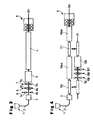
- the plant for the production of steel sheets and strips consists essentially of a continuous casting plant 1 (schematically indicated here by a mold) for a strand 2 of 30 to 250 mm thickness, preferably 30 to 130 - this thickness specification does not limit the scope of the invention - a cross-cutting device 3, a device 4 for heating or balancing the temperature, for example a Hubbalkenofen or a roller hearth furnace, and a rolling mill 5 (here schematically with two rolling stands 5a, 5b indicated ).
- the details of the rolling train (Vorgerüste, Coilbox, etc.) and adjoining the rolling mill 5 cooling devices and coiler are not shown.
- the separator can be dispensed with the separator.
- the cast slab strand 2 is divided after the deflection in the horizontal by the cross-cutting device 3, preferably in the form of a dividing shear, into sections and conveyed through the oven 4.
- the heated in the oven 4 to homogenous rolling temperature or thermally balanced slab sections are then rolled in the embodiment shown in the rolling train 5 to tapes. This process is referred to below as production line (X).
- a device for surface treatment 6 is arranged in the warm state of the respective slab section.
- the type of surface treatment is not specified here, for example, known methods such as grinding with grinding wheels, belts or stones or milling.
- the slab transport speed in the surface treatment roughly corresponds to the casting speed.
- a device for partial cooling 7 is arranged before the device for surface treatment 6 - seen in the conveying direction -.
- both the lower and upper side of the respective slab section are simultaneously cooled in a defined section by means of a two-part cooling device (parts 7a, 7b), for example by means of nozzles, which apply a cooling medium to the surface.
- the core temperature of the slabs by the partial cooling substantially unaffected. It is only a slow steady temperature drop due to the overall thermal conditions, i. the cooling after the casting process, determine.
- the surface temperature of the slabs drops to temperatures below 900 ° C, preferably to a temperature range between 500 to 900 ° C, which has an advantageous effect on the service life of the tools used for machining surface treatment.
- a homogenization of the temperatures or structural regions over the slab cross-section in the furnace 4 is ensured.
- austenitic and acid-resistant austenites which do not convert on cooling, partial cooling of the surface or parts of the surface, even at low temperatures, is unproblematic.
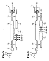
- corresponding components are provided with the same reference numerals.
- the processing means 6 are preceded by a device for surface inspection 8 in addition to a surface cooling device 7.
- This is also composed of two components 8a, 8b, in order to take in each case the top and bottom of the slabs 2 over a defined section continuously as they pass through and to detect any surface defects.
- only a selective surface processing is performed automatically in the subsequent surface treatment device 6, for example by the Only apply abrasives locally to the slab surface.
- Such an inspection is done with known types of surface analysis devices that scan the surface in a grid or in sections.
- FIG. 3 an embodiment with a descaling device 9 of two components (9a, 9b) for the simultaneous influencing of the top and bottom of the slabs 2 is shown. It is also conceivable to process the top and bottom sides or the side surfaces successively by means of correspondingly offset arrangements.
- the descaling device is - viewed in the conveying direction - in front of the inspection device 8 and this in turn arranged in front of the device for partial cooling 7.
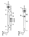
- the production line (X) of the plant consists of a continuous slab caster 1, a cross-section device 3, a cross-movable first ferry 110, a first section of the furnace 104a, a second cross-transportable ferry 111, optionally a second furnace section 104b and a second Rolling mill 5 together.
- the slab ferry which is located in the sideline (Y), is each drawn by dash-dotted lines. The transverse movement of the ferries is indicated by arrows.
- the outlet 116 of the first ferry 110 is aligned with a surface treatment complex composed of the descaling means 109 - inspection means 108, and for example a grinding machine 106 and a roller conveyor for longitudinal conveying of the thin slab section parallel to the production line (X).
- a homogenization of the temperatures across the slab cross section in preparation for the rolling process is then carried out in a second part of the roller hearth furnace 104b.
- the respective slab section passes through the conventional sequence of furnace and rolling mill, with the two transverse ferries forming part of the furnace.
- the gap resulting from the retraction of the respective slab ferry can also be closed in order to continue the method by oven sections waiting in an opposite side position Z (not shown).
- the production line (X) is composed of a cross-section 3, a first cross-pile ferry 110, a furnace 112, a second cross-sludge ferry 111 and a rolling line 5, while the side line (Y) the movable first ferry (shown in dashed line), the Surface treatment complex (106 to 109), a subsequent furnace 113 and a second movable Querbrammenfähre.
- FIG. 4 Another embodiment of the system according to FIG. 4 is shown in FIG.
- the surface treatment complex (106 to 109) is preceded by a buffer furnace 114, which receives on a surface treatment waiting slabs and ensures that they do not cool substantially.
- the plant as shown in Figure 7, combines the plant parts buffer furnace 114 and heater 115, which also allows reheating the slab sections in addition to balancing the temperatures. It is achieved that the processed slabs, which were preliminarily cooled near the surface, are brought back to the temperature required for a rolling or undergo a temperature homogenization and subjected after rolling of the slab section back into the production line (X) the rolling process.
- FIG. 8 shows the embodiment of a system for producing strips and sheets with the step of partial cooling upstream of the surface preparation within the production line (X), the surface finishing device being arranged downstream of the heating device.
- the production line (X) is after the casting machine 1 according to the optional separation device 3 in this embodiment of a heating device 204, which preferably consists of a roller hearth furnace, a surface treatment device 206 with a preceding cooling device 207 and subsequent rolling mill 5 together.
- the slab transport speed is already adapted to the required rolling transport speed. All other embodiments described in Figures 2 to 7 are also applicable to this system in a corresponding manner.
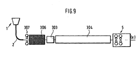
- FIG. 9 shows a system of successively arranged components casting machine 1, means for partial Cooling 307, surface treatment device 306, cross-cutting device 303, heating device 304 and a rolling mill 5.
- This embodiment has the advantage that the surface treatment does not take place on already separate slab pieces, but is integrated into the continuous process and thus Can work continuously without interruptions and adjustments to the respective slab piece.
Landscapes
- Engineering & Computer Science (AREA)
- Mechanical Engineering (AREA)
- Metal Rolling (AREA)
- Continuous Casting (AREA)
- Coating With Molten Metal (AREA)
- Heat Treatments In General, Especially Conveying And Cooling (AREA)
- Heat Treatment Of Steel (AREA)
- Preventing Corrosion Or Incrustation Of Metals (AREA)
Applications Claiming Priority (2)
| Application Number | Priority Date | Filing Date | Title |
|---|---|---|---|
| DE19953252A DE19953252A1 (de) | 1999-11-04 | 1999-11-04 | Verfahren zur Oberflächenbearbeitung eines kontinuierlich gegossenen Stahlproduktes und Einrichtung hierzu |
| DE19953252 | 1999-11-04 |
Publications (3)
| Publication Number | Publication Date |
|---|---|
| EP1097764A2 EP1097764A2 (de) | 2001-05-09 |
| EP1097764A3 EP1097764A3 (de) | 2003-08-13 |
| EP1097764B1 true EP1097764B1 (de) | 2007-10-03 |
Family
ID=7928006
Family Applications (1)
| Application Number | Title | Priority Date | Filing Date |
|---|---|---|---|
| EP00123088A Expired - Lifetime EP1097764B1 (de) | 1999-11-04 | 2000-11-02 | Verfahren zur Oberflächenbearbeitung eines kontinuierlich gegossenen Stahlproduktes und Einrichtung hierzu |
Country Status (7)
| Country | Link |
|---|---|
| US (1) | US6436205B1 (ja) |
| EP (1) | EP1097764B1 (ja) |
| JP (1) | JP4745495B2 (ja) |
| AT (1) | ATE374660T1 (ja) |
| BR (1) | BR0006775A (ja) |
| DE (2) | DE19953252A1 (ja) |
| ES (1) | ES2291163T3 (ja) |
Families Citing this family (26)
| Publication number | Priority date | Publication date | Assignee | Title |
|---|---|---|---|---|
| DE10045085C2 (de) * | 2000-09-12 | 2002-07-18 | Siemens Ag | Gießwalzanlage |
| DE10109223C1 (de) | 2001-02-26 | 2002-08-01 | Siemens Ag | Verfahren zum Betreiben einer Gießwalzanlage |
| DE10138794A1 (de) * | 2001-08-07 | 2003-02-27 | Sms Demag Ag | Verfahren und Anlage zur Produktion von Flach- und Langprodukten |
| DE10252246A1 (de) * | 2002-11-07 | 2004-05-27 | Sms Demag Ag | Verfahren und Anlage zur Oberflächenbehandlung innerhalb einer Stranggießanlage |
| DE102006005635A1 (de) * | 2006-02-08 | 2007-08-09 | Sms Demag Ag | Rollenherdofen zum Aufheizen und/oder Temperaturausgleichen von Stranggiessprodukten aus Stahl oder Stahllegierung und dessen Anordnung vor einer Warmband-Fertigwalzstrasse |
| JP4816130B2 (ja) | 2006-02-22 | 2011-11-16 | Jfeスチール株式会社 | 鋼の連続鋳造鋳片の製造方法および鋳片の表層欠陥手入システム。 |
| DE102007022932A1 (de) | 2006-05-26 | 2007-12-20 | Sms Demag Ag | Verfahren und Vorrichtung zum Herstellen eines Metallbandes durch Stranggießen |
| DE102007022931A1 (de) | 2006-05-26 | 2007-11-29 | Sms Demag Ag | Verfahren und Vorrichtung zum Herstellen eines Metallbandes durch Stranggießen |
| DE102007022928A1 (de) * | 2006-05-26 | 2007-12-13 | Sms Demag Ag | Vorrichtung zum Herstellen eines Metallbandes durch Stranggießen |
| DE102007022927A1 (de) * | 2006-05-26 | 2007-12-20 | Sms Demag Ag | Vorrichtung und Verfahren zum Herstellen eines Metallbandes durch Stranggießen |
| DE102007022929A1 (de) * | 2006-05-26 | 2007-12-20 | Sms Demag Ag | Vorrichtung und Verfahren zum Herstellen eines Metallbandes durch Stranggießen |
| DE102007005015A1 (de) | 2006-06-26 | 2008-01-03 | Sms Demag Ag | Verfahren und Anlage zur Herstellung von Warmband-Walzgut aus Siliziumstahl auf der Basis von Dünnbrammen |
| KR100812065B1 (ko) * | 2006-11-23 | 2008-03-07 | 주식회사 포스코 | 스테인레스강 열간 및 냉간 압연재의 면거침 결함 개선방법 |
| DE102007020240A1 (de) * | 2007-04-24 | 2008-10-30 | Sms Demag Ag | Verfahren zur Erkennung und Klassifizierung von Oberflächenfehlern auf stranggegossenen Brammen |
| JP4867789B2 (ja) * | 2007-05-24 | 2012-02-01 | Jfeスチール株式会社 | 熱間スラブの表層部手入れ方法及び熱延鋼材の製造方法 |
| EP2174728B1 (en) * | 2007-07-04 | 2011-08-31 | Baoshan Iron & Steel Co., Ltd. | A high efficient, energy-saving process of continuous casting-rolling of the strip steels |
| DE102009019721B4 (de) * | 2009-05-05 | 2011-09-01 | Hoerbiger Automatisierungstechnik Holding Gmbh | Hydraulisches System |
| WO2013159786A1 (de) * | 2012-04-24 | 2013-10-31 | Gaydoul Juergen | Verfahren und anlage zum nachbehandeln eines gegossenen und/oder warm gewalzten stahlproduktes |
| KR102297929B1 (ko) | 2013-03-15 | 2021-09-06 | 마테리온 코포레이션 | 균일한 결정 입도의 열간 가공된 스피노달 합금 |
| CN104056865B (zh) * | 2013-03-19 | 2017-02-22 | 宝山钢铁股份有限公司 | 一种钢板表面处理方法及其装置 |
| JP6154708B2 (ja) * | 2013-09-27 | 2017-06-28 | 日新製鋼株式会社 | 連続鋳造方法 |
| CN106734575B (zh) * | 2017-01-23 | 2019-07-23 | 上海众达汽车冲压件有限公司 | 一种冲压式模具生产线的加工工艺 |
| KR101998966B1 (ko) | 2017-11-03 | 2019-07-10 | 주식회사 포스코 | 연주압연장치 및 연주압연방법 |
| DE102020205077A1 (de) * | 2019-09-23 | 2021-03-25 | Sms Group Gmbh | Vorrichtung und Verfahren zur Herstellung und Weiterbehandlung von Brammen |
| DE102021211339A1 (de) * | 2020-10-13 | 2022-04-14 | Sms Group Gmbh | Vorrichtung und Verfahren zur Herstellung von warmgewalzten Metallbändern |
| WO2023186471A1 (de) * | 2022-03-29 | 2023-10-05 | Sms Group Gmbh | GIEßWALZANLAGE UND VERFAHREN ZU DEREN BETRIEB |
Family Cites Families (7)
| Publication number | Priority date | Publication date | Assignee | Title |
|---|---|---|---|---|
| FR1450829A (fr) * | 1965-07-16 | 1966-06-24 | Etude Rationnelle Des Probleme | Procédé de fabrication directe et continue de produits métallurgiques |
| US3503161A (en) * | 1967-09-29 | 1970-03-31 | Cayuga Machine & Fabrication C | Method of treating a continuously cast billet |
| JPS5036594B1 (ja) * | 1970-06-19 | 1975-11-26 | ||
| DE3037571A1 (de) | 1980-10-04 | 1982-04-22 | Thyssen Edelstahlwerke AG, 4000 Düsseldorf | Verfahren zum mechanischen abtragen von material von stahlstrangguss-oberflaechen und schleifvorrichtung |
| SE462078B (sv) | 1988-09-16 | 1990-05-07 | Tom Nordquist | Saett foer bandslipning av aemnen av metaller och metallegeringar |
| JPH05320771A (ja) * | 1992-05-15 | 1993-12-03 | Kawasaki Steel Corp | 冷間圧延用ステンレス予備処理鋼帯の製造方法及び装置 |
| EP0880023A1 (de) * | 1997-05-23 | 1998-11-25 | Siemag Transplan Gmbh | Verfahren und Vorrichtung zur automatischen Detektion von Oberflächenfehlern beim kontinuierlichen mechanischem Abtragen von Material von Stranggiessprodukten |
-
1999
- 1999-11-04 DE DE19953252A patent/DE19953252A1/de not_active Withdrawn
-
2000
- 2000-10-31 BR BR0006775-0A patent/BR0006775A/pt not_active IP Right Cessation
- 2000-11-01 US US09/704,220 patent/US6436205B1/en not_active Expired - Fee Related
- 2000-11-02 DE DE50014689T patent/DE50014689D1/de not_active Expired - Lifetime
- 2000-11-02 EP EP00123088A patent/EP1097764B1/de not_active Expired - Lifetime
- 2000-11-02 JP JP2000336052A patent/JP4745495B2/ja not_active Expired - Fee Related
- 2000-11-02 AT AT00123088T patent/ATE374660T1/de active
- 2000-11-02 ES ES00123088T patent/ES2291163T3/es not_active Expired - Lifetime
Also Published As
| Publication number | Publication date |
|---|---|
| BR0006775A (pt) | 2001-07-31 |
| JP4745495B2 (ja) | 2011-08-10 |
| EP1097764A2 (de) | 2001-05-09 |
| DE19953252A1 (de) | 2001-05-10 |
| ES2291163T3 (es) | 2008-03-01 |
| US6436205B1 (en) | 2002-08-20 |
| JP2001170745A (ja) | 2001-06-26 |
| EP1097764A3 (de) | 2003-08-13 |
| DE50014689D1 (de) | 2007-11-15 |
| ATE374660T1 (de) | 2007-10-15 |
Similar Documents
| Publication | Publication Date | Title |
|---|---|---|
| EP1097764B1 (de) | Verfahren zur Oberflächenbearbeitung eines kontinuierlich gegossenen Stahlproduktes und Einrichtung hierzu | |
| EP3541562B1 (de) | Verfahren und vorrichtung zur herstellung eines kontinuierlichen bandförmigen verbundmaterials | |
| EP1318876B1 (de) | Verfahren und anlage zum herstellen von bändern und blechen aus stahl | |
| EP1781428B1 (de) | Verfahren und vorrichtung zum herstellen von metallbändern | |
| WO2007137740A1 (de) | Verfahren und vorrichtung zum herstellen eines metallbandes durch stranggiessen | |
| EP0867239B1 (de) | Verfahren und Anlage zum Auswalzen von Warmbreitband aus stranggegossenen Brammen | |
| DE3149647C2 (ja) | ||
| DE102009060256A1 (de) | Verfahren zum Warmwalzen einer Bramme und Warmwalzwerk | |
| DE4234454A1 (de) | Verfahren und Anlage zur Herstellung von warmgewalzten Bändern oder Profilen aus stranggegossenem Vormaterial | |
| DE68923148T2 (de) | Warmwalzanlage und Verfahren zum Warmwalzen einer Bramme. | |
| DE4009861C2 (de) | Verfahren zur Herstellung von warmgewalztem Stangenmaterial wie Feinstahl oder Draht und Anlage zur Durchführung des Verfahrens | |
| EP0808672B1 (de) | Verfahren und Anlage zur Herstellung von Edelstahl- oder Kohlenstoffstahlblech aus durch Strangguss erzeugten Dünnbrammen | |
| DE102008039140A1 (de) | Verfahren und Vorrichtung zum Erzeugen eines Magnesiumbands | |
| AT405033B (de) | Verfahren zur herstellung von stranggegossenen gussstücken und anlage zur durchführung des verfahrens | |
| DE10134075C2 (de) | Verfahren zum Herstellen von Metallband, insbesondere von Stahlband, durch Gießwalzen | |
| EP2032286B1 (de) | Vorrichtung zum herstellen eines metalbandes durch stranggiessen | |
| DE102022208817A1 (de) | Gießwalzanlage und Verfahren zu deren Betrieb | |
| WO2023186471A1 (de) | GIEßWALZANLAGE UND VERFAHREN ZU DEREN BETRIEB | |
| DE3306372A1 (de) | Verfahren zur herstellung von stahlblechen oder -platten | |
| DE102021211339A1 (de) | Vorrichtung und Verfahren zur Herstellung von warmgewalzten Metallbändern | |
| DE10252246A1 (de) | Verfahren und Anlage zur Oberflächenbehandlung innerhalb einer Stranggießanlage | |
| EP3725450A2 (de) | Verfahren und vorrichtung zur herstellung eines mehrschichtigen verbundmaterials | |
| WO2007137759A1 (de) | Vorrichtung und verfahren zum herstellen eines metallbandes durch stranggiessen |
Legal Events
| Date | Code | Title | Description |
|---|---|---|---|
| PUAI | Public reference made under article 153(3) epc to a published international application that has entered the european phase |
Free format text: ORIGINAL CODE: 0009012 |
|
| 17P | Request for examination filed |
Effective date: 20001107 |
|
| AK | Designated contracting states |
Kind code of ref document: A2 Designated state(s): AT BE CH CY DE DK ES FI FR GB GR IE IT LI LU MC NL PT SE |
|
| AX | Request for extension of the european patent |
Free format text: AL;LT;LV;MK;RO;SI |
|
| PUAL | Search report despatched |
Free format text: ORIGINAL CODE: 0009013 |
|
| AK | Designated contracting states |
Designated state(s): AT BE CH CY DE DK ES FI FR GB GR IE IT LI LU MC NL PT SE |
|
| AX | Request for extension of the european patent |
Extension state: AL LT LV MK RO SI |
|
| AKX | Designation fees paid |
Designated state(s): AT BE CH CY DE DK ES FI FR GB GR IE IT LI LU MC NL PT SE |
|
| 17Q | First examination report despatched |
Effective date: 20041230 |
|
| APBN | Date of receipt of notice of appeal recorded |
Free format text: ORIGINAL CODE: EPIDOSNNOA2E |
|
| APBR | Date of receipt of statement of grounds of appeal recorded |
Free format text: ORIGINAL CODE: EPIDOSNNOA3E |
|
| APBV | Interlocutory revision of appeal recorded |
Free format text: ORIGINAL CODE: EPIDOSNIRAPE |
|
| GRAP | Despatch of communication of intention to grant a patent |
Free format text: ORIGINAL CODE: EPIDOSNIGR1 |
|
| GRAS | Grant fee paid |
Free format text: ORIGINAL CODE: EPIDOSNIGR3 |
|
| GRAA | (expected) grant |
Free format text: ORIGINAL CODE: 0009210 |
|
| AK | Designated contracting states |
Kind code of ref document: B1 Designated state(s): AT BE CH CY DE DK ES FI FR GB GR IE IT LI LU MC NL PT SE |
|
| REG | Reference to a national code |
Ref country code: GB Ref legal event code: FG4D Free format text: NOT ENGLISH |
|
| REG | Reference to a national code |
Ref country code: CH Ref legal event code: EP |
|
| REG | Reference to a national code |
Ref country code: IE Ref legal event code: FG4D Free format text: LANGUAGE OF EP DOCUMENT: GERMAN |
|
| REF | Corresponds to: |
Ref document number: 50014689 Country of ref document: DE Date of ref document: 20071115 Kind code of ref document: P |
|
| REG | Reference to a national code |
Ref country code: SE Ref legal event code: TRGR |
|
| GBT | Gb: translation of ep patent filed (gb section 77(6)(a)/1977) |
Effective date: 20080113 |
|
| REG | Reference to a national code |
Ref country code: ES Ref legal event code: FG2A Ref document number: 2291163 Country of ref document: ES Kind code of ref document: T3 |
|
| ET | Fr: translation filed | ||
| PG25 | Lapsed in a contracting state [announced via postgrant information from national office to epo] |
Ref country code: PT Free format text: LAPSE BECAUSE OF FAILURE TO SUBMIT A TRANSLATION OF THE DESCRIPTION OR TO PAY THE FEE WITHIN THE PRESCRIBED TIME-LIMIT Effective date: 20080303 |
|
| BERE | Be: lapsed |
Owner name: MS DEMAG AG Effective date: 20071130 |
|
| REG | Reference to a national code |
Ref country code: IE Ref legal event code: FD4D |
|
| PG25 | Lapsed in a contracting state [announced via postgrant information from national office to epo] |
Ref country code: MC Free format text: LAPSE BECAUSE OF NON-PAYMENT OF DUE FEES Effective date: 20071130 |
|
| PG25 | Lapsed in a contracting state [announced via postgrant information from national office to epo] |
Ref country code: DK Free format text: LAPSE BECAUSE OF FAILURE TO SUBMIT A TRANSLATION OF THE DESCRIPTION OR TO PAY THE FEE WITHIN THE PRESCRIBED TIME-LIMIT Effective date: 20071003 Ref country code: LI Free format text: LAPSE BECAUSE OF NON-PAYMENT OF DUE FEES Effective date: 20071130 Ref country code: CH Free format text: LAPSE BECAUSE OF NON-PAYMENT OF DUE FEES Effective date: 20071130 |
|
| REG | Reference to a national code |
Ref country code: CH Ref legal event code: PL |
|
| PLBE | No opposition filed within time limit |
Free format text: ORIGINAL CODE: 0009261 |
|
| STAA | Information on the status of an ep patent application or granted ep patent |
Free format text: STATUS: NO OPPOSITION FILED WITHIN TIME LIMIT |
|
| 26N | No opposition filed |
Effective date: 20080704 |
|
| PG25 | Lapsed in a contracting state [announced via postgrant information from national office to epo] |
Ref country code: BE Free format text: LAPSE BECAUSE OF NON-PAYMENT OF DUE FEES Effective date: 20071130 |
|
| PG25 | Lapsed in a contracting state [announced via postgrant information from national office to epo] |
Ref country code: IE Free format text: LAPSE BECAUSE OF FAILURE TO SUBMIT A TRANSLATION OF THE DESCRIPTION OR TO PAY THE FEE WITHIN THE PRESCRIBED TIME-LIMIT Effective date: 20071003 |
|
| PG25 | Lapsed in a contracting state [announced via postgrant information from national office to epo] |
Ref country code: GR Free format text: LAPSE BECAUSE OF FAILURE TO SUBMIT A TRANSLATION OF THE DESCRIPTION OR TO PAY THE FEE WITHIN THE PRESCRIBED TIME-LIMIT Effective date: 20080104 |
|
| PG25 | Lapsed in a contracting state [announced via postgrant information from national office to epo] |
Ref country code: FI Free format text: LAPSE BECAUSE OF FAILURE TO SUBMIT A TRANSLATION OF THE DESCRIPTION OR TO PAY THE FEE WITHIN THE PRESCRIBED TIME-LIMIT Effective date: 20071003 |
|
| PG25 | Lapsed in a contracting state [announced via postgrant information from national office to epo] |
Ref country code: CY Free format text: LAPSE BECAUSE OF FAILURE TO SUBMIT A TRANSLATION OF THE DESCRIPTION OR TO PAY THE FEE WITHIN THE PRESCRIBED TIME-LIMIT Effective date: 20071003 |
|
| PG25 | Lapsed in a contracting state [announced via postgrant information from national office to epo] |
Ref country code: LU Free format text: LAPSE BECAUSE OF NON-PAYMENT OF DUE FEES Effective date: 20071102 |
|
| PGFP | Annual fee paid to national office [announced via postgrant information from national office to epo] |
Ref country code: SE Payment date: 20091112 Year of fee payment: 10 Ref country code: ES Payment date: 20091123 Year of fee payment: 10 |
|
| PGFP | Annual fee paid to national office [announced via postgrant information from national office to epo] |
Ref country code: NL Payment date: 20091112 Year of fee payment: 10 |
|
| PGFP | Annual fee paid to national office [announced via postgrant information from national office to epo] |
Ref country code: FR Payment date: 20091201 Year of fee payment: 10 Ref country code: GB Payment date: 20091119 Year of fee payment: 10 |
|
| REG | Reference to a national code |
Ref country code: NL Ref legal event code: V1 Effective date: 20110601 |
|
| REG | Reference to a national code |
Ref country code: SE Ref legal event code: EUG |
|
| GBPC | Gb: european patent ceased through non-payment of renewal fee |
Effective date: 20101102 |
|
| REG | Reference to a national code |
Ref country code: FR Ref legal event code: ST Effective date: 20110801 |
|
| PG25 | Lapsed in a contracting state [announced via postgrant information from national office to epo] |
Ref country code: NL Free format text: LAPSE BECAUSE OF NON-PAYMENT OF DUE FEES Effective date: 20110601 |
|
| PG25 | Lapsed in a contracting state [announced via postgrant information from national office to epo] |
Ref country code: SE Free format text: LAPSE BECAUSE OF NON-PAYMENT OF DUE FEES Effective date: 20101103 |
|
| PG25 | Lapsed in a contracting state [announced via postgrant information from national office to epo] |
Ref country code: FR Free format text: LAPSE BECAUSE OF NON-PAYMENT OF DUE FEES Effective date: 20101130 |
|
| PG25 | Lapsed in a contracting state [announced via postgrant information from national office to epo] |
Ref country code: GB Free format text: LAPSE BECAUSE OF NON-PAYMENT OF DUE FEES Effective date: 20101102 |
|
| REG | Reference to a national code |
Ref country code: ES Ref legal event code: FD2A Effective date: 20120510 |
|
| PG25 | Lapsed in a contracting state [announced via postgrant information from national office to epo] |
Ref country code: ES Free format text: LAPSE BECAUSE OF NON-PAYMENT OF DUE FEES Effective date: 20101103 |
|
| PGFP | Annual fee paid to national office [announced via postgrant information from national office to epo] |
Ref country code: DE Payment date: 20121121 Year of fee payment: 13 |
|
| PGFP | Annual fee paid to national office [announced via postgrant information from national office to epo] |
Ref country code: IT Payment date: 20121126 Year of fee payment: 13 |
|
| PGFP | Annual fee paid to national office [announced via postgrant information from national office to epo] |
Ref country code: AT Payment date: 20121113 Year of fee payment: 13 |
|
| REG | Reference to a national code |
Ref country code: DE Ref legal event code: R119 Ref document number: 50014689 Country of ref document: DE |
|
| REG | Reference to a national code |
Ref country code: AT Ref legal event code: MM01 Ref document number: 374660 Country of ref document: AT Kind code of ref document: T Effective date: 20131102 |
|
| PG25 | Lapsed in a contracting state [announced via postgrant information from national office to epo] |
Ref country code: IT Free format text: LAPSE BECAUSE OF NON-PAYMENT OF DUE FEES Effective date: 20131102 Ref country code: AT Free format text: LAPSE BECAUSE OF NON-PAYMENT OF DUE FEES Effective date: 20131102 |
|
| REG | Reference to a national code |
Ref country code: DE Ref legal event code: R119 Ref document number: 50014689 Country of ref document: DE Effective date: 20140603 |
|
| PG25 | Lapsed in a contracting state [announced via postgrant information from national office to epo] |
Ref country code: DE Free format text: LAPSE BECAUSE OF NON-PAYMENT OF DUE FEES Effective date: 20140603 |