EP1097656B1 - Table-type having at least one foldable foot or underframe - Google Patents
Table-type having at least one foldable foot or underframe Download PDFInfo
- Publication number
- EP1097656B1 EP1097656B1 EP00460059A EP00460059A EP1097656B1 EP 1097656 B1 EP1097656 B1 EP 1097656B1 EP 00460059 A EP00460059 A EP 00460059A EP 00460059 A EP00460059 A EP 00460059A EP 1097656 B1 EP1097656 B1 EP 1097656B1
- Authority
- EP
- European Patent Office
- Prior art keywords
- foot
- base
- table according
- unfolded
- folded
- Prior art date
- Legal status (The legal status is an assumption and is not a legal conclusion. Google has not performed a legal analysis and makes no representation as to the accuracy of the status listed.)
- Expired - Lifetime
Links
Images

Classifications
-
- A—HUMAN NECESSITIES
- A47—FURNITURE; DOMESTIC ARTICLES OR APPLIANCES; COFFEE MILLS; SPICE MILLS; SUCTION CLEANERS IN GENERAL
- A47B—TABLES; DESKS; OFFICE FURNITURE; CABINETS; DRAWERS; GENERAL DETAILS OF FURNITURE
- A47B3/00—Folding or stowable tables
- A47B3/08—Folding or stowable tables with legs pivoted to top or underframe
- A47B3/0809—Folding or stowable tables with legs pivoted to top or underframe with elastic locking means
- A47B3/0815—Folding or stowable tables with legs pivoted to top or underframe with elastic locking means the resilient force of the elastic locking means acting in a direction perpendicular to the axis of rotation of the leg
-
- A—HUMAN NECESSITIES
- A47—FURNITURE; DOMESTIC ARTICLES OR APPLIANCES; COFFEE MILLS; SPICE MILLS; SUCTION CLEANERS IN GENERAL
- A47B—TABLES; DESKS; OFFICE FURNITURE; CABINETS; DRAWERS; GENERAL DETAILS OF FURNITURE
- A47B3/00—Folding or stowable tables
- A47B3/08—Folding or stowable tables with legs pivoted to top or underframe
- A47B2003/0824—Folding or stowable tables with legs pivoted to top or underframe the table legs being individually collapsible against the underside of the table top
Definitions
- the present invention relates to a table of the type having at least one foot or foldable frame mounted on a frame.
- a table can have various applications and, in particular, that of supporting tools such as saws Circular used in the field of building.
- Tables are known whose table legs are collapsible to obtain a less space of said tables during their transport and to facilitate their set up on construction sites.
- US-A-4,144,822 discloses a table whose legs are foldable.
- Known folding tables usually have feet articulated individually or in pairs around an axis of rotation, so that said feet can take a folded position under said table frame and a unfolded position where said feet support said frame. Blocking in the folded position or unfolded by means of a locking device which is generally constituted a lock blocking the foot or the pair of feet in one or the other position. This lock is unlockable by operating a member of said locking device.
- the object of the invention is therefore to propose a table of the type which comprises at least one foot or folding base, the maneuver for blocking and unlocking is easier.
- the table whose legs are foldable is remarkable in that it includes a blocking device designed to allow the sliding of each foot or footing to allow its blocking and unblocking in each its folded and unfolded positions.
- said foot or to move from its folded position to its unfolded position and vice versa is articulated around an axis;
- said locking device comprises a pin for penetrate each of two grooves in order to block said foot or base in each of said positions folded and unfolded;
- the locking device comprises also a light provided to allow the sliding of the axis towards one and the other throat
- the pion is designed to slide on the profile of a cam disposed between the first and second grooves when said foot or base moves from its folded position to its position unfolded and vice versa .
- the invention comprises a return means acting on said foot or base so as to hold the piece in the grooves or against the cam.
- said device for blocking comprises first and second stops provided for respectively serving stopper to sidewalls of a foot or footing when said foot or footing is in its unfolded position.
- the first stop is intended to limit the angular displacement of a foot or foot in its folded position.
- the first stop extends to the normal axis projected on the side wall, to serve as a point tilting of a foot or base during its folding.
- the table is provided at least one handle or a set of wheels.
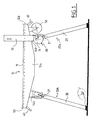
- the table shown in FIG. 1 consists essentially of a chassis 10 provided with a plate 11, two legs 20a provided to be able to take a folded position under the frame 10 and an unfolded position where they support said chassis 10.
- the plate 11 is extended on its lateral sides by two cheeks of stiffening 12a and 12b (only the cheek 12a is visible in Fig. 1) respectively for example for fixing a disc saw (not shown) by through two stiffening cheeks 12a and 12b (only the cheek 12a is visible in FIG. 1) and a tool attachment device 13.
- a handle 40 is attached to each of the longitudinal sides 12c and 12d of the chassis 10.
- a set of wheels 50 is mounted under the plate 11 near one longitudinal sides 12c or 12d.
- the frame 10 is supported by two legs 20a and 20b formed of two feet 20 secured to one another by means of a spacer 21.
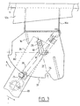
- Each foot 20 is mounted in a locking device 30 constituted, in the embodiment shown, a flange 31 fixed to each of the two ends of two sleepers 14a or 14b themselves transversely fixed under the plateau 11 between the cheeks 12a and 12b.
- the wall of the flange 31 has a light 32 which has a L shape of main axis A1 and secondary axis A2 and whose ends have a form of semicircle.
- an axis 23 which is mounted in a front wall 24 of said foot 20 can slide in said light 32.
- the axis 23 is positioned at a short distance from the upper end of the foot 20, in a median plane to the front wall 24.
- Said front wall 24 of the foot 20 is provided to contact the flange 31, preferably with its inner face as this is shown in FIG. 2.
- the flange 31 is also delimited at one of its edges by a cam 33 whose the profile has a shape of a portion of a circle.
- the cam 33 is framed, of a part, by a first groove 34 of semicylindrical section whose center is located in the extension of the main axis A1 of the light 32 and, on the other hand, by a second groove 35 of semi-cylindrical section whose center is located in the extension of the secondary axis A2 of the light 32.
- a pin 25 is also mounted in a median plane of the foot 20 so as to away from the axis 23 by a distance equal to the game close to the distance between the axis of the high end of the light, and the axis of the first groove 34 of the same flange.
- the foot 20 or the base 20a is immobilized and locked in one of its two positions: its folded position and unfolded position.
- the pin 25 can slide along the profile of said cam 33.
- a first stop 36 is attached to the wall of the flange 31 receiving the front wall 24 of the foot 20, in this case the inner wall of said flange in FIG. 2. It is disposed between the second groove 35 and the light 32 so that it can come into contact with a side wall 26 of the foot 20, when said foot 20 is in an unfolded position as shown in FIG. 2.
- Said abutment 36 also extends to the normal of the axis 23 projected on the side wall 26, that is to say not far from the upper end of the foot 20, to serve tipping point to said foot 20 during folding.
- a second stop 37 is attached to the inner wall of the flange 31. It is arranged so that it can come into contact with a side wall 27 opposite to the side wall 26 of the foot 20, when said foot is maneuvered in position unfolded as shown in FIG. 2.
- a return means 28 which is, for example, a tension spring as this is shown in FIG. 2, is installed so that each peg 25 exerts a restoring force on the foot 20 or the base 20a so as to hold the pawn 25 located either inside the groove 34 or inside the groove 25, or the along the profile of the cam 33.
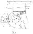
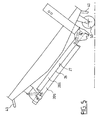
- the return means is for example mounted between a cross member 14a or 14b and the spacer 21 of a base 20a or 20b. It is further positioned so that the axis connecting its two attachment points passes either on one side of the axis 23 when the foot 20 is in the folded position, as can be seen in FIG. 4, on the other side of the axis 23 when the foot 20 is in the unfolded position as can be seen in FIG. 2.
- FIG. 2 the table of the invention is shown in working position, that is to say with his feet 20 unfolded.
- each of the legs 20 thus leaves the first groove 34 of a flange 31, which allows rotation to the base 20a around each axis 23. Then, the user rotates the base 20a so that each pin 25 can slide along the profile of the cam 33 of a flange 31 as indicates the arrow C in FIG. 3.
- the return means 28 keeps in contact the pin 25 of each of the legs 20 against the profile of the cam 33 of a flange 31.
- the side wall 26 of each of the feet 20 then comes into contact with the first stop 36 of a flange 31, which allows the shaft 23 of each of the legs 20 to slide along the main axis A1 of the light 32 of a flange 31.
- each of the legs 20 continues its movement on the profile of the cam 33 of a flange 31 so that the axis connecting the two attachment points of the return means 28 crosses each of the axes 23 and passes on the other side of said axes, this which reduces the maneuvering force required to fold the base 20a.
- the folding table can be lifted by its handles 40. It can also be moved by a handle 40, the table resting on the ground on its casters 50.
- the user exerts traction on the base 20a in the direction indicated by the arrow D of FIG. 4. It can for example exert this traction in pulling on one of the legs 20 of the base 20a, or exert a traction on the spacer 21 connecting the base 20a.
- the pin 25 of each of the legs 20 then leaves the second 35 of a flange 31, while the axis 23 of each of the feet 20 slides along of the secondary axis A2 of the light 32 of a flange 31. Then, the user leads in rotation the base 20a about the axes 23, as indicated by the arrow E of FIG. 3.
- the axis connecting the two attachment points of the return means 28 intersects a once again each axis 23 and passes on the other side of said axes, which reduces the maneuvering force necessary to unfold the base 20a.
- each of the feet 20 comes into contact with it. moment with the second stop 37 of a flange 31, which further limits the angular displacement of each of the feet 20.
- a third wall of a foot the wall front 24 is in contact with a flange 31.
- three walls 26, 27 and 24 of each of the feet 20 is in contact with a flange 31 when said foot is in its unfolded position. This results in a high rigidity of the connection of the chassis 10 of the table and his feet 20.
Abstract
Description
La présente invention concerne une table du type ayant au moins un pied ou piétement repliable monté sur un châssis. Une telle table peut avoir diverses applications et, en particulier, celle de supporter un outillage, tel qu'une scie circulaire utilisée dans le domaine du bâtiment.The present invention relates to a table of the type having at least one foot or foldable frame mounted on a frame. Such a table can have various applications and, in particular, that of supporting tools such as saws Circular used in the field of building.
Lors de la construction ou de la réfection d'un bâtiment, il est souvent nécessaire de transporter d'un chantier à l'autre ou d'un endroit à l'autre sur un même chantier des tables de travail, par exemple équipées d'outillages tels que des scies circulaire pour matériaux de construction tels que du carrelage ou des parpaings. Ces tables doivent pouvoir être mises en place rapidement sans nécessiter l'utilisation de clefs ou autres outils spécifiques.When building or repairing a building, it is often necessary to transport from one site to another or from one place to another on the same construction of work tables, for example equipped with tools such as saws circular for building materials such as tiling or blocks. These tables must be able to be put in place quickly without requiring the use of keys or other specific tools.
On connaít des tables dont les pieds de table sont repliables pour obtenir un encombrement moindre desdites tables lors de leur transport et pour faciliter leur mise en place sur les chantiers. Le document US-A-4 144 822 décrit une table dont les pieds sont repliables.Tables are known whose table legs are collapsible to obtain a less space of said tables during their transport and to facilitate their set up on construction sites. US-A-4,144,822 discloses a table whose legs are foldable.
Les tables à pieds repliables connues comportent généralement des pieds articulés individuellement ou par paire autour d'un axe de rotation, si bien que lesdits pieds peuvent prendre une position repliée sous ledit châssis de la table et une position dépliée où lesdits pieds supportent ledit châssis. Le blocage en position pliée ou dépliée se font grâce à un dispositif de blocage qui est généralement constitué d'un verrou bloquant le pied ou la paire de pieds dans l'une ou l'autre position. Ce verrou est déblocable en manoeuvrant un organe dudit dispositif de blocage. Known folding tables usually have feet articulated individually or in pairs around an axis of rotation, so that said feet can take a folded position under said table frame and a unfolded position where said feet support said frame. Blocking in the folded position or unfolded by means of a locking device which is generally constituted a lock blocking the foot or the pair of feet in one or the other position. This lock is unlockable by operating a member of said locking device.
Le problème rencontré par de telles tables est que le dispositif de blocage n'est pas nécessairement facilement accessible et il en résulte une mise en place parfois longue et pas toujours aisée.The problem encountered by such tables is that the blocking device is not necessarily easily accessible and the result is sometimes long and not always easy.
Le but de l'invention est donc de proposer une table du type qui comporte au moins un pied ou piétement repliable dont la manoeuvre pour le blocage et le déblocage est plus facile.The object of the invention is therefore to propose a table of the type which comprises at least one foot or folding base, the maneuver for blocking and unlocking is easier.
A cet effet, la table dont ses pieds sont repliables est remarquable en ce qu'elle comporte un dispositif de blocage prévu pour permettre le coulissement de chaque pied ou piétement afin d'autoriser son blocage et son déblocage dans chacune de ses positions repliée et dépliée.For this purpose, the table whose legs are foldable is remarkable in that it includes a blocking device designed to allow the sliding of each foot or footing to allow its blocking and unblocking in each its folded and unfolded positions.
Ainsi, le déblocage et le pliage des pieds est réalisé aisément.Thus, the unlocking and folding of the feet is achieved easily.
Selon une autre caractéristique de la table de l'invention, ledit pied ou piétement, pour passer de sa position repliée à sa position dépliée et vice versa, est articulé autour d'un axe; ledit dispositif de blocage comporte un pion destiné à pénétrer dans chacune de deux gorges afin de bloquer ledit pied ou piétement dans chacune desdites positions repliée et dépliée; le dispositif de blocage comporte également une lumière prévue pour permettre le coulissement de l'axe en direction de l'une et l'autre gorgeAccording to another characteristic of the table of the invention, said foot or to move from its folded position to its unfolded position and vice versa, is articulated around an axis; said locking device comprises a pin for penetrate each of two grooves in order to block said foot or base in each of said positions folded and unfolded; the locking device comprises also a light provided to allow the sliding of the axis towards one and the other throat
Selon une autre caractéristique de la table de l'invention, que le pion est prévu pour glisser sur le profil d'une came disposée entre les première et seconde gorges lorsque ledit pied ou piétement passe de sa position repliée à sa position dépliée et vice et versa..According to another characteristic of the table of the invention, the pion is designed to slide on the profile of a cam disposed between the first and second grooves when said foot or base moves from its folded position to its position unfolded and vice versa ..
Selon une autre caractéristique de la table l'invention, qu'elle comprend un moyen de rappel agissant sur ledit pied ou piétement de manière à maintenir le pion dans les gorges ou contre la came.According to another characteristic of the table the invention, that it comprises a return means acting on said foot or base so as to hold the piece in the grooves or against the cam.
Selon une autre caractéristique de la table de l'invention, ledit dispositif de blocage comporte une première et seconde butées prévues pour respectivement servir de butée à des parois latérales d'un pied ou piétement lorsque ledit pied ou piétement est dans sa position dépliée.According to another characteristic of the table of the invention, said device for blocking comprises first and second stops provided for respectively serving stopper to sidewalls of a foot or footing when said foot or footing is in its unfolded position.
Selon une autre caractéristique de la table de l'invention, la première butée est prévue pour limiter le déplacement angulaire d'un pied ou d'un piétement dans sa position repliée. According to another characteristic of the table of the invention, the first stop is intended to limit the angular displacement of a foot or foot in its folded position.
Selon une autre caractéristique de la table de l'invention, la première butée s'étend jusqu'à la normale de l'axe projetée sur la paroi latérale, pour servir de point de basculement d'un pied ou piétement lors de son pliage.According to another characteristic of the table of the invention, the first stop extends to the normal axis projected on the side wall, to serve as a point tilting of a foot or base during its folding.
Selon une autre caractéristique de la table de l'invention, la table est munie d'au moins une poignée ou d'un jeu de roulettes.According to another characteristic of the table of the invention, the table is provided at least one handle or a set of wheels.
Les caractéristiques de l'invention mentionnées ci-dessus, ainsi que d'autres,
apparaítront plus clairement à la lecture de la description suivante d'un exemple de
réalisation, ladite description étant faite en relation avec les dessins joints, parmi
lesquels:
La table représentée à la Fig. 1 est essentiellement constituée d'un châssis 10
pourvu d'un plateau 11, de deux piétements 20a prévus pour pouvoir prendre une
position repliée sous le châssis 10 et une position dépliée où ils supportent ledit
châssis 10.The table shown in FIG. 1 consists essentially of a
Le plateau 11 est prolongé sur ses côtés latéraux par deux joues de
rigidification 12a et 12b (seule la joue 12a est visible à la Fig. 1) respectivement
destinés par exemple à la fixation d'une scie à disque (non représentée) par
l'intermédiaire de deux joues de rigidification 12a et 12b (seule la joue 12a est visible
à la Fig. 1) et d'un dispositif de fixation d'outillage 13.The
Une poignée 40 est fixée à chacun des côtés longitudinaux 12c et 12d du
châssis 10. Un jeu de roulettes 50 est montée sous le plateau 11 à proximité de l'un
des côtés longitudinaux 12c ou 12d.A
Le châssis 10 est supporté par deux piétements 20a et 20b formés de deux
pieds 20 solidarisés l'un à l'autre au moyen d'une entretoise 21. The
Chaque pied 20 est monté dans un dispositif de blocage 30 constitué, dans
l'exemple de réalisation représenté, d'un flasque 31 fixé à chacune des deux
extrémités de deux traverses 14a ou 14b elles-mêmes fixées transversalement sous le
plateau 11 entre les joues 12a et 12b.Each
A la Fig. 2, la paroi du flasque 31 comporte une lumière 32 qui présente une
forme de L d'axe principal A1 et d'axe secondaire A2 et dont les extrémités de la ont
une forme de demi-cercle.In FIG. 2, the wall of the
Lorsque l'on manoeuvre le pied 20 pour le plier ou le déplier, un axe 23 qui
est monté dans une paroi frontale 24 dudit pied 20 peut coulisser dans ladite lumière
32. L'axe 23 est positionné à faible distance de l'extrémité haute du pied 20, dans un
plan médian à la paroi frontale 24. Ladite paroi frontale 24 du pied 20 est prévue
pour entrer en contact avec le flasque 31, de préférence avec sa face interne comme
cela est représenté à la Fig. 2.When maneuvering the
Le flasque 31 est également délimité à l'un de ses bords par une came 33 dont
le profil présente une forme de portion de cercle. La came 33 est encadrée, d'une
part, par une première gorge 34 de section semi-cylindrique dont le centre est situé
dans le prolongement de l'axe principal A1 de la lumière 32 et, d'autre part, par une
seconde gorge 35 de section semi-cylindrique dont le centre est situé dans le
prolongement de l'axe secondaire A2 de la lumière 32.The
Un pion 25 est également monté dans un plan médian du pied 20 de manière à
éloigné de l'axe 23 d'une distance égale au jeu près à la distance qui sépare l'axe de
l'extrémité haute de la lumière, et l'axe de la première gorge 34 du même flasque.A
Lorsque le pion 25 se trouve logé dans l'une des deux gorges 34 et 35, le pied
20 ou le piétement 20a est immobilisé et bloqué dans une de ses deux positions : sa
position repliée et sa position dépliée.When the
Par ailleurs, lorsque l'on manoeuvre le pied 20 pour le plier ou le déplier, le
pion 25 peut glisser sur le long du profil de ladite came 33.Moreover, when maneuvering the
Une première butée 36 est rapportée sur la paroi du flasque 31 recevant la
paroi frontale 24 du pied 20, en l'occurrence la paroi interne dudit flasque à la Fig. 2.
Elle est disposée entre la seconde gorge 35 et la lumière 32 de telle sorte qu'elle
puisse entrer en contact avec une paroi latérale 26 du pied 20, lorsque ledit pied 20
est dans une position dépliée comme cela est montré à la Fig. 2. A
Ladite butée 36 s'étend également jusqu'à la normale de l'axe 23, projetée sur
la paroi latérale 26, c'est-à-dire non loin de l'extrémité haute du pied 20, pour servir
de point de basculement audit pied 20 lors du pliage.Said
Une seconde butée 37 est rapportée sur la paroi interne du flasque 31. Elle est
disposée de telle sorte qu'elle puisse entrer en contact avec une paroi latérale 27
opposée à la paroi latérale 26 du pied 20, lorsque ledit pied est manoeuvré en position
dépliée comme cela est montré à la Fig. 2.A second stop 37 is attached to the inner wall of the
Ladite butée 37 est positionnée au voisinage de la première gorge 34.Said stop 37 is positioned in the vicinity of the
Un moyen de rappel 28 qui est, par exemple, un ressort de traction comme
cela est représenté à la Fig. 2, est installé de manière à ce que chaque pion 25 exerce
une force de rappel sur le pied 20 ou le piétement 20a de manière à maintenir le pion
25 logé soit à l'intérieur de la gorge 34 soit à l'intérieur de la gorge 25, ou encore le
long du profil de la came 33.A return means 28 which is, for example, a tension spring as
this is shown in FIG. 2, is installed so that each
Le moyen de rappel est par exemple monté entre une traverse 14a ou 14b et
l'entretoise 21 d'un piétement 20a ou 20b. Il est de plus positionné de sorte que l'axe
reliant ses deux points d'attache passe, soit d'un côté de l'axe 23 lorsque le pied 20 est
en position pliée, comme cela est visible à la Fig. 4, soit de l'autre côté de l'axe 23
lorsque le pied 20 est en position dépliée comme cela est visible à la Fig. 2.The return means is for example mounted between a
A la Fig. 2, la table de l'invention est représentée en position de travail, c'est-à-dire
avec ses pieds 20 dépliés.In FIG. 2, the table of the invention is shown in working position, that is to say
with his
Lorsque l'utilisateur souhaite replier les pieds 20 sous le plateau 11 de la table
de l'invention, il plie successivement chacune des piétements 20a et 20b sous le
plateau 11. Il exerce alors une traction sur le piétement 20a dans la direction indiquée
par la flèche B de la Fig. 2. Pour se faire, il peut par exemple exercer cette traction en
tirant sur l'un des pieds 20 du piétement 20a, ou exercer une traction sur l'entretoise
21 reliant les pieds 20 du piétement 20a.When the user wishes to fold the
Le pion 25 de chacun des pieds 20 quitte ainsi la première gorge 34 d'un
flasque 31, ce qui autorise la rotation au piétement 20a autour de chaque axe 23.
Ensuite, l'utilisateur entraíne en rotation le piétement 20a de manière à ce que chaque
pion 25 puisse glisser le long du profil de la came 33 d'un flasque 31 comme
l'indique la flèche C à la Fig. 3.The
Le moyen de rappel 28 maintient en contact le pion 25 de chacun des pieds 20
contre le profil de la came 33 d'un flasque 31. La paroi latérale 26 de chacun des
pieds 20 entre alors en contact avec la première butée 36 d'un flasque 31, ce qui
permet à l'axe 23 de chacun des pieds 20 de coulisser le long de l'axe principal A1 de
la lumière 32 d'un flasque 31.The return means 28 keeps in contact the
Le pion 25 de chacun des pieds 20 poursuit son déplacement sur le profil de
la came 33 d'un flasque 31 de la sorte que l'axe reliant les deux points d'attache du
moyen de rappel 28 croise chacun des axes 23 et passe de l'autre côté desdits axes, ce
qui réduit l'effort de manoeuvre nécessaire au pliage du piétement 20a.The
Le pion 25 de chacun des pieds 20 termine son trajet sur le profil de la came
33 pour venir se loger dans la seconde gorge 35 d'un flasque 31, comme le montre la
Fig. 4. Le moyen de rappel 28 entraíne alors l'axe 23 de chacun des pieds 20 dans le
fond de la lumière 32 d'un flasque 31 suivant son axe secondaire A2, ce qui bloque
chacun des pions 25 dans la seconde gorge 35 d'un flasque 31 et bloque par
conséquent le piétement 20a sous le plateau 11 et parallèlement à lui.The
L'utilisateur procède de la même manière pour plier le piétement 20b sous le
plateau 11. A la Fig. 5, les deux piétements 20a et 20b sont pliées parallèlement sous
le plateau 11 et sont en contact l'une de l'autre par leurs parois latérales.The user proceeds in the same way to fold the
La table à pieds repliables peut être soulevée par ses poignées 40. Elle peut
également être déplacée par une poignée 40, la table reposant au sol sur ses
roulettes 50.The folding table can be lifted by its
Lorsque l'utilisateur souhaite déplier les piétements 20a et 20b, il commence
par déplier le piétement 20b, puis le piétement 20a. Le dépliage du piétement 20b
étant identique au dépliage du piétement 20a, seul celui-ci est décrit ci-après.When the user wishes to unfold the
L'utilisateur exerce une traction sur le piétement 20a dans la direction
indiquée par la flèche D de la Fig. 4. Il peut par exemple exercer cette traction en
tirant sur l'un des pieds 20 du piétement 20a, ou exercer une traction sur l'entretoise
21 reliant le piétement 20a. Le pion 25 de chacun des pieds 20 quitte alors la seconde
gorge 35 d'un flasque 31, alors que l'axe 23 de chacun des pieds 20 coulisse le long
de l'axe secondaire A2 de la lumière 32 d'un flasque 31. Puis, l'utilisateur entraíne en
rotation le piétement 20a autour des axes 23, comme l'indique la flèche E de
la Fig. 3.The user exerts traction on the
Le pion 25 de chacun des pieds 20 glisse ensuite le long du profil de la came
33 d'un flasque 31. Pendant ce temps, le moyen de rappel 28 maintient toujours en
contact le pion 25 de chacun des pieds 20 contre la came 33 d'un flasque 31. The
L'axe reliant les deux points d'attache du moyen de rappel 28 croise une
nouvelle fois chacun des axes 23 et passe de l'autre côté desdits axes, ce qui réduit
l'effort de manoeuvre nécessaire au dépliage du piétement 20a.The axis connecting the two attachment points of the return means 28 intersects a
once again each
Le pion 25 de chacun des pieds 20 poursuit son trajet sur la came 33 pour
venir se loger dans la première gorge 34 d'un flasque 31 comme le montre la Fig. 2.
Le moyen de rappel 28 entraíne également l'axe 23 de chacun des pieds 20 dans le
fond de la lumière 32 suivant son axe principal A1, ce qui bloque chacun des pions
25 dans la première gorge 34 d'un flasque 31 et verrouille par conséquent le
piétement 20a en position dépliée, c'est-à-dire dans la position de travail de la table
de l'invention.The
Par ailleurs, la paroi latérale 27 de chacun des pieds 20 entre en contact à ce
moment là avec la seconde butée 37 d'un flasque 31, ce qui limite encore le
déplacement angulaire de chacun des pieds 20.Moreover, the
Chaque pied 20 est ainsi encastré respectivement entre la première butée 36 et
la seconde butée 37 d'un flasque 31 soudé au châssis de la table par ses deux parois
latérales 26 et 27.Each
Comme cela a déjà été dit ci avant, une troisième paroi d'un pied, la paroi
frontale 24 est en contact avec un flasque 31. Ainsi, trois parois 26, 27 et 24 de
chacun des pieds 20 est en contact avec un flasque 31 quand ledit pied est dans sa
position dépliée. Il en résulte une grande rigidité de la liaison du châssis 10 de la
table et de ses pieds 20.As already mentioned above, a third wall of a foot, the
On notera que les opérations de pliage et le dépliage des pieds de la table de l'invention sont simplifiées ne nécessitent pas l'emploi d'outils de la part de son utilisateur. Ces opérations peuvent donc être mises en oeuvre très rapidement.Note that folding operations and unfolding the feet of the table of the invention are simplified do not require the use of tools from his user. These operations can therefore be implemented very quickly.
Claims (9)
- Table of the type including a frame (10) and at least one foot (20) or base (20a) hinged about an axle (23) so as to be able to adopt a folded position beneath the said frame (10) and an unfolded position in which it supports the said frame (10), the said table also including a locking device (30) designed to lock the said or each foot (20) or base (20a) in one or other of the said positions by the action of a return device (28), characterised in that the return device (28) is positioned so that the axle connecting the two attachment points of the said return device (28) passes either to one side of the axle (23) when the foot (20) or base (20a) is in folded position or to the other side of the hinge axle (23) when the foot (20) or base (20a) is in unfolded position.
- Table according to Claim 1, characterised in that the said locking device (30) includes two recesses (34 and 35) intended to accept a pin (25) in each of the said folded and unfolded positions, the said pin (25) being returned to one or the other recess (34 and 35) by the said return device (28).
- Table according to Claim 1 or 2, characterised in that the locking device (30) comprises slides to allow each foot (20) or base (20a) to slide in order to enable it to be locked and unlocked in each of its folded and unfolded positions.
- Table according to Claim 3, characterised in that the said slides have an opening (32) intended to allow the hinge axle (23) to slide in the direction of one and the other recess (34, 35).
- Table according to one of Claims 2 to 4, characterised in that the pin (25) is designed to slide on the profile of a cam (33) placed between the first and second recesses (34, 35) when the said foot (20) or base (20a) passes from its folded position to its unfolded position and vice versa.
- Table according to one of the preceding claims, characterised in that the said locking device (30) includes first and second stops (36, 37) designed respectively to act as stops on the side walls (26, 27) of a foot (20) or base (20a) when the said foot or base is in its unfolded position.
- Table according to Claim 6, characterised in that the first stop (36) is designed to limit the angular movement of a foot (2) or base (20a) in its folded position.
- Table according to Claim 6 or 7, characterised in that the first stop (36) reaches as far as the normal of the axle (23) projected onto the side wall (26) to act as a swinging point for a foot (20) or base (20a) when folding.
- Table according to one of the preceding claims, characterised in that it is fitted with at least one handle (40) or a set of castors (50).
Applications Claiming Priority (2)
| Application Number | Priority Date | Filing Date | Title |
|---|---|---|---|
| FR9914208A FR2800587B1 (en) | 1999-11-08 | 1999-11-08 | TYPE TABLE HAVING AT LEAST ONE FOLDING FOOT OR FOLDING |
| FR9914208 | 1999-11-08 |
Publications (2)
| Publication Number | Publication Date |
|---|---|
| EP1097656A1 EP1097656A1 (en) | 2001-05-09 |
| EP1097656B1 true EP1097656B1 (en) | 2004-05-19 |
Family
ID=9552031
Family Applications (1)
| Application Number | Title | Priority Date | Filing Date |
|---|---|---|---|
| EP00460059A Expired - Lifetime EP1097656B1 (en) | 1999-11-08 | 2000-11-03 | Table-type having at least one foldable foot or underframe |
Country Status (6)
| Country | Link |
|---|---|
| EP (1) | EP1097656B1 (en) |
| AT (1) | ATE266954T1 (en) |
| DE (1) | DE60010832T2 (en) |
| ES (1) | ES2221834T3 (en) |
| FR (1) | FR2800587B1 (en) |
| PT (1) | PT1097656E (en) |
Families Citing this family (4)
| Publication number | Priority date | Publication date | Assignee | Title |
|---|---|---|---|---|
| GB2420696B (en) * | 2004-12-01 | 2009-08-19 | Rexon Ind Corp Ltd | Locking device for foldable stand for machine and foldable stand for machine comprising the same |
| US7341006B2 (en) * | 2005-10-31 | 2008-03-11 | Alltrade Tools Llc | Folding table assembly |
| GB2466933B (en) * | 2009-01-12 | 2010-12-08 | Bce | Tabletop |
| DE102019134452A1 (en) * | 2019-12-16 | 2021-06-17 | Hamm Ag | Additional device, especially grit spreader |
Family Cites Families (2)
| Publication number | Priority date | Publication date | Assignee | Title |
|---|---|---|---|---|
| US3396928A (en) * | 1966-07-15 | 1968-08-13 | Hamilton Cosco Inc | Leg mounting |
| US4144822A (en) * | 1977-01-24 | 1979-03-20 | Roberts Mfg., Inc. | Folding leg mechanism |
-
1999
- 1999-11-08 FR FR9914208A patent/FR2800587B1/en not_active Expired - Fee Related
-
2000
- 2000-11-03 ES ES00460059T patent/ES2221834T3/en not_active Expired - Lifetime
- 2000-11-03 AT AT00460059T patent/ATE266954T1/en not_active IP Right Cessation
- 2000-11-03 DE DE60010832T patent/DE60010832T2/en not_active Expired - Lifetime
- 2000-11-03 PT PT00460059T patent/PT1097656E/en unknown
- 2000-11-03 EP EP00460059A patent/EP1097656B1/en not_active Expired - Lifetime
Also Published As
| Publication number | Publication date |
|---|---|
| DE60010832T2 (en) | 2005-07-07 |
| DE60010832D1 (en) | 2004-06-24 |
| ATE266954T1 (en) | 2004-06-15 |
| ES2221834T3 (en) | 2005-01-16 |
| EP1097656A1 (en) | 2001-05-09 |
| PT1097656E (en) | 2004-10-29 |
| FR2800587B1 (en) | 2002-01-11 |
| FR2800587A1 (en) | 2001-05-11 |
Similar Documents
| Publication | Publication Date | Title |
|---|---|---|
| EP1905921B1 (en) | Improved pliable structure for corbel working | |
| FR2510060A1 (en) | BABY STROLLER | |
| EP3415707B1 (en) | Compact folding work platform with safety railing | |
| FR2904801A3 (en) | Locking device for push chair, has lateral spacers each including end pivotably connected to locking element, and another end pivotably connected to respective uprights, where element is slidably pre-disposed on mechanism to lock mechanism | |
| CA2815319A1 (en) | Ironing board comprising a two-part foot linked together by a joint | |
| EP2666905B1 (en) | Ironing board comprising two legs arranged in an X-shaped configuration | |
| EP1097656B1 (en) | Table-type having at least one foldable foot or underframe | |
| FR2666553A1 (en) | Trolley equipped with a part for receiving goods which is connected to a slide which can be moved in terms of height, and guide device for this slide | |
| EP0204637B1 (en) | Work bench movable by exclusively mechanical means | |
| FR2642287A1 (en) | PORTABLE MATTRESS HARDENER | |
| EP1693276B1 (en) | Foldable stroller with articulated foot rest | |
| FR2777929A1 (en) | TELESCOPIC PLATFORM | |
| EP3780997B1 (en) | Retractable seat for a perched position | |
| FR2980229A1 (en) | Cantilevered structure e.g. footbridge for construction of home, has articulation clamp arranged interdependent of one of tubular legs, and rod whose control unit is arranged in sliding motion in one of legs | |
| FR2666620A1 (en) | Folding ladder | |
| EP3354411B1 (en) | Hinged joinery work table | |
| FR3136641A1 (en) | Foldable table with integrated mechanism for adjusting the height of the top and its inclination | |
| EP0025737B1 (en) | Transportable machine tool | |
| WO2023242432A1 (en) | Foldable table with telescopic legs | |
| WO2003015995A1 (en) | Improved collapsible bench | |
| WO2003092438A2 (en) | Extensible stools | |
| FR2729164A1 (en) | Collapsible telescopic emergency road sign | |
| FR3102654A1 (en) | Extendable table on casters | |
| FR2828522A1 (en) | Ladder especially for mobile homes or other vehicles has two section construction with sections co-planar in outside position for access to roof, and side by side in inside position for access to sleeping berth | |
| FR2777253A1 (en) | Child's folding pushchair |
Legal Events
| Date | Code | Title | Description |
|---|---|---|---|
| PUAI | Public reference made under article 153(3) epc to a published international application that has entered the european phase |
Free format text: ORIGINAL CODE: 0009012 |
|
| AK | Designated contracting states |
Kind code of ref document: A1 Designated state(s): AT BE CH CY DE DK ES FI FR GB GR IE IT LI LU MC NL PT SE TR |
|
| AX | Request for extension of the european patent |
Free format text: AL;LT;LV;MK;RO;SI |
|
| 17P | Request for examination filed |
Effective date: 20010920 |
|
| AKX | Designation fees paid |
Free format text: AT BE CH CY DE DK ES FI FR GB GR IE IT LI LU MC NL PT SE TR |
|
| GRAP | Despatch of communication of intention to grant a patent |
Free format text: ORIGINAL CODE: EPIDOSNIGR1 |
|
| GRAS | Grant fee paid |
Free format text: ORIGINAL CODE: EPIDOSNIGR3 |
|
| GRAA | (expected) grant |
Free format text: ORIGINAL CODE: 0009210 |
|
| AK | Designated contracting states |
Kind code of ref document: B1 Designated state(s): AT BE CH CY DE DK ES FI FR GB GR IE IT LI LU MC NL PT SE TR |
|
| PG25 | Lapsed in a contracting state [announced via postgrant information from national office to epo] |
Ref country code: CY Free format text: LAPSE BECAUSE OF FAILURE TO SUBMIT A TRANSLATION OF THE DESCRIPTION OR TO PAY THE FEE WITHIN THE PRESCRIBED TIME-LIMIT Effective date: 20040519 Ref country code: AT Free format text: LAPSE BECAUSE OF FAILURE TO SUBMIT A TRANSLATION OF THE DESCRIPTION OR TO PAY THE FEE WITHIN THE PRESCRIBED TIME-LIMIT Effective date: 20040519 Ref country code: IE Free format text: LAPSE BECAUSE OF FAILURE TO SUBMIT A TRANSLATION OF THE DESCRIPTION OR TO PAY THE FEE WITHIN THE PRESCRIBED TIME-LIMIT Effective date: 20040519 Ref country code: FI Free format text: LAPSE BECAUSE OF FAILURE TO SUBMIT A TRANSLATION OF THE DESCRIPTION OR TO PAY THE FEE WITHIN THE PRESCRIBED TIME-LIMIT Effective date: 20040519 Ref country code: TR Free format text: LAPSE BECAUSE OF FAILURE TO SUBMIT A TRANSLATION OF THE DESCRIPTION OR TO PAY THE FEE WITHIN THE PRESCRIBED TIME-LIMIT Effective date: 20040519 |
|
| REG | Reference to a national code |
Ref country code: GB Ref legal event code: FG4D Free format text: NOT ENGLISH |
|
| REG | Reference to a national code |
Ref country code: CH Ref legal event code: EP |
|
| GBT | Gb: translation of ep patent filed (gb section 77(6)(a)/1977) |
Effective date: 20040519 |
|
| REG | Reference to a national code |
Ref country code: IE Ref legal event code: FG4D Free format text: FRENCH |
|
| REF | Corresponds to: |
Ref document number: 60010832 Country of ref document: DE Date of ref document: 20040624 Kind code of ref document: P |
|
| PG25 | Lapsed in a contracting state [announced via postgrant information from national office to epo] |
Ref country code: DK Free format text: LAPSE BECAUSE OF FAILURE TO SUBMIT A TRANSLATION OF THE DESCRIPTION OR TO PAY THE FEE WITHIN THE PRESCRIBED TIME-LIMIT Effective date: 20040819 Ref country code: SE Free format text: LAPSE BECAUSE OF FAILURE TO SUBMIT A TRANSLATION OF THE DESCRIPTION OR TO PAY THE FEE WITHIN THE PRESCRIBED TIME-LIMIT Effective date: 20040819 |
|
| REG | Reference to a national code |
Ref country code: GR Ref legal event code: EP Ref document number: 20040402855 Country of ref document: GR |
|
| REG | Reference to a national code |
Ref country code: PT Ref legal event code: SC4A Free format text: AVAILABILITY OF NATIONAL TRANSLATION Effective date: 20040817 |
|
| PG25 | Lapsed in a contracting state [announced via postgrant information from national office to epo] |
Ref country code: LU Free format text: LAPSE BECAUSE OF NON-PAYMENT OF DUE FEES Effective date: 20041103 |
|
| PG25 | Lapsed in a contracting state [announced via postgrant information from national office to epo] |
Ref country code: MC Free format text: LAPSE BECAUSE OF NON-PAYMENT OF DUE FEES Effective date: 20041130 Ref country code: LI Free format text: LAPSE BECAUSE OF NON-PAYMENT OF DUE FEES Effective date: 20041130 Ref country code: CH Free format text: LAPSE BECAUSE OF NON-PAYMENT OF DUE FEES Effective date: 20041130 |
|
| REG | Reference to a national code |
Ref country code: IE Ref legal event code: FD4D |
|
| REG | Reference to a national code |
Ref country code: ES Ref legal event code: FG2A Ref document number: 2221834 Country of ref document: ES Kind code of ref document: T3 |
|
| PLBE | No opposition filed within time limit |
Free format text: ORIGINAL CODE: 0009261 |
|
| STAA | Information on the status of an ep patent application or granted ep patent |
Free format text: STATUS: NO OPPOSITION FILED WITHIN TIME LIMIT |
|
| 26N | No opposition filed |
Effective date: 20050222 |
|
| REG | Reference to a national code |
Ref country code: CH Ref legal event code: PL |
|
| REG | Reference to a national code |
Ref country code: FR Ref legal event code: CA Ref country code: FR Ref legal event code: CD |
|
| PG25 | Lapsed in a contracting state [announced via postgrant information from national office to epo] |
Ref country code: IT Free format text: LAPSE BECAUSE OF NON-PAYMENT OF DUE FEES Effective date: 20091103 |
|
| PGRI | Patent reinstated in contracting state [announced from national office to epo] |
Ref country code: IT Effective date: 20110616 |
|
| PGFP | Annual fee paid to national office [announced via postgrant information from national office to epo] |
Ref country code: NL Payment date: 20130911 Year of fee payment: 14 |
|
| PGFP | Annual fee paid to national office [announced via postgrant information from national office to epo] |
Ref country code: GR Payment date: 20131202 Year of fee payment: 14 |
|
| PGFP | Annual fee paid to national office [announced via postgrant information from national office to epo] |
Ref country code: PT Payment date: 20140505 Year of fee payment: 15 |
|
| REG | Reference to a national code |
Ref country code: NL Ref legal event code: V1 Effective date: 20150601 |
|
| REG | Reference to a national code |
Ref country code: GR Ref legal event code: ML Ref document number: 20040402855 Country of ref document: GR Effective date: 20150604 |
|
| PG25 | Lapsed in a contracting state [announced via postgrant information from national office to epo] |
Ref country code: NL Free format text: LAPSE BECAUSE OF NON-PAYMENT OF DUE FEES Effective date: 20150601 Ref country code: GR Free format text: LAPSE BECAUSE OF NON-PAYMENT OF DUE FEES Effective date: 20150604 |
|
| REG | Reference to a national code |
Ref country code: FR Ref legal event code: PLFP Year of fee payment: 16 |
|
| PGFP | Annual fee paid to national office [announced via postgrant information from national office to epo] |
Ref country code: GB Payment date: 20150904 Year of fee payment: 16 |
|
| PGFP | Annual fee paid to national office [announced via postgrant information from national office to epo] |
Ref country code: BE Payment date: 20150921 Year of fee payment: 16 |
|
| PGFP | Annual fee paid to national office [announced via postgrant information from national office to epo] |
Ref country code: DE Payment date: 20150921 Year of fee payment: 16 Ref country code: IT Payment date: 20150910 Year of fee payment: 16 |
|
| PGFP | Annual fee paid to national office [announced via postgrant information from national office to epo] |
Ref country code: FR Payment date: 20151002 Year of fee payment: 16 Ref country code: ES Payment date: 20151022 Year of fee payment: 16 |
|
| REG | Reference to a national code |
Ref country code: PT Ref legal event code: MM4A Free format text: LAPSE DUE TO NON-PAYMENT OF FEES Effective date: 20160503 |
|
| PG25 | Lapsed in a contracting state [announced via postgrant information from national office to epo] |
Ref country code: PT Free format text: LAPSE BECAUSE OF NON-PAYMENT OF DUE FEES Effective date: 20160503 |
|
| PG25 | Lapsed in a contracting state [announced via postgrant information from national office to epo] |
Ref country code: BE Free format text: LAPSE BECAUSE OF NON-PAYMENT OF DUE FEES Effective date: 20161130 |
|
| REG | Reference to a national code |
Ref country code: DE Ref legal event code: R119 Ref document number: 60010832 Country of ref document: DE |
|
| GBPC | Gb: european patent ceased through non-payment of renewal fee |
Effective date: 20161103 |
|
| REG | Reference to a national code |
Ref country code: FR Ref legal event code: ST Effective date: 20170731 |
|
| PG25 | Lapsed in a contracting state [announced via postgrant information from national office to epo] |
Ref country code: FR Free format text: LAPSE BECAUSE OF NON-PAYMENT OF DUE FEES Effective date: 20161130 Ref country code: IT Free format text: LAPSE BECAUSE OF NON-PAYMENT OF DUE FEES Effective date: 20161103 |
|
| PG25 | Lapsed in a contracting state [announced via postgrant information from national office to epo] |
Ref country code: DE Free format text: LAPSE BECAUSE OF NON-PAYMENT OF DUE FEES Effective date: 20170601 Ref country code: GB Free format text: LAPSE BECAUSE OF NON-PAYMENT OF DUE FEES Effective date: 20161103 |
|
| REG | Reference to a national code |
Ref country code: BE Ref legal event code: MM Effective date: 20161130 |
|
| REG | Reference to a national code |
Ref country code: ES Ref legal event code: FD2A Effective date: 20180507 |
|
| PG25 | Lapsed in a contracting state [announced via postgrant information from national office to epo] |
Ref country code: ES Free format text: LAPSE BECAUSE OF FAILURE TO SUBMIT A TRANSLATION OF THE DESCRIPTION OR TO PAY THE FEE WITHIN THE PRESCRIBED TIME-LIMIT Effective date: 20040519 |
|
| PG25 | Lapsed in a contracting state [announced via postgrant information from national office to epo] |
Ref country code: ES Free format text: LAPSE BECAUSE OF FAILURE TO SUBMIT A TRANSLATION OF THE DESCRIPTION OR TO PAY THE FEE WITHIN THE PRESCRIBED TIME-LIMIT Effective date: 20161104 |
|
| RIC2 | Information provided on ipc code assigned after grant |
Ipc: A47B 3/08 20060101AFI20010221BHEP |